
Subscribe to Our Youtube Channel
Related Manuals for ASROCK X58 EXTREME6 - V1.0


Summary of Contents for ASROCK X58 EXTREME6 - V1.0
- Page 1 X58 Extreme6 User Manual Version 1.0 Published August 2010 Copyright©2010 ASRock INC. All rights reserved. 1 1 1 1 1...
- Page 2 (including damages for loss of profits, loss of business, loss of data, interruption of business and the like), even if ASRock has been advised of the possibility of such damages arising from any defect or error in the manual or product.
-
Page 3: Table Of Contents
2.16 Hot Plug and Hot Swap Functions for SATA / SATAII HDDs ................46 2.17 Hot Plug and Hot Swap Functions for SATA3 HDDs ..46 2.18 SATA / SATAII / SATA3 HDD Hot Plug Feature and Operation Guide ............. 47 2.19 Driver Installation Guide .......... - Page 4 2.21 Installing Windows 7 / 7 64-bit / Vista / Vista 64-bit ® / XP / XP 64-bit Without RAID Functions ......53 2.21.1 Installing Windows XP / XP 64-bit Without RAID ® Functions ............53 2.21.2 Installing Windows 7 / 7 64-bit / Vista ®...
-
Page 5: Introduction
ASRock’s commitment to quality and endurance. In this manual, chapter 1 and 2 contain introduction of the motherboard and step-by-step guide to the hardware installation. Chapter 3 and 4 contain the configuration guide to BIOS setup and information of the Support CD. -
Page 6: Specifications
Specifications Specifications Specifications Specifications Specifications - ATX Form Factor: 12.0-in x 9.6-in, 30.5 cm x 24.4 cm Platform - All Solid Capacitor design (100% Japan-made high-quality Conductive Polymer Capacitors) - Intel Socket 1366 Core i7 Processor Extreme Edition / Core ®... - Page 7 - 4 x Rear USB 3.0 ports by NEC UPD720200, support USB3.0 USB 1.0/2.0/3.0 up to 5Gb/s - 1 x Front USB 3.0 header (supports 2 USB 3.0 ports) by NEC UPD720200, supports USB 1.0/2.0/3.0 up to 5Gb/s - 6 x SATAII 3.0Gb/s connectors, support RAID (RAID 0,...
- Page 8 - ACPI 1.1 Compliance Wake Up Events - Supports jumperfree - SMBIOS 2.3.1 Support - CPU, VCCM, IOH, ICH, VTT, IOH/ICH PCIE, CPU PLL, IOH CSI, VCORE Voltage Multi-adjustment - Supports I. O. T. (Intelligent Overclocking Technology) - Drivers, Utilities, AntiVirus Software (Trial Version), ASRock...
- Page 9 Overclocking may affect your system stability, or even cause damage to the components and devices of your system. It should be done at your own risk and expense. We are not responsible for possible damage caused by overclocking.
- Page 10 ASRock AIWI is the world's first utility to turn your iPhone/iPod touch as a game joystick to control your PC games. All you have to do is just to install the ASRock AIWI utility either from ASRock official website or ASRock software support CD to your motherboard, and also download the free AIWI Lite from App store to your iPhone/iPod touch.
- Page 11 15. EuP, stands for Energy Using Product, was a provision regulated by European Union to define the power consumption for the completed system. According to EuP, the total AC power of the completed system shall be under 1.00W in off mode condition. To meet EuP standard, an EuP ready motherboard and an EuP ready power supply are required.
-
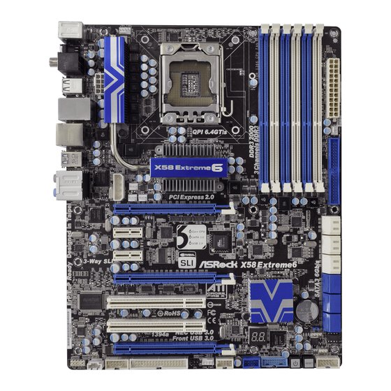
Page 12: Motherboard Layout
SATA3 Connector (SATA3_1_2, White) (HD_AUDIO1, White) SATA3 Connector (SATA3_3_4, White) HDMI_SPDIF Header (HDMI_SPDIF1, White) SATA3 Connector (SATA3_5_6, White) PCI Express 2.0 x16 Slot (PCIE5, Blue) SATAII Connector (SATAII_1_2, Blue) PCI Slots (PCI1-2) SATAII Connector (SATAII_3_4, Blue) PCI Express 2.0 x16 Slot (PCIE4, Blue) -
Page 13: I/O Panel
Clear CMOS Switch (CLRCBTN) ** 9 Front Speaker (Lime) PS/2 Keyboard Port (Purple) * There are two LED next to the LAN port. Please refer to the table below for the LAN port LED indications. LAN Port LED Indications ACT/LINK... - Page 14 To enable Multi-Streaming function, you need to connect a front panel audio cable to the front panel audio header. After restarting your computer, you will find “Mixer” tool on your system. Please select “Mixer ToolBox” , click “Enable playback multi-streaming”, and click “ok”.
-
Page 15: Installation
Chapter 2: Installation Chapter 2: Installation Chapter 2: Installation This is an ATX form factor (12.0" x 9.6", 30.5 x 24.4 cm) motherboard. Before you install the motherboard, study the configuration of your chassis to ensure that the motherboard fits into it. -
Page 16: Cpu Installation
Before you insert the 1366-Pin CPU into the socket, please check if the CPU surface is unclean or if there is any bent pin on the socket. Do not force to insert the CPU into the socket if above situation is found. - Page 17 1366-Pin CPU For proper inserting, please ensure to match the two orientation key notches of the CPU with the two alignment keys of the socket. Step 3-3. Carefully place the CPU into the socket by using a purely vertical motion.
-
Page 18: Installation Of Heatsink And Cpu Fan
This motherboard is equipped with 1366-Pin socket that supports Intel 1366-Pin CPU. Please adopt the type of heatsink and cooling fan compliant with Intel 1366-Pin CPU to dissipate heat. Before you installed the heatsink, you need to spray thermal interface material between the CPU and the heatsink to improve heat dissipation. -
Page 19: Installation Of Memory Modules (Dimm)
(the same brand, speed, size and chip-type) DDR3 DIMM pair in the slots of the same color. In other words, you have to install identi- cal DDR3 DIMM pair in Triple Channel (DDR3_A1, DDR3_B1 and DDR3_C1; White slots;... - Page 20 DIMMs or the system components. Step 1. Unlock a DIMM slot by pressing the retaining clips outward. Step 2. Align a DIMM on the slot such that the notch on the DIMM matches the break on the slot. notch break...
-
Page 21: Expansion Slots (Pci And Pci Express Slots)
2.6 Expansion Slots (PCI and PCI Express Slots) 2.6 Expansion Slots (PCI and PCI Express Slots) There are 2 PCI slots and 5 PCI Express slots on this motherboard. PCI slots: PCI slots are used to install expansion cards that have the 32-bit PCI interface. PCIE slots: PCIE2 / PCIE3 (PCIE x1 slot;... -
Page 22: Sli
(Even the GPU chips version shall be the same.) Insert one graphics card into PCIE1 slot and the other graphics card to PCIE4 slot. Make sure that the cards are properly seated on the slots. - Page 23 Make sure ASRock SLI_Bridge_2S Card is firmly in place. ASRock SLI_Bridge_2S Card Step4. Connect a VGA cable or a DVI cable to the monitor connector or the DVI connector of the graphics card that is inserted to PCIE1 slot.
- Page 24 3-Way SLI Bridge connector. Insert one graphics card into PCIE1 slot, another graphics card to PCIE4 slot, and the other graphics card to PCIE5 slot. Make sure that the cards are properly seated on the slots.
- Page 25 2.7.2 Driver Installation and Setup 2.7.2 Driver Installation and Setup 2.7.2 Driver Installation and Setup Install the graphics card drivers to your system. After that, you can enable the Multi- Graphics Processing Unit (GPU) feature in the NVIDIA nView system tray utility.
- Page 26 (For SLI and Quad SLI mode) A. Click the Start icon on your Windows taskbar. B. From the pop-up menu, select All Programs, and then click NVIDIA Corporation. C. Select NVIDIA Control Panel tab. D. Select Control Panel tab. E. From the pop-up menu, select Set SLI and PhysX configuration. In Set PhysX GPU acceleration item, please select Enabled.
- Page 27 D. You can freely enjoy the benefit of 3-Way SLI feature. * SLI appearing here is a registered trademark of NVIDIA Technologies Inc., and is used ® only for identification or explanation and to the owners’ benefit, without intent to infringe.
-
Page 28: Crossfirex Tm Tm
Cards Different CrossFireX cards may require different methods to enable CrossFireX feature. In below procedures, we use Radeon HD 3870 as the example graphics card. For other CrossFireX cards that ATI has released or will release in the future, please refer to ATI graphics card manuals for detailed installation guide. - Page 29 Step 3. Connect the DVI monitor cable to the DVI connector on the Radeon graphics card on PCIE1 slot. (You may use the DVI to D-Sub adapter to convert the DVI connector to D-Sub interface, and then connect the D-Sub monitor...
- Page 30 Cards Cards Cards Step 1. Install one Radeon graphics card to PCIE1 slot. For the proper installation procedures, please refer to section “Expansion Slots”. Step 2. Install one Radeon graphics card to PCIE4 slot. For the proper installation procedures, please refer to section “Expansion Slots”.
- Page 31 Step 5. Connect the DVI monitor cable to the DVI connector on the Radeon graphics card on PCIE1 slot. (You may use the DVI to D-Sub adapter to convert the DVI connector to D-Sub interface, and then connect the D-Sub monitor...
- Page 32 Install the CATALYST Control Center. Please check AMD website for details. Step 4. Restart your computer. Step 5. Install the VGA card drivers to your system, and restart your computer. Then you will find “ATI Catalyst Control Center” on your Windows taskbar. ®...
- Page 33 * CrossFireX appearing here is a registered trademark of ATI Technologies Inc., and is used only for identification or explanation and to the owners’ benefit, without intent to infringe. * For further information of ATI CrossFireX technology, please check AMD website for...
-
Page 34: Surround Display Feature
CLRCMOS1 for 5 seconds. However, please do not clear the CMOS right after you update the BIOS. If you need to clear the CMOS when you just finish updating the BIOS, you must boot up the system first, and then shut it down... -
Page 35: Onboard Headers And Connectors
(33-pin FLOPPY1) (see p.12 No. 30) FLOPPY1 Pin1 the red-striped side to Pin1 Note: Make sure the red-striped side of the cable is plugged into Pin1 side of the connector. Primary IDE connector (Blue) (39-pin IDE1, see p.12 No. 8) IDE1... - Page 36 Serial ATA (SATA) Either end of the SATA data cable Data Cable can be connected to the SATA / SATAII / SATA3 hard disk or the (Optional) SATAII / SATA3 connector on this motherboard. Serial ATA (SATA) Please connect the black end of...
-
Page 37: System Panel Header
Connect to the power status indicator on the chassis front panel. The LED is on when the system is operating. The LED keeps blinking when the sys-tem is in S1 sleep state. The LED is off when the system is in S3/S4 sleep state or powered off (S5). - Page 38 HDLED (Hard Drive Activity LED): Connect to the hard drive activity LED on the chassis front panel. The LED is on when the hard drive is reading or writing data. The front panel design may differ by chassis. A front panel module mainly consists of power switch, reset switch, power LED, hard drive activity LED, speaker and etc.
- Page 39 Though this motherboard provides 4-Pin CPU fan (Quiet Fan) support, the 3-Pin CPU fan still can work successfully even without the fan speed control function. If you plan to connect the 3-Pin CPU fan to the CPU fan connector on this motherboard, please connect it to Pin 1-3.
- Page 40 Intall the Front USB 3.0 Panel into the 3.5” drive bay. drive bay of the chassis. Step 3 Step 4 Plug the Front USB 3.0 cable into the USB 3.0 The Front USB 3.0 Panel is ready to use. header (USB3_1_2) on the motherboard.
-
Page 41: Smart Switches
CMOS values (see p.13 No. 17) You are not allowed to use Clear CMOS switch function if you set up the system password. If you want to clear the CMOS values, please clean your system password in advance or refer to page 34 “Clear CMOS jumper” description... -
Page 42: Dr. Debug
Please see the diagrams below for reading the Dr. Debug codes. The Bootblock initialization code sets up the chipset, memory and other components before system memory is available. The following table describes the type of checkpoints that may occur during the bootblock initialization portion of the BIOS: Checkpoint... - Page 43 Initializes the interrupt controlling hardware (generally PIC) and interrupt vector table. Do R/W test to CH-2 count reg. Initialize CH-0 as system timer. Install the POSTINT1Ch handler. Enable IRQ-0 in PIC for system timer interrupt. Traps INT1Ch vector to “POSTINT1ChHandlerBlock.”...
- Page 44 Initializes different devices through DIM. Initializes DMAC-1 & DMAC-2. Initialize RTC date/time. Test for total memory installed in the system. Also, Check for DEL or ESC keys to limit memory test. Display total memory in the system. Mid POST initialization of chipset registers.
-
Page 45: Installation
ICH10R south bridge chipset that supports Serial ATA ® (SATA) / Serial ATAII (SATAII) hard disks and RAID (RAID 0, RAID 1, RAID 10, RAID 5, and Intel Matrix Storage) functions. You may install SATA / SATAII hard disks on this motherboard for internal storage devices. -
Page 46: Hdds
SATA / SATAII HDD. What is Hot Swap Function? If SATA / SATAII HDDs are built as RAID1 or RAID 5 then it is called “Hot Swap” for the action to insert and remove the SATA / SATAII HDDs while the system is still power-on and in working condition. -
Page 47: Operation Guide
1. Below operation procedure is designed only for our motherboard, which supports SATA / SATAII / SATA3 HDD Hot Plug. * The SATA / SATAII / SATA3 Hot Plug feature might not be supported by the chipset because of its limitation, the SATA / SATAII / SATA3 Hot Plug support information of our motherboard is indicated in the product spec on our website: www.asrock.com... - Page 48 SATA / SATAII / SATA3 HDD damage and data loss. Step 1 Unplug SATA data cable from SATA / SATAII / SATA3 HDD side. Unplug SATA 15-pin power cable connector (Black) from SATA / SATAII / SATA3 HDD side. Step 2...
-
Page 49: Driver Installation Guide
2.19 Driver Installation Guide To install the drivers to your system, please insert the support CD to your optical drive first. Then, the drivers compatible to your system can be auto-detected and listed on the support CD driver page. Please follow the order from up to bottom side to install those required drivers. -
Page 50: Setting Up A "Raid Ready" System
SATA Hard Disks Installation and RAID Configuration”, which is located in the folder at the following path: .. \ RAID Installation Guide and the document in the support CD, “Guide to Intel Matrix Storage Manager”, which is located in the folder at the following path: .. \ Intel Matrix Storage Manager Information If you want to use “Intel Matrix Storage Manager”... -
Page 51: Migrating A "Raid Ready" System To Raid
Intel(R) Matrix Storage Console which can be used to manage the RAID configuration. 7. After setting up a “RAID Ready” system as the above steps, you can follow the procedures of the next section to migrate the system to RAID 0, RAID 1 or RAID 2.20.3... -
Page 52: Installing Windows ® 7 / 7 64-Bit / Vista
Support CD, “Guide to SATA Hard Disks Installation and RAID Configuration”, which is located in the folder at the following path: .. \ RAID Installation Guide and the document in the support CD, “Guide to Intel Matrix Storage Manager”, which is located in the folder at the following path: .. -
Page 53: Installing Windows ® 7 / 7 64-Bit / Vista
B. Set “SATAII Configuration” to [Enhanced], and then in the option “Configure SATAII as”, please set the option to [AHCI]. STEP 2: Make a SATA / SATAII driver diskette. Please make a SATA / SATAII driver diskette by following section 2.20.1 step 2 on page 49. ®... -
Page 54: Installing Windows ® 7 / 7 64-Bit / Vista
Untied Overclocking function, please enter “Overclock Mode” option of BIOS setup to set the selection from [Auto] to [Manual]. Therefore, CPU FSB is untied during overclocking, but PCI / PCIE buses are in the fixed mode so that FSB can operate under a more stable overclocking environment. -
Page 55: Bios Setup Utility
The BIOS FWH chip on the motherboard stores the BIOS SETUP UTILITY. You may run the BIOS SETUP UTILITY when you start up the computer. Please press <F2> or <Del> during the Power-On-Self-Test (POST) to enter the BIOS SETUP UTILITY, otherwise, POST will continue with its test routines. -
Page 56: Navigation Keys
3 . 2 3 . 2 Main Screen 3 . 2 Main Screen Main Screen When you enter the BIOS SETUP UTILITY, the Main screen will appear and display the system overview. BIOS SETUP UTILITY OC Tweaker Advanced H/W Monitor... -
Page 57: Oc Tweaker Screen
(C) Copyright 1985-2005, American Megatrends, Inc. Load CPU EZ OC Setting You can use this option to load CPU EZ overclocking setting. Please note that overclocing may cause damage to your CPU and motherboard. It should be done at your own risk and expense. - Page 58 Spread Spectrum This item should always be [Auto] for better system stability. CPU Ratio Setting If the ratio status is unlocked, you will find this item appear to allow you changing the ratio value of this motherboard. QPI Frequency Use this option to adjust QPI (QuickPath Interconnect) frequency. The default value is [Auto].
- Page 59 The default value is [Enabled]. Configuration options: [Enabled] and [Disabled]. If you want to enable this function, please set this item to [Enabled]. Besides the BIOS option, you can also choose our Intelligent Energy Saver utility to enable this function.
- Page 60 CPU PLL Voltage Use this to select CPU PLL Voltage. The default value is [Auto]. Would you like to save current setting user defaults? In this option, you are allowed to load and save three user defaults according to your own requirements.
-
Page 61: Advanced Screen
. Just launch ® this tool and save the new BIOS file to your USB flash drive, floppy disk or hard drive, then you can update your BIOS only in a few clicks without preparing an additional floppy diskette or other complicated flash utility. -
Page 62: Cpu Configuration
[Enabled] v02.54 (C) Copyright 1985-2005, American Megatrends, Inc. CPU Ratio Setting If the ratio status is unlocked, you will find this item appear to allow you changing the ratio value of this motherboard. Enhance Halt State (C1E) All processors support the Halt State (C1). The C1 state is supported through the native processor instructions HLT and MWAIT and requires no hardware support from the chipset. - Page 63 Intel (R) C-STATE tech. is achieved by making the power and thermal con- trol unit part of the core logic and not part of the chipset as before. Migration of the power and thermal management flow into the processor allows us...
-
Page 64: Chipset Configuration
Onboard 1394 This allows you to enable or disable the “Onboard 1394” feature. CIR10 Field 1 Use this to enable or disable CIR10 Field 1. The default value of this feature is [Enabled]. PCIE Max Payload Size This determines the maximum TLP (Transaction Layer Packet) payload size that can be supported by PCI Express controller. - Page 65 Good Night LED Enable this option to turn off Power LED, Lan LED and Port80 LED when the system is power on. The keyboard LED will also be turned off in S1, S3 and S4 state. The default value is [Disabled].
-
Page 66: Acpi Configuration
Use this item to enable or disable Ring-In signals to turn on the system from the power-soft-off mode. PCI Devices Power On Use this item to enable or disable PCI devices to turn on the system from the power-soft-off mode. PS/2 Keyboard Power On Use this item to enable or disable PS/2 keyboard to turn on the system from the power-soft-off mode. -
Page 67: Storage Configuration
“Configure SATAII as”, you are allowed to set the selection to [IDE], [RAID] or [AHCI]. The default value is [IDE]. If you select [RAID] or [AHCI] mode, the options “Hot Plug” and “SATA Link Power Management” will appear. - Page 68 [ARMD]: This is used for IDE ARMD (ATAPI Removable Media Device), such as MO. LBA/Large Mode Use this item to select the LBA/Large mode for a hard disk > 512 MB under DOS and Windows; for Netware and UNIX user, select [Disabled] to disable the LBA/Large mode.
-
Page 69: Pcipnp Configuration
AHCI CD/DVD Boot Time Out Some SATA CD / DVD in AHCI mode need to wait ready longer. Configuration options: [0], [5], [10], [15], [20], [25], [30] and [35]. The default value is [35]. 3 . 4 . 5 3 . 4 . 5... -
Page 70: Floppy Configuration
Use this item to enable or disable floppy drive controller. Serial Port Address Use this item to set the address for the onboard serial port or disable it. Configuration options: [Disabled], [3F8 / IRQ4], [2F8 / IRQ3], [3E8 / IRQ4], [2E8 / IRQ3]. -
Page 71: Usb Configuration
[Enabled] - Enables support for legacy USB. [Auto] - Enables legacy support if USB devices are connected. [Disabled] - USB devices are not allowed to use under legacy OS and BIOS setup when [Disabled] is selected. If you have USB compatibility issue, it is recommended to select [Disabled] to enter OS. -
Page 72: Hardware Health Event Monitoring Screen
3 . 5 Hardware Health Event Monitoring Screen In this section, it allows you to monitor the status of the hardware on your system, including the parameters of the CPU temperature, motherboard temperature, CPU fan speed, chassis fan speed, and the critical voltage. -
Page 73: Boot Screen
Boot Screen Boot Screen 3 . 6 3 . 6 Boot Screen In this section, it will display the available devices on your system for you to configure the boot settings and the boot priority. BIOS SETUP UTILITY Main OC Tweaker... -
Page 74: Security Screen
Security Screen 3 . 7 3 . 7 Security Screen In this section, you may set or change the supervisor/user password for the system. For the user password, you may also clear it. BIOS SETUP UTILITY Main OC Tweaker Advanced... -
Page 75: Exit Screen
When you select this option, it will pop-out the following message, “Discard changes?” Select [OK] to discard all changes. Load BIOS Defaults Load BIOS default values for all the setup questions. F9 key can be used for this operation. Load Performance Setup Default (IDE/SATA) This performance setup default may not be compatible with all system configurations. -
Page 76: Install Operating System
4 . 2 . 4 4 . 2 . 4 C o n t a c t I n f o r m a t i o n C o n t a c t I n f o r m a t i o n...
Need help?
Do you have a question about the X58 EXTREME6 - V1.0 and is the answer not in the manual?
Questions and answers