Table of Contents
Advertisement
Quick Links
Copyright Notice:
Copyright Notice:
Copyright Notice:
Copyright Notice:
Copyright Notice:
No part of this installation guide may be reproduced, transcribed, transmitted, or trans-
lated in any language, in any form or by any means, except duplication of documen-
tation by the purchaser for backup purpose, without written consent of ASRock Inc.
Products and corporate names appearing in this guide may or may not be registered
trademarks or copyrights of their respective companies, and are used only for identifica-
tion or explanation and to the owners' benefit, without intent to infringe.
Disclaimer:
Disclaimer:
Disclaimer:
Disclaimer:
Disclaimer:
Specifications and information contained in this guide are furnished for informational
use only and subject to change without notice, and should not be constructed as a
commitment by ASRock. ASRock assumes no responsibility for any errors or omissions
that may appear in this guide.
With respect to the contents of this guide, ASRock does not provide warranty of any kind,
either expressed or implied, including but not limited to the implied warranties or
conditions of merchantability or fitness for a particular purpose. In no event shall
ASRock, its directors, officers, employees, or agents be liable for any indirect, special,
incidental, or consequential damages (including damages for loss of profits, loss of
business, loss of data, interruption of business and the like), even if ASRock has been
advised of the possibility of such damages arising from any defect or error in the guide
or product.
This device complies with Part 15 of the FCC Rules. Operation is subject to the
following two conditions:
(1) this device may not cause harmful interference, and
(2) this device must accept any interference received, including interference that
may cause undesired operation.
CALIFORNIA, USA ONLY
The Lithium battery adopted on this motherboard contains Perchlorate, a toxic
substance controlled in Perchlorate Best Management Practices (BMP) regulations
passed by the California Legislature. When you discard the Lithium battery in
California, USA, please follow the related regulations in advance.
"Perchlorate Material-special handling may apply, see
www.dtsc.ca.gov/hazardouswaste/perchlorate"
ASRock Website: http://www.asrock.com
Copyright©2010 ASRock INC. All rights reserved.
ASRock X58 Extreme3 Motherboard
Published February 2010
1 1 1 1 1
Advertisement
Table of Contents

Related Manuals for ASROCK X58 EXTREME3


Summary of Contents for ASROCK X58 EXTREME3
- Page 1 ASRock. ASRock assumes no responsibility for any errors or omissions that may appear in this guide. With respect to the contents of this guide, ASRock does not provide warranty of any kind, either expressed or implied, including but not limited to the implied warranties or conditions of merchantability or fitness for a particular purpose.
-
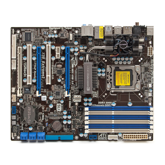
Page 2: Motherboard Layout
Chassis Intrusion Header (CI1) SATA3 Connector (SATA3_2, White) PCI Slot (PCI2) SATA3 Connector (SATA3_1, White) PCI Express 2.0 x16 Slot (PCIE3, Blue) Primary IDE Connector (IDE1, Blue) PCI Slot (PCI1) Clear CMOS Jumper (CLRCMOS1) PCI Express x1 Slot (PCIE2, White) SATAII Connector (SATAII_1_2, Blue) PCI Express 2.0 x16 Slot (PCIE1, Blue) - Page 3 Central / Bass (Orange) Clear CMOS Switch (CLRCBTN) Line In (Light Blue) PS/2 Keyboard Port (Purple) * There are two LED next to the LAN port. Please refer to the table below for the LAN port LED indications. LAN Port LED Indications ACT/LINK...
- Page 4 To enable Multi-Streaming function, you need to connect a front panel audio cable to the front panel audio header. After restarting your computer, you will find “VIA HD Audio Deck” tool on your system. Please follow below instructions according to the OS you install.
-
Page 5: Package Contents
This Quick Installation Guide contains introduction of the motherboard and step-by-step installation guide. More detailed information of the motherboard can be found in the user manual presented in the Support CD. Because the motherboard specifications and the BIOS software might be updated, the content of this manual will be subject to change without notice. -
Page 6: Specifications
Specifications Specifications Specifications Specifications Specifications Platform - ATX Form Factor: 12.0-in x 9.6-in, 30.5 cm x 24.4 cm - All Solid Capacitor design (100% Japan-made high-quality Conductive Polymer Capacitors) ® - Intel Socket 1366 Core i7 Processor Extreme Edition /... - Page 7 - 5 x Ready-to-Use USB 2.0 Ports - 1 x Powered eSATAIII/USB 2.0 Connector - 2 x Ready-to-Use USB 3.0 Ports - 1 x RJ-45 LAN Port with LED (ACT/LINK LED and SPEED LED) - 1 x IEEE 1394 Port - 1 x Clear CMOS Switch...
- Page 8 Overclocking may affect your system stability, or even cause damage to the components and devices of your system. It should be done at your own risk and expense. We are not responsible for possible damage caused by overclocking.
- Page 9 MS-DOS or Windows . With this utility, you can press <F6> key during the POST or press <F2> key to BIOS setup menu to access ASRock Instant Flash. Just launch this tool and save the new BIOS file to your USB flash drive, floppy disk or hard drive, then you can update your BIOS only in a few clicks without prepar- ing an additional floppy diskette or other complicated flash utility.
- Page 10 10. The software name itself – OC DNA literally tells you what it is capable of. OC DNA, an exclusive utility developed by ASRock, provides a conve- nient way for the user to record the OC settings and share with others. It helps you to save your overclocking record under the operating system and simplifies the complicated recording process of overclocking settings.
-
Page 11: Graphics Card Support List
LEADTEK PX9800 GTX+ GeForce 9800GTX+ 182.50 GIGABYTE GV-N26-896H-B GeForce GTX260 182.50 * For the latest updates of the supported PCI Express VGA card list for SLI Mode, please visit our website for details. ASRock website: http://www.asrock.com/support/index.htm ASRock X58 Extreme3 Motherboard... - Page 12 Powercolor AX3870X2 1GBD3-H RADEON 3870 Catalyst 9.1 Gecube GC-HD485PG3-E3 RADEON 4850 Catalyst 9.1 * For the latest updates of the supported PCI Express VGA card list for CrossFireX Mode, please visit our website for details. ASRock website: http://www.asrock.com/support/index.htm ASRock X58 Extreme3 Motherboard...
-
Page 13: Pre-Installation Precautions
Before you insert the 1366-Pin CPU into the socket, please check if the CPU surface is unclean or if there is any bent pin on the socket. Do not force to insert the CPU into the socket if above situation is found. - Page 14 100 degrees. Step 2. Remove PnP Cap (Pick and Place Cap). 1. It is recommended to use the cap tab to handle and avoid kicking off the PnP cap. 2. This cap must be placed if returning the motherboard for after service.
-
Page 15: Installation Of Cpu Fan And Heatsink
Installation of CPU Fan and Heatsink Installation of CPU Fan and Heatsink For proper installation, please kindly refer to the instruction manuals of your CPU fan and heatsink. Below is an example to illustrate the installation of the heatsink for 1366-Pin CPU. - Page 16 (the same brand, speed, size and chip-type) DDR3 DIMM pair in the slots of the same color. In other words, you have to install identi- cal DDR3 DIMM pair in Triple Channel (DDR3_A1, DDR3_B1 and DDR3_C1; White slots;...
-
Page 17: Installing A Dimm
Unlock a DIMM slot by pressing the retaining clips outward. Step 2. Align a DIMM on the slot such that the notch on the DIMM matches the break on the slot. The DIMM only fits in one correct orientation. It will cause permanent damage to the motherboard and the DIMM if you force the DIMM into the slot at incorrect orientation. -
Page 18: Expansion Slots (Pci And Pci Express Slots)
2.4 Expansion Slots (PCI and PCI Express Slots) 2.4 Expansion Slots (PCI and PCI Express Slots) There are 2 PCI slots and 4 PCI Express slots on this motherboard. PCI slots: PCI slots are used to install expansion cards that have the 32-bit PCI interface. PCIE slots: PCIE2 (PCIE x1 slot;... -
Page 19: Sli Tm And Quad Sli
(Even the GPU chips version shall be the same.) Insert one graphics card into PCIE1 slot and the other graphics card to PCIE3 slot. Make sure that the cards are properly seated on the slots. -
Page 20: Driver Installation And Setup
Make sure ASRock SLI_Bridge_2S Card is firmly in place. ASRock SLI_Bridge_2S Card Step4. Connect a VGA cable or a DVI cable to the monitor connector or the DVI connector of the graphics card that is inserted to PCIE1 slot. 2.5.2 Driver Installation and Setup 2.5.2 Driver Installation and Setup... - Page 21 C. Select NVIDIA Control Panel tab. D. Select Control Panel tab. E. From the pop-up menu, select Set SLI and PhysX configuration. In Set PhysX GPU acceleration item, please select Enabled. In Select an SLI configuration item, please select Enable SLI. And click Apply.
-
Page 22: Operation
Cards Different CrossFireX cards may require different methods to enable CrossFireX feature. In below procedures, we use Radeon HD 3870 as the example graphics card. For other CrossFireX cards that ATI has released or will release in the future, please refer to ATI graphics card manuals for detailed installation guide. - Page 23 Step 3. Connect the DVI monitor cable to the DVI connector on the Radeon graphics card on PCIE1 slot. (You may use the DVI to D-Sub adapter to convert the DVI connector to D-Sub interface, and then connect the D-Sub monitor cable to the DVI to D-Sub adapter.)
- Page 24 Install the CATALYST Control Center. Please check AMD website for details. Step 4. Restart your computer. Step 5. Install the VGA card drivers to your system, and restart your computer. Then you will find “ATI Catalyst Control Center” on your Windows ® taskbar.
- Page 25 * CrossFireX appearing here is a registered trademark of ATI Technologies Inc., and is used only for identification or explanation and to the owners’ benefit, without intent to infringe. * For further information of ATI CrossFireX technology, please check AMD website for updates and details.
-
Page 26: Surround Display Feature
After waiting for 15 seconds, use a jumper cap to short pin2 and pin3 on CLRCMOS1 for 5 seconds. However, please do not clear the CMOS right after you update the BIOS. -
Page 27: Onboard Headers And Connectors
FDD connector (33-pin FLOPPY1) (see p.2 No. 31) the red-striped side to Pin1 Note: Make sure the red-striped side of the cable is plugged into Pin1 side of the connector. Primary IDE connector (Blue) (39-pin IDE1, see p.2 No. 14) - Page 28 Serial ATA (SATA) Either end of the SATA data cable Data Cable can be connected to the SATA / SATAII hard disk or the SATAII (Optional) connector on this motherboard. Serial ATA (SATA) Please connect the black end of Power Cable SATA power cable to the power connector on each drive.
- Page 29 HDA to function correctly. Please follow the instruction in our manual and chassis manual to install your system. 2. If you use AC’97 audio panel, please install it to the front panel audio header as below: A.
- Page 30 Though this motherboard provides 4-Pin CPU fan (Quiet Fan) support, the 3-Pin CPU fan still can work successfully even without the fan speed control function. If you plan to connect the 3-Pin CPU fan to the CPU fan connector on this motherboard, please connect it to Pin 1-3.
- Page 31 Though this motherboard provides 8-pin ATX 12V power connector, it can still work if you adopt a traditional 4-pin ATX 12V power supply. To use the 4-pin ATX power supply, please plug your power supply along with Pin 1 and Pin 5.
-
Page 32: Smart Switches
CMOS values (see p.2 No. 17) You are not allowed to use Clear CMOS switch function if you set up the system password. If you want to clear the CMOS values, please clean your system password in advance or refer to page 26 “Clear CMOS jumper” description instead. - Page 33 Please see the diagrams below for reading the Dr. Debug codes. The Bootblock initialization code sets up the chipset, memory and other components before system memory is available. The following table describes the type of checkpoints that may occur during the bootblock initialization portion of the BIOS: Checkpoint...
-
Page 34: Post Code Checkpoints
Initializes the interrupt controlling hardware (generally PIC) and interrupt vector table. Do R/W test to CH-2 count reg. Initialize CH-0 as system timer. Install the POSTINT1Ch handler. Enable IRQ-0 in PIC for system timer interrupt. Traps INT1Ch vector to “POSTINT1ChHandlerBlock.”... - Page 35 Initializes different devices through DIM. Initializes DMAC-1 & DMAC-2. Initialize RTC date/time. Test for total memory installed in the system. Also, Check for DEL or ESC keys to limit memory test. Display total memory in the system. Mid POST initialization of chipset registers.
-
Page 36: Installing Windows Functions
2.12 Driver Installation Guide To install the drivers to your system, please insert the support CD to your optical drive first. Then, the drivers compatible to your system can be auto-detected and listed on the support CD driver page. Please follow the order from up to bottom side to install those required drivers. -
Page 37: Untied Overclocking Technology
Untied Overclocking function, please enter “Overclock Mode” option of BIOS setup to set the selection from [Auto] to [Manual]. Therefore, CPU FSB is untied during overclocking, but PCI / PCIE buses are in the fixed mode so that FSB can operate under a more stable overclocking environment. -
Page 38: Bios Information
ROM drive. It will display the Main Menu automatically if “AUTORUN” is enabled in your computer. If the Main Menu does not appear automatically, locate and double- click on the file “ASSETUP.EXE” from the BIN folder in the Support CD to display the menus. - Page 39 ASRock gefertigt wurde. Es bietet Ihnen exzellente Leistung und robustes Design, gemäß der Verpflichtung von ASRock zu Qualität und Halbarkeit. Diese Schnellinstallationsanleitung führt in das Motherboard und die schrittweise Installa- tion ein. Details über das Motherboard finden Sie in der Bedienungsanleitung auf der Support-CD. Da sich Motherboard-Spezifikationen und BIOS-Software verändern können, kann der Inhalt dieses Handbuches ebenfalls jederzeit geändert...
-
Page 40: Spezifikationen
Spezifikationen Spezifikationen Spezifikationen Spezifikationen Spezifikationen Plattform - ATX-Formfaktor: 30.5 cm x 24.4 cm; 12.0 Zoll x 9.6 Zoll - Alle Feste Kondensatordesign (100% in Japan gefertigte, erstklassige leitfähige Polymer-Kondensatoren) ® - Intel -Sockel 1366 Core i7-Prozessor Extreme Edition / Core i7-Prozessor unterstützt Intel... - Page 41 - 5 x Standard-USB 2.0-Anschlüsse - 1 x eSATAIII/USB 2.0-Anschluss mit Stromversorgung - 2 x Standard-USB 3.0-Anschlüsse - 1 x RJ-45 LAN Port mit LED (ACT/LINK LED und SPEED LED) - 1 x IEEE 1394 Port - 1 x CMOS löschen-Schalter...
- Page 42 - 1 x Netzschalter mit LED - 1 x Rücksetzschalter (Reset) mit LED BIOS - 8Mb AMI BIOS - AMI legal BIOS mit Unterstützung für “Plug and Play” - ACPI 1.1-Weckfunktionen - JumperFree-Übertaktungstechnologie - SMBIOS 2.3.1 - Zentraleinheit, VCCM, IOH, ICH, VTT, IOH/ICH PCIE, CPU PLL, IOH CSI, VCORE Stromspannung Multianpassung - Unterstützt I.
- Page 43 Beachten Sie bitte, dass Overclocking, einschließlich der Einstellung im BIOS, Anwenden der Untied Overclocking-Technologie oder Verwenden von Overclocking-Werkzeugen von Dritten, mit einem gewissen Risiko behaftet ist. Overclocking kann sich nachteilig auf die Stabilität Ihres Systems auswirken oder sogar Komponenten und Geräte Ihres Systems beschädigen.
- Page 44 USB-Flash-Laufwerk oder die Festplatte das Dateisystem FAT32/16/12 benutzen muss. 10. Allein der Name – OC DNA* – beschreibt es wörtlich, was die Software zu leisten vermag. OC DNA ist ein von ASRock exklusiv entwickeltes Dienstprogramm, das Nutzern eine bequeme Möglichkeit bietet, Übertaktungseinstellungen aufzuzeichnen und sie Anderen mitzuteilen.
-
Page 45: Cpu Installation
Sicherheitshinweise vor der Montage Sicherheitshinweise vor der Montage Sicherheitshinweise vor der Montage Bitte nehmen Sie die folgende Sicherheitshinweise zur Kenntnis, bevor Sie das Motherboard einbauen oder Veränderungen an den Einstellungen vornehmen. Trennen Sie das System vom Stromnetz, bevor Sie eine ystemkomponente berühren, da es sonst zu schweren Schäden am Motherboard oder den... - Page 46 Schritt 2. PnP-Kappe entfernen (Pick and Place-Kappe). 1. Verwenden Sie beim Entfernen die Kappenlasche und vermeiden Sie ein Abreißen der PnP-Kappe. 2. Diese Kappe muss angebracht werden, falls Sie das Motherboard zur Reparatur bringen. Schritt 3. 1366-Pin CPU einstecken: Schritt 3-1. Halten Sie die CPU an den mit schwarzen Linien gekennzeichneten Seiten.
- Page 47 Um die CPU ordnungsgemäß einsetzen zu können, richten Sie die zwei Orientierungskerben der CPU mit den beiden Markierungen des Sockels aus. Schritt 3-3. Drücken Sie die CPU vorsichtig in vertikaler Richtung in den Sockel. Schritt 3-4. Prüfen Sie, dass die CPU ordnungsgemäß...
- Page 48 Installation des CPU-Lüfters und Kühlkörpers Für Installationshinweise, siehe Betriebsanleitung Ihres CPU-Lüfters und Kühlkörpers. Unten stehend ein Beispiel zur Installation eines Kühlkörpers für den 1366-Pin CPU. (Tragen Sie Wärmeleitmaterial auf. ) Schritt 1. Geben Sie Wärmeleitmaterial auf die Mitte des IHS, auf die Sockeloberfläche.
- Page 49 Triple-Kanal (DDR3_A1, DDR3_B1 und DDR3_C1; Weiß Steckplätze, siehe Seite 2 Nr. 7) oder ein identisches DDR3 DIMM-Paar im Triple-Kanal (DDR3_A2, DDR3_B2 und DDR3_C2; Blau Steckplätze, siehe Seite 2 Nr. 11) installieren, damit die Triple- Kanal-Speichertechnologie aktiviert werden kann. Auf diesem Motherboard können Sie auch sechs DDR3 DIMMs für eine Triple-Kanalkonfiguration installieren.
- Page 50 Öffnen Sie einen DIMM-Slot, indem Sie die seitlichen Clips nach außen drücken. Schritt 2: Richten Sie das DIMM-Modul so über dem Slot aus, dass das Modul mit der Kerbe in den Slot passt. Die DIMM-Module passen nur richtig herum eingelegt in die Steckplätze.
- Page 51 Gehäuseschacht (Slot) , den Sie nutzen möchten und behalten die Schraube für den Einbau der Karte. Schritt 3: Richten Sie die Karte über dem Slot aus und drücken Sie sie ohne Gewalt hinein, bis sie den Steckplatz korrekt ausfüllt. Schritt 4: Befestigen Sie die Karte mit der Schraube aus Schritt 2.
- Page 52 -Bedienungsanleitung ® Dieses Motherboard unterstützt NVIDIA - und Quad SLI - (Scalable Link Interface) Technologie, die Ihnen die Installation von bis zu zwei identischen PCI Express x16-Grafikkarten gestattet. Derzeit unterstützt die NVIDIA ® ® Technologie die Betriebssysteme Windows 7 / 7 64-Bit / Vista...
-
Page 53: Einstellung Der Jumper
+5VSB (Standby) zu setzen (siehe S.2 - No. 1) und die PS/2 oder USB- Weckfunktionen zu aktivieren. Hinweis: Um +5VSB nutzen zu können, muss das Netzteil auf dieser Leitung 2A oder mehr leisten können. CMOS löschen (CLRCMOS1, 3-Pin jumper) (siehe S.2 - Nr. 15) - Page 54 (33-Pin FLOPPY1) die rotgestreifte Seite auf Stift 1 (siehe S.2 - No. 31) Hinweis: Achten Sie darauf, dass die rotgestreifte Seite des Kabel mit der Stift 1- Seite des Anschlusses verbunden wird. Primärer IDE-Anschluss (blau) (39-pin IDE1, siehe S.2 - No. 14)
- Page 55 Seriell-ATA3-Anschlüsse Diese zwei Serial ATA3- (SATA3-)Verbínder (SATA3_1: siehe S.2 - No. 13) unterstützten SATA-Datenkabel (SATA3_2: siehe S.2 - No. 12) für interne Massenspeichergeräte. Die aktuelle SATA3- Schnittstelle ermöglicht eine Datenübertragungsrate bis 6,0 Gb/s. Serial ATA- (SATA-) SJedes Ende des SATA...
- Page 56 TPM-Stiftleiste Dieser Anschluss unterstützt ein Trusted Platform Module-System (19-Pin TPM1) (TPM: Vertrauenswürdiges (siehe S.2 - No. 29) Plattformmodul), auf dem sich Schlüssel, Digitalzertifikate, Kennwörter und Daten auf sichere Weise speichern lassen. Ein TPM-System hilft auch bei der Verbesserung der Netzwerksicherheit, schützt digitale Identitäten und sorgt für...
- Page 57 Geräte), wobei jedoch die Bildschirmverdrahtung am Gehäuse HDA unterstützen muss, um richtig zu funktionieren. Beachten Sie bei der Installation im System die Anweisungen in unserem Handbuch und im Gehäusehandbuch. 2. Wenn Sie die AC’97-Audioleiste verwenden, installieren Sie diese wie nachstehend beschrieben an der Front-Audioanschlussleiste: A.
- Page 58 Obwohl dieses Motherboard einen 24-pol. ATX-Stromanschluss bietet, kann es auch mit einem modifizierten traditionellen 20-pol. ATX-Netzteil verwendet werden. Um ein 20-pol. ATX-Netzteil zu verwenden, stecken Sie den Stecker mit Pin 1 und Pin 13 ein. Installation eines 20-pol. ATX-Netzteils ASRock X58 Extreme3 Motherboard...
- Page 59 Obwohl diese Hauptplatine 8-Pin ATX 12V Stromanschluss zur Verfügung stellt, kann sie noch arbeiten, wenn Sie einen traditionellen 4-Pin ATX 12V Energieversorgung adoptieren. Um die 4-Pin ATX Energieversorgung zu verwenden, stecken Sie bitte Ihre Energieversorgung zusammen mit dem Pin 1 und Pin 5 ein.
- Page 60 HDMI_SPDIF-Kabels mit dem HDMI_SPDIF-Anschluss am Motherboard. Schließen Sie dann das weiße Ende (B oder C) des HDMI_SPDIF-Kabels an den HDMI_SPDIF-Anschluss der HDMI-VGA-Karte an. A. Schwarzes Ende B. Weißes Ende (zweipolig) C. Weißes Ende (dreipolig) 2.10 2.10 Schnellschalter Schnellschalter 2.10 2.10 2.10 Schnellschalter...
-
Page 61: 64-Bit / Vista
Anschließend werden die mit Ihrem System kompatiblen Treiber automatisch erkannt und auf dem Bildschirm angezeigt. Zur Installation der nötigen Treiber gehen Sie bitte der Reihe nach von oben nach unten vor. Nur so können die von Ihnen installierten Treiber richtig arbeiten. - Page 62 7 / 7 64-Bit / Vista / Vista 64-Bit ohne RAID-Funktionalität auf Ihren SATA / SATAII-Festplatten installieren, gehen Sie bitte wie folgt vor. Verwendung von SATA / SATAII-Festplatten ohne NCQ-Funktionen SCHRITT 1: BIOS einrichten. A. Rufen Sie das BIOS SETUP UTILITY auf, wählen Sie den „Advanced“- Bildschirm (Erweitert), dann „Storage Configuration“...
- Page 63 Erscheint der Wilkommensbildschirm nicht, so “doppelklicken” Sie bitte auf das File ASSETUP.EXE im BIN-Verzeichnis der Support-CD, um die Menüs aufzurufen. Das Setup-Programm soll es Ihnen so leicht wie möglich machen. Es ist menügesteuert, d.h. Sie können in den verschiedenen Untermenüs Ihre Auswahl treffen und die Programme werden dann automatisch installiert.
-
Page 64: Contenu Du Paquet
1. Introduction 1. Introduction Merci pour votre achat d’une carte mère ASRock X58 Extreme3, une carte mère très fiable produite selon les critères de qualité rigoureux de ASRock. Elle offre des performances excellentes et une conception robuste conformément à l’engagement d’ASRock sur la qualité... -
Page 65: Spécifications
- Prend en charge le profil de mémoire extrême Intel ® (XMP) Slot d’extension - 2 x slot PCI Express 2.0 x16 (bleu @ x16 modes) - 1 x slot PCI Express x16 (blanc@ x4 mode) (espacement faisant deux fois la taille d’une fente entre chaque fente PCI-E) - Page 66 - 2 x connecteurs SATA3 6,0 Gb/s par Marvell SE9128, prennent en charge les fonctions RAID matériel (RAID 0 et RAID 1), NCQ, AHCI et « Hot Plug » (Branchement à chaud) (le connecteur SATA3_2 est partagé avec le port eSATA3) USB 3.0...
- Page 67 - br. 8 connecteur d’alimentation 12V ATX - Connecteurs audio internes - Connecteur audio panneau avant - 2 x En-tête USB 2.0 (prendre en charge 4 ports USB 2.0 supplémentaires) (voir ATTENTION 6) Interrupteur - 1 x interrupteur d’effacement du CMOS avec LED rapide - 1 x interrupteur d’alimentation avec LED...
- Page 68 * Pour de plus amples informations sur les produits, s’il vous plaît visitez notre site web: http://www.asrock.com ATTENTION Il est important que vous réalisiez qu’il y a un certain risque à effectuer l’overclocking, y compris ajuster les réglages du BIOS, appliquer la technologie Untied Overclocking, ou utiliser des outils de tiers pour l’overclocking.
- Page 69 Pour améliorer la dissipation de la chaleur, n’oubliez pas de mettre de la pâte thermique entre le CPU le dissipateur lors de l’installation du PC.
- Page 70 A chaque désinstallation de composant, placez-le sur un support antistatique ou dans son sachet d’origine. Lorsque vous placez les vis dans les orifices pour vis pour fixer la carte mère sur le châssis, ne serrez pas trop les vis ! Vous risquez sinon d’endommager la carte mère.
- Page 71 1. Il est recommandé d’utiliser la languette du capuchon ; évitez de faire sortir le capuchon PnP. 2. Ce capuchon doit être mis en place si vous renvoyez la carte mère pour service après vente. Etape 3. Insérez le processeur 1366 broches : Etape 3-1.
- Page 72 Pour une insertion correcte, veuillez vérifier que vous faites bien correspondre les deux encoches d’orientation sur le processeur avec les deux détrompeurs du socket Etape 3-3. Mettez soigneusement en place le processeur dans le socle en un mouvement strictement vertical.
- Page 73 Répétez l’opération avec les autres attaches. (Enfoncez (4 endroits)) Si vous enfoncez les attaches sans les faire tourner dans le sens des aiguilles d’une montre, le dissipateur thermique ne sera pas fixé sur la carte mère.
- Page 74 DIMM DDR3 identiques (de la même marque, de la même vitesse, de la même taille et du même type de puce) dans les slots de même couleur. En d’autres termes, vous devez installer une paire de DIMM DDR3 identiques dans le Canal Triple (DDR3_A1, DDR3_B1 et DDR3_C1;...
- Page 75 Installation d’un module DIMM Installation d’un module DIMM Installation d’un module DIMM Ayez bien le soin de débrancher l’alimentation avant d’ajouter ou de retirer des modules DIMM ou les composants du système. Etape 1. Déverrouillez un connecteur DIMM en poussant les taquets de maintien vers l’extérieur.
-
Page 76: Installation D'une Carte D'extension
Slot d’extension (Slots PCI et Slots PCI Express) Slot d’extension (Slots PCI et Slots PCI Express) Il y a 2 ports PCI et 4 ports PCI Express sur la carte mère X58 Extreme3. Slots PCI: Les slots PCI sont utilisés pour installer des cartes d’extension dotées d’une interface PCI 32 bits. - Page 77 2.7 “Surround Display” 2.7 “Surround Display” Cette carte mère supporte la mise à niveau de Surround Display. Avec la carte externe d’extension VGA PCI Express, vous pouvez facilement jouir des avantages de la caractéristique de l’affichage Surround. Pour les instructions détaillées, veuillez vous reporter au document qui se trouve sur le chemin suivant...
- Page 78 Toutefois, veuillez ne pas effacer la CMOS tout de suite après avoir mis le BIOS à jour. Si vous avez besoin d’effacer la CMOS lorsque vous avez fini de mettre le BIOS à jour, vous devez d’abord initialiser le système, puis le mettre hors tension avant de procéder à...
- Page 79 (voir p.2 No. 31) le côté avec fil rouge côté Broche1 Note: Assurez-vous que le côté avec fil rouge du câble est bien branché sur le côté Broche1 du connecteur. Connecteur IDE primaire (bleu) (IDE1 br. 39, voir p.2 No. 14)
- Page 80 6,0 Gb/s. Câble de données Toute cote du cable de data SATA Série ATA (SATA) peut etre connecte au disque dur SATA / SATAII / SATA3 ou au (en option) connecteur SATAII / SATA3 sur la carte mere.
- Page 81 1. L’audio à haute définition (HDA) prend en charge la détection de fiche, mais le fil de panneau sur le châssis doit prendre en charge le HDA pour fonctionner correctement. Veuillez suivre les instructions dans notre manuel et le manuel de châssis afin installer votre système.
- Page 82 E. Entrer dans l’utilitaire de configuration du BIOS. Saisir les Paramètres avancés puis sélectionner Configuration du jeu de puces. Définir l’option panneau de commande de [Auto] à [Activé]. En-tête du panneau système Cet en-tête permet d’utiliser plusieurs fonctions du (PANEL1 br.9) panneau système frontal.
- Page 83 (voir p.2 No. 2) ien que cette carte mère offre un support de (Ventilateur silencieux) ventilateur de CPU à 4 broches , le ventilateur de CPU à 3 broches peut bien fonctionner même sans la fonction de commande de vitesse du ventilateur.
- Page 84 En-tête de port COM Cette en-tête de port COM est utilisée pour prendre en charge (COM1 br.9) un module de port COM. (voir p.2 No. 30) Connecteur HDMI_SPDIF Connecteur HDMI_SPDIF, fournissant une sortie audio (HDMI_SPDIF1 3-pin) SPDIF vers la carte VGA HDMI, (voir p.2 No.
- Page 85 (Effacement du CMOS) si vous configurez un mot de passe pour le système. Si vous voulez effacer les valeurs du CMOS, veuillez d’abord effacer le mot de passe de votre système ou vous référer plutôt à la description “Clear CMOS jumper (Cavalier d’effacement du CMOS)” de la page 78.
-
Page 86: 64-Bit / Vista
2.11 LED de débogage La LED de débogage intégrée sert à fournir des informations de code, ce qui rend le dépannage encore plus facile. Veuillez consulter les diagrammes des pages 33, 34 et 35 pour la lecture des codes LED de débogage. - Page 87 7 / 7 64-bit / Vista / Vista 64-bit sur vos disques durs SATA / SATAII sans les fonctions RAID, veuillez suivre la procédure ci-dessous. Utilisation des disques durs SATA / SATAII sans NCQ fonctions ETAPE 1 : Configurez le BIOS.
-
Page 88: Informations Sur Le Cd De Support
BIOS après le POST, veuillez redémarrer le système en pressant <Ctl> + <Alt> + <Suppr>, ou en pressant le bouton de reset sur le boîtier du système. Vous pouvez également redémarrer en éteignant le système et en le rallumant. -
Page 89: Contenuto Della Confezione
Grazie per aver scelto una scheda madre ASRock X58 Extreme3, una scheda madre affidabile prodotta secondo i severi criteri di qualità ASRock. Le prestazioni eccellenti e il design robusto si conformano all’impegno di ASRock nella ricerca della qualità e della resistenza. - Page 90 1.2 Specifiche Specifiche Specifiche Specifiche Specifiche Piattaforma - ATX Form Factor: 12.0-in x 9.6-in, 30.5 cm x 24.4 cm - Design condensatore compatto (condensatori a conduttore in polimero di alta qualità realizzati al 100% in Giappone) ® Processore - Processore Intel...
- Page 91 (vedi ATTENZIONE 5) SATA3 - 2 x Connettori SATA3 6,0Gb/s SE9128 Marvell, supporto RAID hardware (RAID 0 e RAID 1) e delle funzioni NCQ, AHCI e “Hot Plug” (il connettore SATA3_2 è condiviso con la porta eSATA3) USB 3.0 - 2 x Porte USB3.0 UPD720200 NEC, supporto di USB 1.0/2.0/3.0...
- Page 92 * Per ulteriori informazioni, prego visitare il nostro sito internet: http://www.asrock.com AVVISO Si prega di prendere atto che la procedura di overclocking implica dei rischi, come anche la regolazione delle impostazioni del BIOS, l’applicazione della tecnologia Untied Overclocking Technology, oppure l’uso di strumenti di overclocking forniti da terzi. L’overclocking può...
- Page 93 (dischi floppy) o altre complicate utilità Flash. Si prega di notare che l’unità Flash USB o il disco rigido devono usare il File System FAT32/16/ 10. Il nome stesso del software – OC DNA – dice di cosa è capace. OC DNA, una utilità esclusiva sviluppata da ASRock, fornisce un modo comodo per registrare le impostazioni OC e condividerle con gli altri.
-
Page 94: Installazione
Intel l’alimentatore predisposto EuP deve soddisfare lo standard secondo cui l’efficienza energetica in standby di 5 v è più alta del 50% con un consumo di corrente di 100 mA. Per la scelta di un’alimentatore predisposto EuP consigliamo di verificare ulteriori dettagli con il produttore. - Page 95 Vista del socket 1366-Pin Prima da inserire la CPU da 1366-Pin nel socket, verificare che la superficie della CPU sia pulita e che non ci siano pin piegati nel socket. Non forzare l’inserimento della CPU nel socket se ci sono pin piegati. In caso contrario la CPU potrebbe essere seriamente danneggiata.
- Page 96 Socket da 1366-Pin Dente di orientamento CPU da 1366-Pin Per il corretto inserimento, verificare di far combaciare i due denti di allineamento della CPU con le due tacche nel socket. Fase 3-3. Collocare con delicatezza la CPU sulla presa con un movimento puramente verticale.
- Page 97 (Premere verso il basso (4 punti)) Se si premono i fastener verso il basso, senza ruotarli in senso orario, il dissipatore non viene fissato bene alla scheda madre Fase 5. Collegare il cavo di alimentazione della ventola al connettore ventola della CPU sulla scheda madre.
- Page 98 2.3 Installazione dei moduli di memoria (DIMM) 2.3 Installazione dei moduli di memoria (DIMM) Questa scheda madre fornisce sei alloggi DIMM DDR3 (Double Data Rate 3) a 240 pin, e supporta la tecnologia Triple Channel Memory. Per la configurazione a tre canali, è...
- Page 99 Sbloccare lo slot DIMM premendo i fermi che lo trattengono verso l’esterno. Step 2. Allineare una DIMM sullo slot così che il pettine della DIMM combaci con la sua sede sullo slot. La DIMM può essere montata correttamente soltanto con un orientamento.
- Page 100 Step 2. Rimuovere i ganci sullo slot che si intende utilizzare. Tenere a portata di mano le viti. Step 3. Allineare il connettore della scheda con lo slot e premere con decisione finché...
- Page 101 Quad SLI ® Questa scheda madre supporta a tecnologia NVIDIA e Quad SLI (Scalable Link Interface) che permette di installare fino a due schede video PCI Express x16 identiche. Correntemente, la tecnologia NVIDIA ® supporta i sistemi operativi ®...
- Page 102 Azzeramento predefinita CMOS Nota: CLRCMOS1 permette di cancellare i dati presenti nel CMOS. I dati del CMOS comprendono le informazioni di configurazione quali la password di sistema, data, ora, e i parametri di configurazione del sistema. Per cancellare e ripristinare i parametri del sistema, spegnere il computer e togliere il cavo di alimentazione dalla presa di corrente.
- Page 103 (33-pin FLOPPY1) Lato del Pin1 con la striscia (vedi p.2 Nr. 31) rossa Nota: Assicurarsi che il lato del cavo con la striscia rossa sia inserito nel lato Pin1 del connettore. Connettore IDE primario (blu) (39-pin IDE1, vedi p.2 Nr. 14)
- Page 104 6.0 Gb/s. Cavi dati Serial ATA (SATA) Una o altra estremità del cavo di dati SATA può essere (Opzionale) collegata al disco rigido SATA / SATAII / SATA3 o al connettore di SATAII / SATA3 su questa cartolina base.
- Page 105 1. La caratteristica HDA (High Definition Audio) supporta il rilevamento dei connettori, però il pannello dei cavi sul telaio deve supportare la funzione HDA (High Definition Audio) per far sì che questa operi in modo corretto. ore supporta un Attenersi alle istruzioni del nostro manuale e del manuale del telaio per Platform Module installare il sistema.
- Page 106 Sebbene la presente scheda madre disponga di un supporto per ventola CPU a 4 piedini (ventola silenziosa), la ventola CPU a 3 piedini è in grado di funzionare anche senza la funzione di controllo della velocità della ventola. Se si intende collegare la ventola CPU a 3 piedini al connettore della ventola CPU su questa scheda madre, collegarla ai piedini 1-3.
- Page 107 ATX a 24 pin, ma può funzionare lo stesso se si adotta un alimentatore ATX a 20 pin. Per usare l’alimentatore ATX a 20 pin, collegare l’alimentatore con il Pin 1 e il Pin 13. Installazione dell’alimentatore ATX a 20 pin...
- Page 108 Interruttori rapidi Interruttori rapidi Questa scheda madre ha tre interruttori rapidi: Interruttore di alimentazione, interruttore di reset e interruttore pulizia CMOS, che consentono agli utenti di accendere / spegnere rapidamente o cancellare i valori CMOS. Interruttore L’interruttore di alimentazione è...
- Page 109 Quindi, i driver compatibili con il sistema vengono rilevati automaticamente ed elencati nella pagina del driver del CD in dotazione. Per l’installazione dei driver necessari, procedere in base ad un ordine dall’alto verso il basso. In tal modo, i driver installati funzioneranno correttamente.
- Page 110 7 / 7 64-bit / Vista / Vista 64-bit sulle unità disco rigido SATA / SATAII senza funzioni RAID, seguire le istruzioni esposte di seguito. Utilizzo dei dischi rigidi SATA / SATAII privi di funzioni NCQ Passo 1: Configurare il BIOS.
- Page 111 BIOS; altrimenti, POST continua con i suoi test di routine. Per entrare il BIOS Setup dopo il POST, riavvia il sistema premendo <Ctl> + <Alt> + <Delete>, o premi il tasto di reset sullo chassis del sistema. Per informazioni più dettagliate circa il Setup del BIOS, fare riferimento al Manuale dell’Utente (PDF file) contenuto nel cd di...
-
Page 112: Contenido De La Caja
ASRock. Esta Guía rápida de instalación contiene una introducción a la placa base y una guía de instalación paso a paso. Puede encontrar una información más detallada sobre la placa base en el manual de usuario incluido en el CD de soporte. - Page 113 1.2 Especificación Especificación Especificación Especificación Especificación Plataforma - Factor forma ATX: 30,5 cm x 24,4 cm, 12,0” x 9,6” - Todo diseño de Capacitor Sólido (condensadores de polímero conductor de alta calidad 100% fabricados en Japón) Procesador - Procesador Intel ®...
- Page 114 Central/Bajos / Entrada de línea / Altavoz frontal / Micrófono (ver ATENCIÓN 5) SATA3 - 2 x conectores SATA 3 de 6,0 Gb/s con chip Marvell SE9128 compatibles con funciones RAID (RAID 0 y RAID 1), NCQ, AHCI y de “Hot Plug” (conexión en caliente) por hardware (los puertos SATA3_2 y eSATA3 son compartidos) USB 3.0...
- Page 115 - Taquímetros de los ventiladores del procesador y del CPU / chasis / NB / alimentación - Ventilador silencioso para procesador - Control de ajuste de la velocidad del ventilador de la CPU y el chasis - Control de APERTURA DE CARCASA - Monitor de Voltaje: +12V, +5V, +3.3V, Vcore...
- Page 116 ADVERTENCIA Tenga en cuenta que hay un cierto riesgo implícito en las operaciones de aumento de la velocidad del reloj, incluido el ajuste del BIOS, aplicando la tecnología de aumento de velocidad liberada o utilizando las herramientas de aumento de velocidad de otros fabricantes.
- Page 117 ASRock Instant Flash. Ejecute esta herramienta y guarde el archivo correspondiente al sistema BIOS nuevo en su unidad flash USB, unidad de disco flexible o disco duro para poder actualizar el BIOS con sólo pulsar un par de botones, sin necesidad de preparar un disco flexible adicional ni utilizar complicadas utilidades de programación.
-
Page 118: Instalación
4. Ponga cualquier componente deslocalizado sobre la bolsa anti- estástica que viene con la placa madre. 5. Al colocar los tornillos en sus agujeros para fijar la placa madre en el chasis, no los apriete demasiado. Eso podría dañar la placa madre. - Page 119 Paso 2. Retire la cubierta PnP (Pick and Place). 1. Se recomienda que utilice la lengüeta de la cubierta para retirarla, evitando arrancar la cubierta PnP. 2. Esta cobertura debe colocarse si la placa base vuelve tras ser reparada. Paso 3. Inserte la CPU de 1366 agujas: Paso 3-1.
- Page 120 Para una correcta instalación, consulte los manuales de instrucciones del ventilador y el disipador de la CPU. A continuación se ofrece un ejemplo para ilustrar la instalación del disipador para la CPU de 1366 agujas. Paso 1. Aplique el material termal de interfaz en el (Aplique el material termal de interfaz) centro del IHS de la superficie del socket.
- Page 121 Repita el proceso con los cierres restantes. (Pulse (4 lugares)) Si presiona los cierres sin girarlos en el sentido de las agujas del reloj, el disipador no se podrá fijar a la placa madre. Paso 5. Conecte el cabezal del ventilador con el conector del ventilador de la CPU en la placa madre.
-
Page 122: Instalación De Memoria
2.3 Instalación de Memoria 2.3 Instalación de Memoria Esta placa base contiene seis ranuras DIMM DDR3 (Doble tasa de datos 3) de 240 patillas y es compatible con la tecnología de memoria de triple canal. Para la configuración de triple canal, necesitará instalar siempre pares DIMM DDR3 idénticos (de la misma marca, velocidad, tamaño y tipo) en las ranuras del mismo color. - Page 123 Asegúrese de desconectar la fuente de alimentación antes de añadir o retirar módulos DIMM o componentes del sistema. Paso 1. Empuje los clips blancos de retención por el extremo de cada lado de la ranura de memoria. Paso 2. Encaje la muesca del DIMM hacia la cumbrera de la ranura.
- Page 124 Paso 2. Quite la tapa que corresponde a la ranura que desea utilizar. Paso 3. Encaje el conector de la tarjeta a la ranura. Empuje firmemente la tarjeta en la ranura. Paso 4. Asegure la tarjeta con tornillos.
-
Page 125: Quad Crossfirex
(GPU) de alto rendimiento en un único PC. Combinando una amplia gama de modos de funcionamiento diferentes con un diseño de software inteligente y un innovador mecanismo de interconexión, CrossFireX... - Page 126 3 para habilitar +5VSB (vea p.2, N. 1) (standby) para PS/2 o USB wake up events. Atención: Para elegir +5VSB, se necesita corriente mas que 2 Amp proveida por la fuente de electricidad. Limpiar CMOS (CLRCMOS1, jumper de 3 pins) (vea p.2, N.
- Page 127 (vea p.2, N. 31) la banda roja debe quedar el mismo lado que el contacto 1 Atención: Asegúrese que la banda roja del cable queda situado en el mismo lado que el contacto 1 de la conexión. IDE conector primario (azul) (39-pin IDE1, vea p.2, N.
- Page 128 ATA (SATA) los datos de SATA puede ser conectado con el disco duro (Opcional) de SATA / SATAII / SATA3 o el conectador de SATAII / SATA3 en esta placa base. Cable de alimentación Conecte el extremo negro del...
- Page 129 ódulo de 2. Si utiliza el panel de sonido AC’97, instálelo en la cabecera de sonido del ura), que panel frontal de la siguiente manera: enar claves, A.
- Page 130 Si pretende enchufar el ventilador de procesador de 3 contactos en el conector del ventilador de procesador de esta placa base, conéctelo al contacto 1-3. Contacto 1-3 conectado Instalación del ventilador de 3 contactos...
- Page 131 4-pin la patilla de ATX 12V. Para usar el fuente de energía de 4-pin ATX 12V, por favor conecte su fuente de energía junto con Pin 1 y Pin 5.
- Page 132 Esta placa base dispone de tres conmutadores rápidos: conmutador de encendido, conmutador de reinicio y conmutador de borrado de memoria CMOS. Dichos conmutadores permiten al usuario encender / apagar o reiniciar el sistema, o bien borrar el contenido de la memoria CMOS.
- Page 133 El indicador LED de depuración instalado en la placa se utiliza para presentar información en forma de códigos que facilitan la resolución de problemas. Consulte los diagramas de las páginas 33, 34 y 35 si desea obtener más información acerca de la lectura de los códigos del indicador LED de depuración.
- Page 134 7 / 7 64 bits / Vista / Vista 64 bits en sus discos duros SATA / SATAII sin funciones RAID, por favor siga los pasos siguientes. Uso de dispositivos SATA / SATAII sin funciones NCQ PASO 1: Configuración de la BIOS.
- Page 135 Para iniciar la instalación, ponga el CD en el lector de CD y se desplegará el Menú Principal automáticamente si «AUTORUN» está habilitado en su computadora.
- Page 136 ASRock X58 Extreme3 Motherboard...
- Page 137 ® ® ® ® ® ® ® ® ® ® ASRock X58 Extreme3 Motherboard...
- Page 138 “ ” ASRock X58 Extreme3 Motherboard...
- Page 139 ® ASRock X58 Extreme3 Motherboard...
- Page 140 “ ” ® ® ® ® ASRock X58 Extreme3 Motherboard...
- Page 141 ASRock X58 Extreme3 Motherboard...
- Page 142 ASRock X58 Extreme3 Motherboard...
- Page 143 Pin1 Pin1 ASRock X58 Extreme3 Motherboard...
- Page 144 ASRock X58 Extreme3 Motherboard...
- Page 145 ® ® ASRock X58 Extreme3 Motherboard...
- Page 146 ASRock X58 Extreme3 Motherboard...
- Page 147 ASRock X58 Extreme3 Motherboard...
- Page 148 ® ® ® ® ® ® ® ASRock X58 Extreme3 Motherboard...
- Page 149 “ ” “ ” “ ” “ ” “ ” ASRock X58 Extreme3 Motherboard...
- Page 150 ASRock X58 Extreme3 Motherboard...
- Page 151 ASRock X58 Extreme3 Motherboard...
- Page 152 ASRock X58 Extreme3 Motherboard...
- Page 153 ASRock X58 Extreme3 Motherboard...
- Page 154 ASRock X58 Extreme3 Motherboard...
- Page 155 RESET CMOS “ ” ASRock X58 Extreme3 Motherboard...
- Page 156 ® ® ® ® ® ® ASRock X58 Extreme3 Motherboard...
- Page 157 ® ® ® ® ® ASRock X58 Extreme3 Motherboard...
- Page 158 “ ” “ ” ASRock X58 Extreme3 Motherboard...
- Page 159 ASRock X58 Extreme3 Motherboard...
- Page 160 ® ® ® ® ® ® ® ® ® ASRock X58 Extreme3 Motherboard...
- Page 161 ASRock X58 Extreme3 Motherboard...
- Page 162 ® ® ® ASRock X58 Extreme3 Motherboard...
- Page 163 “ ” ® ® ® ® ® ASRock X58 Extreme3 Motherboard...
- Page 164 ® – ASRock X58 Extreme3 Motherboard...
- Page 165 ASRock X58 Extreme3 Motherboard...
- Page 166 ASRock X58 Extreme3 Motherboard...
- Page 167 ASRock X58 Extreme3 Motherboard...
- Page 168 ® ® ASRock X58 Extreme3 Motherboard...
- Page 169 ASRock X58 Extreme3 Motherboard...
- Page 170 ASRock X58 Extreme3 Motherboard...
- Page 171 ® ® ® ® ® ® ® ASRock X58 Extreme3 Motherboard...
- Page 172 ASRock X58 Extreme3 Motherboard...
- Page 173 ASRock X58 Extreme3 Motherboard...
- Page 174 ASRock X58 Extreme3 Motherboard...
- Page 175 ASRock X58 Extreme3 Motherboard...
- Page 176 ASRock X58 Extreme3 Motherboard...
- Page 177 ASRock X58 Extreme3 Motherboard...
- Page 178 RESET CMOS ASRock X58 Extreme3 Motherboard...
- Page 179 ® ® ASRock X58 Extreme3 Motherboard...
- Page 180 ® ® ® ® ® ® ® ® ASRock X58 Extreme3 Motherboard...
- Page 181 ® ASRock X58 Extreme3 Motherboard...
- Page 182 ® ® ASRock X58 Extreme3 Motherboard...
- Page 183 ASRock X58 Extreme3 Motherboard...
- Page 184 ® ® ® ® ® ® ® ® ® ® ASRock X58 Extreme3 Motherboard...
- Page 185 ASRock X58 Extreme3 Motherboard...
- Page 186 ® ® ASRock X58 Extreme3 Motherboard...
- Page 187 ® ® ® ® ® ASRock X58 Extreme3 Motherboard...
- Page 188 ® ASRock X58 Extreme3 Motherboard...
- Page 189 ASRock X58 Extreme3 Motherboard...
- Page 190 ASRock X58 Extreme3 Motherboard...
- Page 191 ® ® ASRock X58 Extreme3 Motherboard...
- Page 192 ASRock X58 Extreme3 Motherboard...
- Page 193 ASRock X58 Extreme3 Motherboard...
- Page 194 ® ® ® ® ® ® ® ASRock X58 Extreme3 Motherboard...
- Page 195 ASRock X58 Extreme3 Motherboard...
- Page 196 ASRock X58 Extreme3 Motherboard...
- Page 197 ASRock X58 Extreme3 Motherboard...
- Page 198 ASRock X58 Extreme3 Motherboard...
- Page 199 ASRock X58 Extreme3 Motherboard...
- Page 200 ASRock X58 Extreme3 Motherboard...
- Page 201 RESET CMOS ASRock X58 Extreme3 Motherboard...
- Page 202 ® ® ® ® ® ® ® ASRock X58 Extreme3 Motherboard...
- Page 203 ® ® ® ® ASRock X58 Extreme3 Motherboard...
- Page 204 ® ® ASRock X58 Extreme3 Motherboard...
- Page 205 ASRock X58 Extreme3 Motherboard...
- Page 206 ASRock X58 Extreme3 Motherboard...
- Page 207 ® ® ® ® ® ® ® ® ® ® ASRock X58 Extreme3 Motherboard...
- Page 208 ASRock X58 Extreme3 Motherboard...
- Page 209 ® ® ASRock X58 Extreme3 Motherboard...
- Page 210 ® ® ® ® ® ® ASRock X58 Extreme3 Motherboard...
- Page 211 ASRock X58 Extreme3 Motherboard...
- Page 212 ASRock X58 Extreme3 Motherboard...
- Page 213 ASRock X58 Extreme3 Motherboard...
- Page 214 ® ® ASRock X58 Extreme3 Motherboard...
- Page 215 ASRock X58 Extreme3 Motherboard...
- Page 216 ASRock X58 Extreme3 Motherboard...
- Page 217 ® ® ® ® ® ® ® ASRock X58 Extreme3 Motherboard...
- Page 218 ASRock X58 Extreme3 Motherboard...
- Page 219 ASRock X58 Extreme3 Motherboard...
- Page 220 ASRock X58 Extreme3 Motherboard...
- Page 221 ASRock X58 Extreme3 Motherboard...
- Page 222 ASRock X58 Extreme3 Motherboard...
- Page 223 ASRock X58 Extreme3 Motherboard...
- Page 224 RESET CMOS ASRock X58 Extreme3 Motherboard...
- Page 225 ® ® ® ® ® ® ® ® ® ASRock X58 Extreme3 Motherboard...
- Page 226 ® ® ASRock X58 Extreme3 Motherboard...
- Page 227 ® ® ® ASRock X58 Extreme3 Motherboard...
Need help?
Do you have a question about the X58 EXTREME3 and is the answer not in the manual?
Questions and answers