Table of Contents
Advertisement
SIX GALLON OILLESS
9 GALLON GASOLINE ENGINE
DRIVEN AIR COMPRESSOR
AIR COMPRESSOR
SET UP AND OPERATING INSTRUCTIONS
Visit our website at: http://www.harborfreight.com
Read this material before using this product.
Failure to do so can result in serious injury.
SAVE THIS MANUAL.
For technical questions or replacement parts, please call 1-800-444-3353.
Model
Model
67696
67696
68140
68066
Advertisement
Table of Contents
Troubleshooting

Related Manuals for Central Pneumatic 68140


Summary of Contents for Central Pneumatic 68140
-
Page 1: Air Compressor
AIR COMPRESSOR Model Model 67696 67696 68066 68140 SET UP AND OPERATING INSTRUCTIONS Visit our website at: http://www.harborfreight.com Read this material before using this product. Failure to do so can result in serious injury. SAVE THIS MANUAL. For technical questions or replacement parts, please call 1-800-444-3353. -
Page 2: Table Of Contents
STOP STOP IMPORTANT DO NOT RETURN TO STORE This unit was fully tested and inspected prior to shipment and will operate properly when instructions are followed. Refer to your owner’s manual for basic troubleshooting. To avoid unnecessary return to the store, simply call Compressor Support toll free for additional assistance. 1-800-444-3353 Compressor Support: Please have your model number and serial number available. -
Page 3: General Safety Rules
GENERAL SAFETY RULES PERSONAL SAFETY WARNING: Eye protection which conforms to ANSI specifica- tions and provides protection against flying Read and understand all instructions. Failure to particles both from the FRONT and SIDE should follow all instructions listed below may result in electric ALWAYS be worn by the operator and others in the shock, fire, and/or serious personal injury. -
Page 4: Specific Safety Rules
GENERAL SAFETY RULES each use, making certain all connections are SERVICE secure. Do not use if defect is found. Purchase a Tool service must be performed only by qualified new hose or notify an authorized service center for repair personnel. Service or maintenance performed examination or repair. - Page 5 SPECIFIC SAFETY RULES Know your power tool. Read operator’s manual Always follow all safety rules recommended by the carefully. Learn its applications and limitations, as well manufacturer of your tool, in addition to all safety as the specific potential hazards related to this tool. rules for the air compressor.
-
Page 6: Symbols
Do not adjust regulator to result in output pressure greater than marked maximum pressure of attachment. Do not use at pressure greater than the rated maximum pressure of this compressor. -
Page 8: Glossary Of Terms
TOOLS NEEDED The following tools are needed in order to assemble the rubber foot kit. TWO ADJUSTABLE WRENCHES... -
Page 9: Features
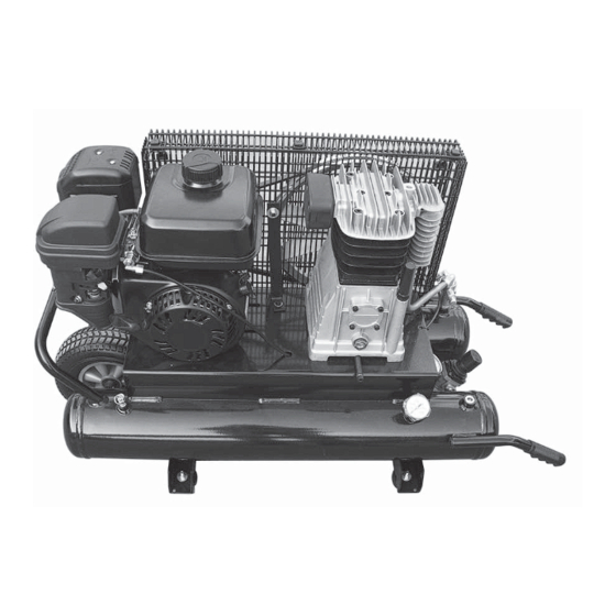
FEATURES PRODUCT SPECIFICATIONS Engine Displacement..........212 cc Lubrication ...............Oil Air Tank Capacity ............9 gal. Gauges ............1.5 in. diameter Air Pressure ............135 PSI max. Net Weight ...............150 lbs. Air Delivery ...........11 SCFM @ 40 PSI ............9.5 SCFM @ 90 PSI Fig. - Page 10 FEATURES KNOW YOUR AIR COMPRESSOR SAFETY VALVES See Figure 1. Safety valves aid in preventing system failures by relieving Before attempting to use this product, familiarize yourself system pressure when compressed air reaches a pre-determined with all operating features and safety rules. pressure level.
-
Page 11: Assembly
FEATURES When using the compressor for spray painting, isolate the PRESSURE VESSELS compressor as far away from the work area as practical, Air receiver tanks and other pressure containing vessels employing extra air hose rather than an extension cord. must be equipped with a properly sized pressure relief Warranty will be void if a failure is determined to be caused valve, pressure gauge, and a tank drain. - Page 12 ASSEMBLY is responsible for providing a suitable foundation & rubber foot mounting where necessary. DANGER! Under no circumstances should a compressor be HIGH ALTITUDE APPLICATIONS used in an area where toxic, volatile, or corrosive Refer to the engine manufacturer’s recommendations for agents are used or stored near the compressor.
-
Page 13: Operation
OPERATION DRAINING THE TANK See Figure 3. The drain valve is located on the underside of each air DRAIN tank(s). The compressor can be tilted in the direction of the VALVE drain valve in order to allow removal of tank moisture. To help prevent tank(s) corrosion and keep moisture out of the air used, the tank(s) of the compressor should be drained daily. - Page 14 OPERATION Drain moisture from the air tank(s). Never attempt WARNING: to drain the tank(s) without first relieving the system pressure (using the instruction found in Draining the Do not allow familiarity with tools to make you careless. Remember that a careless fraction of a second is Tank).
-
Page 15: Operation
OPERATION TANK REGULATOR PRESSURE WARNING: PRESSURE PRESSURE OUTLET REGULATOR GAUGE GAUGE KNOB Your tool may require more air consumption than this air compressor is capable of providing. Check the tool manual to avoid damage to the tool or risk of personal injury. -
Page 16: Maintenance
MAINTENANCE MAINTENANCE SCHEDULE WARNING: Refer to the gas engine owner’s manual for maintenance When servicing, use only identical Harbor Freight Tools procedures to be performed on the engine. If the unit is replacement parts. Use of any other parts may create a used in an excessively dirty or dusty environment, check hazard or cause product damage. - Page 17 MAINTENANCE Yearly Inspect the tank yearly for rust, pin holes, or other imperfections that could cause it to become unsafe. Avoid using solvents when cleaning plastic parts. Most plastics are susceptible to damage from various types of DRAIN commercial solvents and may be damaged by their use. PLUG Use clean cloths to remove dirt, dust, oil, grease, etc.
- Page 18 MAINTENANCE BELT ALIGNMENT & ADJUSTMENT See Figures 7 - 8 - 9 - 10. Drive belts tend to stretch with normal use and require adjustment periodically (check monthly). In order to adjust the drive belt, the belt guard must be removed. In order to remove the belt guard, follow the instructions shown in figures 7 - 8.
- Page 19 MAINTENANCE TIGHTENING OF HEAD TENSION RODS See Figure 11. Check that all screws (in particular those of the head of the unit) are tightly drawn up. HEAD TENSION The check must be carried out prior to the first compressor starting. And after the first hour of work. Tightening values for the tension rods of the head: Nm min.
- Page 20 MAINTENANCE PILOT VALVE ADJUSTMENTS See Figures 13 - 14. All adjustments made to the pilot valve must be performed Step 1. by a qualified technician. The adjustments must be made while the unit is operating, therefore, extreme caution must be taken while working on the unit. Observe all necessary precautions.
-
Page 21: Troubleshooting
TROUBLESHOOTING Read and understand all the safety rules listed in this manual and follow all procedures listed in MAINTENANCE before making repairs. Refer to the gas engine owner’s manual for troubleshooting the gas engine. Problem Possible Cause Solution Motor hums or runs slowly when first Lubricant being used is too heavy. - Page 22 TROUBLESHOOTING Problem Possible Cause Solution Excessive lubricant consumption and/ Crankcase overfilled with lubricant. Drain lubricant. Refill to proper or excessive lubricant in hose. level with proper lubricant (refer to LUBRICATION). Lubricant leaks. Tighten bolts on compressor to proper torque or replace gaskets. Worn piston rings.
-
Page 23: Troubleshooting
TROUBLESHOOTING Problem Possible Cause Solution Compressor overheats. High ambient temperature, poor Increase ventilation with cooler air. ventilation. Dirty cylinder and head cooling fins. Clean all outer surfaces of the compressor. Unit is undersized for application. Re-evaluate application requirements; re-size compressor unit if necessary. Insufficient lubrication. -
Page 24: Warranty
The brass components of this product contain lead, a chemical known to the state of California to cause birth defects (or other reproductive harm). (California health & safety code § 25249.5, et seq.) SKU 67696 SKU 68140 For technical questions, please call 1-800-444-3353.
Need help?
Do you have a question about the 68140 and is the answer not in the manual?
Questions and answers
Looking for a connecting rod for 9 gallon wheelbarrow central pneumatic compressor pump. Model 68140
To find a connecting rod for the Central Pneumatic 68140 9-gallon wheelbarrow compressor pump, you should contact Compressor Support at 1-800-444-3353. Have your model and serial numbers ready, which can be found on the product’s data label.
This answer is automatically generated