
Related Manuals for FRIEDLAND SA5


Summary of Contents for FRIEDLAND SA5
- Page 1 6 Zone Communicating Wirefree Alarm System ENTER Installation & Operating Manual...
-
Page 2: Part-Arming The System: Part-Arm
FOREWORD All devices in this wirefree Alarm System are designed Note: The effect on the range of multiple walls is and manufactured to provide a high standard of cumulative. e.g. if there are two brick walls in the way, security protection and long, reliable service. the range will be reduced by up to 40% by each wall. -
Page 3: Table Of Contents
CONTENTS EXTERNAL SOLAR SIREN General Information KIT CONTENTS Positioning the Solar Siren INTRODUCTION AND OVERVIEW Installing and Configuring the Solar Siren Multiple Users Power-up the Solar Siren System Arming EXTERNAL CONNECTIONS Entry/Exit Delay TESTING THE SYSTEM Zones FACTORY SETTINGS Zone Lockout Reset Factory Settings Quick Set Final Exit Set Zone... -
Page 4: Kit Contents
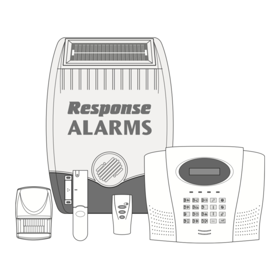
KIT CONTENTS The Alarm System should contain the following devices: 1 x Solar Siren 1 x Control Panel 1 x Remote Control 2 x PIR Movement Detectors 2 x Magnetic Contact Detectors Also included: PIR Movement Detector Telephone Connection Lead Power Supply Adaptor Installation &... -
Page 5: Introduction And Overview
INTRODUCTION AND OVERVIEW MULTIPLE USERS If a detector on a zone with its Entry-Delay enabled is triggered, then an alarm will not sound until the Entry- The system allows for up to 6 Users and a Master Delay period has expired. This allows time for the user User to be configured. -
Page 6: Zone Lockout
CHIME 3 times then that zone will be ‘Locked Out’ and any further alarm signals from that zone will be ignored until Chime is a low security facility for use when the system the system is disarmed. is Standby mode. If the Chime feature is ON, and a detector on a zone that has its Chime function enabled Note: The ‘Zone Lockout’... -
Page 7: Answerphone
sequence is cancelled/acknowledged by the recipient. The jamming detection circuit is designed to permanently scan for jamming signals. However, it is For example, the Latch Key facility is useful to inform possible that it may detect other local radio interference parents that a child has returned from school and operating legally or illegally on the same frequency. -
Page 8: Planning And Extending Your Alarm System
PLANNING AND EXTENDING YOUR ALARM SYSTEM Before attempting to install your Alarm System it is TYPICAL INSTALLATION important to study your security requirements and plan The following example below shows typical property your installation. incorporating the suggested positions for the Siren, PIR and Magnetic Contact Detectors. -
Page 9: Remote Control Unit
Typical Installation using only detectors • PART-ARM 1 is configured with a 30 second exit supplied: delay and operates with detectors on zones 1 to 4 only. 1. Place the 1 Magnetic Contact Detector (configured • PART-ARM 2 is OFF. on zone 1) on the front door. -
Page 10: Configuring The Remote Control
Any number of Remote Control Units can be used with Testing the Remote Control: your system, providing they are all coded with the same 6. Press the button. The Transmit LED should system House Code. illuminate while the button is pressed and extinguish within 1 second of releasing the button The Remote Control is powered by a CR2032 type Lithium cell which under normal conditions will have an... -
Page 11: Mounting The Control Panel
������������ ����������� ��������������� ������������� ������������� �������� ����������� ������������� ����������� ���������� ������������ ���������� ���������� ���������� ���������� ����������� ����������� ������������ ���� ������������ ������� ������������ ����������� Inside View of Control Panel 5. The Control Panel must be located within reach Note: The wall plugs supplied with the product are not of a mains socket. -
Page 12: Configuring The Control Panel House Code
7. Ensure that the “Reset” and the “Hard-Wired Siren Note: If the Control Panel Tamper alarm sounds during tamper detect” jumper links are set in the OFF position. the installation reset the alarm by pressing ������ ������ ���� ���� User Access Code on the Control Panel. -
Page 13: Testing The Control Panel & Remote Control
To conserve power and maximise battery life the PIR 5. Press to save the new setting. Detector will only detect movement if there has been 6. Press to return to Standby. no movement detected within the previous 2 minutes, (this is known as the detectors “sleep period”). TESTING THE CONTROL PANEL &... -
Page 14: Installing And Configuring The Pir Detector
When deciding upon the mounting position for the 2. Carefully drill out the required mounting holes in the detector the following points should be considered to rear cover using a 3mm drill according to whether the ensure trouble free operation: unit is being mounted in a corner or against a flat wall. - Page 15 8. To select the required sensitivity, set DIP switch 5 of Testing the PIR Detector: SW3 as follows: 12. Ensure that the LED indicator has stopped flashing rapidly. ON = HIGH sensitivity OFF = LOW sensitivity 13. Use the buttons to scroll through the menu until ‘WALK TEST’...
-
Page 16: Magnetic Contact Detectors
MAGNETIC CONTACT Do not fix the Detector onto or very close to metalwork (i.e. radiators, water pipes, etc.) as this could affect the DETECTORS radio range of the device. The Magnetic Contact Set comprises 2 parts; Detector On PVC Door/Window frames, it may be necessary to and Magnet. - Page 17 3. If fixing the detector with screws, first remove the 6. Configure the alarm zone which the detector will battery holder by carefully tilting up the end and pulling operate on with DIP switches 9-11 as follows: away from the printed circuit board (PCB). DIP 9 DIP 10 DIP 11...
-
Page 18: External Solar Siren
POSITIONING THE SOLAR SIREN Tamper’ will be displayed. The Siren should be located as high as possible in a 12. Open the door/window to remove the Magnet from prominent position on an external wall so that it can be the Detector. easily seen and heard. -
Page 19: Installing And Configuring The Solar Siren
�������������� ����������� ����������� ����������������� ����� ���������� ����� ���������������� � ������ �� ������ ������������������ �� �� ������� ���� �������������� ������������ ������� ���������� ���������������� ���������������� ������������������������� �������������� ������������������� ������������ ���� ����� ����������������� ���� ����� INSTALLING AND CONFIGURING THE 8. Under the cover you will find a series of 9 DIP SOLAR SIREN switches. -
Page 20: Power-Up The Solar Siren
Testing the Solar Siren: 12. If for any reason you need to disable the Siren, remove jumper link P3 on the circuit board. This 4. Use the buttons to scroll through will prevent the Siren from sounding during an the menu until ‘ALARM TEST’ is displayed and press alarm condition. -
Page 21: Testing The System
TESTING THE SYSTEM The Control Unit incorporates a terminal block for connection of hard-wired zones (7-10) and a wired The Control Panel has a built in test facility to enable Siren unit. The connection terminal block is located inside the Control Panel behind the front cover. To you to test the system at any time. -
Page 23: Factory Settings
FACTORY SETTINGS VOICE DIALLER TEST 1. Scroll through the top level Test Mode menu until USER SETUP ‘VOICE DIALER TEST’ is displayed and press User Access Codes: Users 1-6: Not programmed Master User: 1234 2. If the Voice Dialler is enabled it will be activated Latch Key messages: Not programmed and will follow the normal calling process. -
Page 24: Reset Factory Settings
PROGRAMMING RESET FACTORY SETTINGS INSTRUCTIONS 1. Press User Access Code With the system in Standby (i.e. with the display showing “DISARM READY”). This puts the system into Test Mode. Press 2. Undo the Control Panel cover fixing screws and Master User Access Code open the cover. -
Page 25: User Setup
STANDBY MODE PROGRAM MODE Code: Master User Access Code 7. PART ARM 8. TIME & DATE 9. LATCHKEY SETUP SETUP SETUP 8-1 Date 8-2 Time DD/MM/YY 000 HH/MM/SS Save & exit Exit without saving HH/MM/SS Enter new system line USER SETUP Telephone Application Setup. - Page 26 USERS 1-6 To change the setting press Default setting: not programmed Type in a new 4 digit Access Code, and then Scroll through the menu until the required User ‘USER Press to save and exit, or _ SETUP’ is displayed and press Press to exit without saving.
-
Page 27: System Setup
SYSTEM SETUP ������� ���� ����� �� ������ ����� ��� ����� ����� ��� �������� ��� ���� ����� ��� ���� ������� ��� ����� �� ���� ���� ������ ���� ������ ��� ��� ��� ������ ������ �� ��������� ����� ������ �� ����� ����� ��������� ������... - Page 28 Scroll through the menu until ‘2-2-1 Status’ (and Detection’ (and the current setting) is displayed. the current setting) is displayed. To change the setting press To change the setting press Press to enable Jamming Detection, or Press to enable the Siren, or Press to disable Jamming Detection.
- Page 29 Scroll through the menu until ‘2-11 Dial Method’ (and REMOTE PHONE ACCESS AND CONTROL the current setting) is displayed. If enabled, this allows the system to be remotely controlled via the telephone. To change the setting press Default setting: OFF Scroll through the menu options, until the required setting is displayed.
-
Page 30: Zone Setup
ZONE SETUP The parameters in this menu allow each zones specific function to be configured. ������������ ����� ������������� ���������������� ������������ ������������ ������������� �������� ������������ ���������������� ���������������� ������� ��������������� ��������������� ������� �������� ��� ������ ������ ��������������� ��������������� ���������� �������� ���������� ��������� ����������������... - Page 31 24 Hour Intruder - used to provide 24 hour monitoring CHIME of areas requiring continuous security protection even This controls whether the zone will operate with Chime while the system is Disarmed, (e.g. gun lockers). Mode. Activation of any detector on a security zone will Default setting: OFF immediately initiate an Alarm.
- Page 32 PART-ARM 1 This controls whether the zone is active when Part-Arm 1 is armed. Default setting: zones 1-4: Zones 5-10: Scroll through the menu until ‘3-6 Z01 Part-Arm 1’ (and the current setting) is displayed. To change the setting press Press to enable the zone in Part-Arm 1, or Press...
-
Page 33: Voice Dialler Setup
VOICE DIALLER SETUP The parameters in this menu allow the setting of the systems Voice Dialler. It allows up to 4 phone numbers to be entered and the call routing sequence to be set by defining which number is called and the number of attempts made to contact each number. - Page 34 ALARM MESSAGE PLAY TIME CALL ROUTING This is the total time for which the alarm messages will This controls which phone numbers in the dialling be played & repeated by the Voice Dialler. sequence are enabled and will be called when the Voice Dialler is activated.
-
Page 35: Full Arm Setup
CALL ATTEMPTS Scroll through the menu until ‘5-1-1 Status’ (and the current setting) is displayed. This sets the maximum number of times that the dialler will attempt to contact each enabled telephone number To change the setting press in the call routing sequence. Press to enable the Exit-Delay, or Default setting: 3... -
Page 36: Part-Arm 1 Setup
PART-ARM 1 SETUP Press to save and exit, or The parameters in this menu control the systems Exit- Press to exit without saving. Delay period and the Entry/Exit Delay warning beeps Press to return to top level Part Arm 1 Setup during Part-Arm 1 mode. -
Page 37: Part-Arm 2 Setup
PART-ARM 2 SETUP Press to save and exit, or The parameters in this menu control the systems Exit- Press to exit without saving. Delay period and the Entry/Exit Delay warning beeps Press to return to top level Part Arm 2 Setup during Part-Arm 2 mode. -
Page 38: Time & Date Setup
TIME & DATE SETUP LATCH KEY SETUP The parameters in this menu allow the systems The parameters in this menu configures which users clock and calendar (required for the Event Log) to be the Latch Key feature operates with and the telephone configured. -
Page 39: Answerphone Setup
SELECTED-USERS SETUP ANSWERPHONE SETUP This configures the individual users that the Latch Key The parameters in this menu allow the systems operates with when set to ‘Selected-Users’. answerphone facility to be configured and the greeting message to be recorded. Default setting: OFF Note: For the answerphone to operate correctly the Scroll through the menu until ‘9-2 SELECTED USER “Dial Method”... -
Page 40: Remote Manager Setup
REPLAY ANSWERPHONE GREETING Press to save and exit, or Scroll through the menu until ‘10-3 Replay Greeting’ is Press to exit without saving. displayed. To replay the recorded greeting message press UNIT ID Scroll through the menu until ‘11-2 Unit ID No:’ (and REMOTE MANAGER SETUP the current setting) is displayed. -
Page 41: Operating Instructions
OPERATING INSTRUCTIONS then the first enabled phone number in the dialling sequence will be called and the recorded alarm When leaving the premises, the system must be Armed. message will be replayed for the programmed “Play However, before doing so, check that all windows are Time”... -
Page 42: Quick Set
PERSONAL ATTACK (PA) ALARM If when the system is disarmed the ‘ALARM MEM’ LED is flashing and the panel beeps every 10 seconds, this An alarm can be immediately triggered at any time indicates that an alarm has occurred. (whether the system is Armed or Disarmed) in the event of threat or danger by activating a Personal To stop the LED flashing and panel beeping either Attack (PA) switch on either the Remote Control or the... -
Page 43: Leaving A Voice Memo Message
Press to access the Event Log, (from Standby Press to delete the message Mode only). Press to re-confirm deletion of the message. The Event Log will automatically display each event in Note: Press at either stage to cancel delete and turn starting with the most recent. -
Page 45: Battery Monitoring
Press to switch the Siren between Service Mode PIR Movement Detector and Operating Mode. LED 5 will illuminate to show that Under low battery conditions the LED behind the the appropriate signal is being transmitted. detector lens will flash when movement is detected to indicate that the battery needs to be replaced. -
Page 46: Maintenance
MAINTENANCE CONTROL PANEL The rechargeable batteries have a typical life in excess Your Alarm System requires very little maintenance. of 3 to 4 years and need no maintenance during this However, a few simple tasks will ensure its continued period, provided they are kept charged. The batteries reliability and operation. -
Page 47: Alarm Record
ALARM RECORD Complete the following information during installation for future reference, when adding to your system and to assist trouble shooting. Zone Settings Final- Exit / Detector Entry Part- Part- Zone Location Type Chime Walk- Type(s) Delay Arm 1 Arm 2 Through settings You may make a note of your User Access Codes and Installer Access Code below. -
Page 48: Trouble Shooting
TROUBLE SHOOTING Symptom / Recommendation Siren not responding to Control Panel. Control Unit not working – Power LED OFF or flashing. 1. Ensure ‘House Code’ is correctly set to the same code as all other system devices. 1. Mains power failure - check if other electrical circuits are operable. - Page 49 5. Ensure that detector is mounted the correct way up, (i.e. Voice-Dialler Not Responding to Alarm with detection window at the bottom). 1. Telephone line not connected or faulty - check phone line 6. Ensure that the detector is mounted at the correct height, with another phone.
-
Page 50: Extending Your Alarm System
If an item develops a fault, the product must be returned to the point of sale with: 1. Proof of purchase. 2. A full description of the fault. 3. All relevant batteries (disconnected). Friedland is a trademark of Novar ED&S. -
Page 52: Component Specification
Monday to Friday) • Low Battery Indicator Novar Electrical Devices and Systems are Quality Assurance Registered to BS EN ISO9001 : 2000, by Asta. Friedland, Novar Electrical Devices and Systems. The Arnold Centre, Paycocke Road, Basildon, Essex SS14 3EA. UK. 45173PL Ed.3...
Need help?
Do you have a question about the SA5 and is the answer not in the manual?
Questions and answers
we think the rechargeable battery needs replacing , what is it and where can I GET A REPLACEMENT
The rechargeable battery type for the FRIEDLAND SA5 is ULTRAMAX NP1.3-6, 6V 1.3Ah. A replacement can be found on Amazon under the listing "Response Alarms ULTRAMAX NP1.3-6 6v 1.3Ah Replacement Response Alarm Battery/SA Range."
This answer is automatically generated