
Subscribe to Our Youtube Channel
Related Manuals for FRIEDLAND Bronze


Summary of Contents for FRIEDLAND Bronze
- Page 1 Wirefree Security Alarm Bronze / Silver Friedland ™ Installation & Operating Manual...
- Page 2 FOREWORD devices in this Wirefree Alarm System are ceilings, reinforced PVC doors etc) placed between designed and manufactured to provide long reliable the transmitter and Receiver device will reduce the service. The system is designed for ease of radio range. installation using only conventional domestic tools.
-
Page 3: Table Of Contents
CONTENTS KIT CONTENTS MAGNETIC CONTACT DETECTORS Positioning the Magnetic Contact Detectors INTRODUCTION AND OVERVIEW Installing and Configuring the Magnetic System Arming Contact Detectors Entry/Exit Delay Testing the Magnetic Contact Detectors Alarm Lockout ADDING A NEW PIR OR MAGNETIC (MAG) Tamper Protection DOOR / WINDOW CONTACT DETECTOR Jamming Detection TO THE SIREN... -
Page 4: Kit Contents
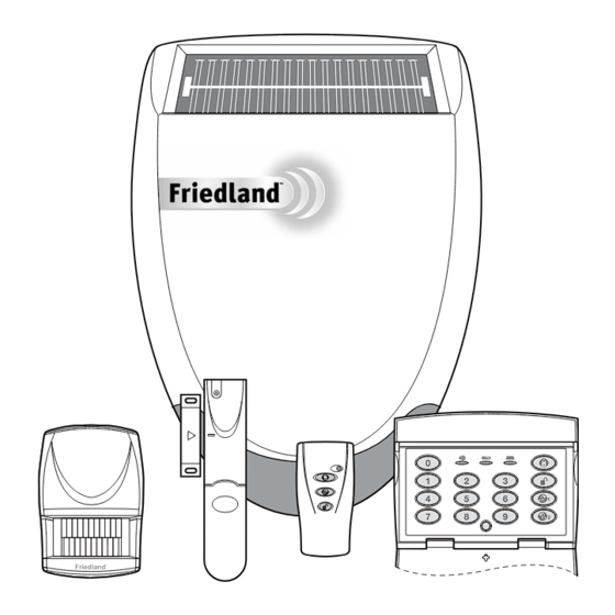
KIT CONTENTS The Alarm System should contain the following devices. Alarm System SK1 Bronze SK2 Silver Solar Siren Remote Control PIR Movement Detectors Magnetic Contact Detectors Remote Control Keypad Also included: Siren Mounting Template Installation & Operating Manual Installation DVD... -
Page 5: Introduction And Overview
INTRODUCTION AND OVERVIEW SYSTEM ARMING JAMMING DETECTION The system has an Instant-Arm and Delay-Arm mode. order to detect any attempts to illegally jam the radio channel used by your alarm system, a special If the system is armed in Instant-Arm mode then all jamming detection function is incorporated into the detectors will immediately become fully armed. -
Page 6: Alarm System
The following example below shows a typical all within radio range of the Siren. property incorporating the suggested positions for Remote Keypad Remote Control Friedland ™ SHED PIR Movement Detector Back Door KITCHEN DINING... -
Page 7: Remote Control Unit
REMOTE CONTROL UNIT The Remote Control Unit(s) is used to Arm in either Instant-Arm or Delay-Arm modes and to Disarm the system. Battery Clip Transmit LED Battery Instant-Arm Slide up Delay-Arm to operate Disarm Personal Attack Switch TESTING THE REMOTE CONTROL Press the button. -
Page 8: Positioning The Keypad
The Keypad is powered by a PP3 Alkaline battery installation is complete, (see page 19). If the Siren which under normal conditions will have an expected Unit is being installed and configured for the first life of approximately 1 year. When the battery level time refer to pages 10 - 12. -
Page 9: Changing The User Access Code
Connect the PP3 alkaline battery to the battery Enter a new User Access Code of your choice: clip and set the jumper link J1 shown in Fig. 1a which is what the keypad is set to normally. New User Access Code Replace the rear cover and refit fixing screws. -
Page 10: External Solar Siren
Set the jumper link as shown in Fig. 1b. (below). POSITIONING THE SOLAR SIREN The Siren should be located as high as possible in Refit the battery and test it by entering the a prominent position on an external wall so that it Administrator Access Code 1234. -
Page 11: Power-Up Of The Solar Siren
Siren Switch SW3 ALARM TIME Tamper Switch ALARM TIME ALARM SOUND ALARM SOUND Learn BEEP SOUND BEEP SOUND C.U. OR SIREN Learn C.U. OR SIREN Switch 7.5 Volt DC charging 9 Volt startup adaptor input battery 6 Volt 1.2Ah Wall mounting plate rechargeable battery POWER-UP OF THE SOLAR SIREN... -
Page 12: Addinga New Remote Control Or Keypad To The Solar Siren
ADDING A NEW REMOTE CONTROL OR To program the Remote Keypad’s ID code into KEYPAD TO THE SOLAR SIREN the Siren repeat step 11: a) Press IMPORTANT: order to communicate with the New Keypad User Access Code Siren, the ID code of the Remote Control / Keypad needs to be learned by the Siren. -
Page 13: Mounting The Solar Siren On To The Wall
MOUNTING THE SOLAR SIREN ON PASSIVE INFRA-RED (PIR) TO THE WALL MOVEMENT DETECTORS Hold the clear plastic mounting template supplied Detectors detect movement in a protected area in position and mark the positions of the four by detecting changes in infra-red radiation levels mounting holes. -
Page 14: Installing And Configuring The Pir Detectors
INSTALLING AND CONFIGURING THE PIR DETECTORS Note: adding a PIR Detector to an installed system, ensure that the Siren is in Service Mode before 10 11 commencing installation, (see page 19). Remember Detector Range (metres) to switch the Siren back to Operating Mode after installation is complete, (see page 19). -
Page 15: Testing The Pir Detectors
to normal operation. On initial installation the detector should be configured into Walk Test ready for testing, (i.e. Pressing down SW1 for 2 seconds). SW1 (Test Mode) SW1 (Test Mode) Press for 2 seconds to Test Mode activate Walk Test mode Sensitivity SW2 (Tamper) SW3 (Sensitivity) -
Page 16: Magnetic Contact Detectors
MAGNETIC CONTACT Ensure that the position selected for the Magnetic Contact Detector is within effective range of the Siren. DETECTORS Do not fix the Detector onto or very close to The Magnetic Contact Set comprises of two parts; metalwork (i.e. radiators, water pipes, etc) as this a Detector and a Magnet. - Page 17 The Detector and Magnet should be mounted Switch SW3 is used to enable / disable the using the double sided adhesive pads or screws internal / external wired magnetic contact. provided. Note: If mounting the device using the adhesive 11mm pads, ensure that the mounting surfaces are Location of Key-hole Screw...
-
Page 18: Testing The Magnetic Contact Detectors
TESTING THE MAGNETIC CONTACT ADDING A NEW PIR OR DETECTOR MAGNETIC (MAG) DOOR / Remove battery cover to activate the tamper WINDOW CONTACT switch. DETECTOR TO THE SIREN As the button is released the LED indicator will illuminate for approximately 1 second to show IMPORTANT: order to communicate with the that the tamper switch has been triggered and a... -
Page 19: Deleting All Devices From The System
b) Confirm the new device ID code by The siren can be switched between Service Mode activating the Tamper Switch again on the and Operating Mode using any linked Remote PIR/MAG detector within 15 seconds. Control or Keypad as follows: The siren will produce three short low Remote Control: volume beeps and the Indicator / Learn... -
Page 20: Testing The System
TESTING THE SYSTEM The system should be tested at regular intervals (at Stop the alarm and Disarm the system by least every 3 months), to ensure that it is operating entering your User Access Code followed by the correctly. ‘DISARM’ button on the Keypad. Before commencing testing please ensure the following: User Access Code... -
Page 21: Operating Instructions
OPERATING INSTRUCTIONS When leaving the premises, the system must be ARMING THE SYSTEM IN Armed. However, before doing so, check that all INSTANT- ARM MODE windows are closed and locked, all protected doors The system can be Armed in Instant mode by using are closed and PIR Detectors are not obstructed. -
Page 22: Disarming The System
DISARMING THE SYSTEM The Alarm will sound until the set alarm duration time expires or the system is Disarmed from the The system can be Disarmed using either the Remote Control or Keypad. Remote Control or the Keypad as follows: SIREN SERVICE MODE Remote Control:... - Page 23 Remote Keypad When the battery is low the ‘low-batt’ LED on the keypad will be illuminated. Note: The Keypad will retain your User Access Code setting for approximately 15 seconds whilst the battery is removed and replaced. If the battery is left disconnected for a longer period, or has been allowed to run completely flat your User Access Code will revert to the factory set code of “1 2 3 4 ”...
-
Page 24: Maintenance
MAINTENANCE Your Alarm System requires very little maintenance. operating and triggering an alarm, (see page 19). However, a few simple tasks will ensure its continued The Siren must be switched back into Operating reliability and operation. Mode, otherwise the system cannot be Armed. IMPORTANT: If, for any reason you have to DETECTORS, REMOTE CONTROL completely power-down the system (e.g. -
Page 25: Trouble Shooting
TROUBLE SHOOTING Symptom / Recommendation Siren immediately sounds when system Siren rechargeable battery discharged: armed. a. Clean Solar Panel. Siren tamper switch activated - adjust tamper b. Check age of rechargeable battery - replace plunger and ensure that switch fully closes when if at end of useful life. - Page 26 Movement Detector not detecting a 5. If there is no additional wired Magnetic Contact person’s movement. connected ensure switch SW3 is set to (INT.) internal contact ON. Ensure the battery clip is securely connected. 6. If an additional wired Magnetic Contact is Ensure ‘ID code’...
-
Page 27: Extending Your Alarm System
If an item develops a fault, the product must be returned to the point of sale with: 1. Proof of purchase. 2. A full description of the fault. 3. All relevant batteries (disconnected). Friedland is a trademark of Novar ED&S. -
Page 28: Component Specification
Battery life >1 year Monday to Friday. Calls charged at Low battery indicator service providers national rate). Friedland, Novar Electrical Devices and Systems Limited. (A Honeywell Company) The Arnold Centre, Paycocke Road, Basildon, Essex SS14 3EA. UK www.friedland.co.uk. 51062PL Ed.4...
Need help?
Do you have a question about the Bronze and is the answer not in the manual?
Questions and answers