Table of Contents
Advertisement
™
WARRANTY
®
Top Flite
Model Manufacturing Co. guarantees this kit to be free from defects in both material and
workmanship at the date of purchase. This warranty does not cover any component parts damaged by use
or modification. In no case shall Top Flite's liability exceed the original cost of the purchased kit.
Further, Top Flite reserves the right to change or modify this warranty without notice.
In that Top Flite has no control over the final assembly or material used for final assembly, no liability shall be
assumed nor accepted for any damage resulting from the use by the user of the final user-assembled
product. By the act of using the user-assembled product, the user accepts all resulting liability.
If the buyer is not prepared to accept the liability associated with the use of this product, the buyer is
advised to return this kit immediately in new and unused condition to the place of purchase.
To make a warranty claim send
the defective part or item to
Hobby Services at this address:
Include a letter stating your name, return shipping address, as much contact information as possible (daytime
telephone number, fax number, e-mail address), a detailed description of the problem and a photocopy of the
purchase receipt. Upon receipt of the package the problem will be evaluated as quickly as possible.
READ THROUGH THIS MANUAL BEFORE STARTING CONSTRUCTION. IT CONTAINS IMPORTANT INSTRUCTIONS AND WARNINGS CONCERNING THE ASSEMBLY AND USE OF THIS MODEL.
Entire Contents © 2013 Hobbico, Inc.
Hobby Services
3002 N. Apollo Dr. Suite 1
Champaign IL 61822 USA
INSTRUCTION MANUAL
Top Flite Models Champaign, IL
airsupport@top-flite.com
SPECIFICATIONS
Wingspan:
Wing Area:
Weight:
Wing
Loading:
Length:
Radio:
Engine:
Ph: (217) 398-8970, Ext. 5
Fax: (217) 398-7721
86-1/2 in [2195mm]
1325 in
2
[85.5 dm
2
]
22 – 24 lb
[9.98–10.88 kg]
2
38– 42 oz/ft
2
[116–128 g/dm
]
72 in [1830 mm]
6– 7 channel
3.0–4.0 cu in [50–65cc]
spark ignition gas
TOPA0708 Mnl
Advertisement
Table of Contents

Related Manuals for Top Flite Models Spitfire


Summary of Contents for Top Flite Models Spitfire
-
Page 1: Instruction Manual
INSTRUCTION MANUAL Top Flite Models Champaign, IL ™ Ph: (217) 398-8970, Ext. 5 Fax: (217) 398-7721 airsupport@top-flite.com WARRANTY SPECIFICATIONS ® Top Flite Model Manufacturing Co. guarantees this kit to be free from defects in both material and Wingspan: 86-1/2 in [2195mm] workmanship at the date of purchase. -
Page 2: Table Of Contents
TABLE OF CONTENTS INTRODUCTION ......2 ASSEMBLE THE WINGS ..... 7 Balance the Model Laterally. -
Page 3: Important Safety Precautions
such as a kit box cover from a plastic model, a photo, or 6. While this kit has been fl ight tested to exceed normal engines deposit little exhaust residue on the model. a profi le painting, etc. If the photo is in black and white, use, if the plane will be used for extremely high stress Among other engines, this model was test fl... -
Page 4: Radio Equipment
RADIO EQUIPMENT The battery voltage should be checked before every air tank in this model. A small, 12V electric pump is fl ight to be certain it has enough “charge”. recommended and can be purchased at any automotive The radio equipment and number of channels required or hardware store. -
Page 5: Covering Tools
❍ Drill ❍ Switch & Charge Jack Mounting Set this information visit the web site at www.top-fl ite.com and click on “Technical Data.” Due to manufacturing ❍ Drill bits: 1/16" [1.6mm], 5/64" [2mm], 3/32" (GPMM1000) tolerances which will have little or no effect on the way ❍... -
Page 6: Replacement Parts List
be charged sales tax. If ordering via fax, include a Visa ® REPLACEMENT PARTS LIST COMMON ABBREVIATIONS or MasterCard ® number and expiration date for payment. Stab = Horizontal Stabilizer TOPA1920..…Wing Kit Mail parts orders Hobby Services Fin = Vertical Stabilizer TOPA1921..…Fuselage Kit and payments by 3002 N Apollo Drive, Suite 1... -
Page 7: Assemble The Wings
❏ ❏ ASSEMBLE THE WINGS MOUNT THE AILERON SERVOS 3. Use 6-minute epoxy to glue the two blocks to ❏ ❏ the bottom of the servo hatch over the embossed servo 1. Carefully remove the left aileron servo hatch Start with the left wing so the assembly matches the block locations. -
Page 8: Install The Flap Servos
secure the servo mounting blocks to the aileron servo INSTALL THE FLAP SERVOS the 4-40 metal clevis, threaded 12 turns onto a 4-40 hatch. Use thin CA to harden the screw threads x 12" [304mm] metal pushrod. Attach the clevis to the aileron servo arm 5/8"... -
Page 9: Mount The Retracts
MOUNT THE RETRACTS Install the left retract fi rst. HOW TO SOLDER 1. Roughen the end of the pushrod with coarse sandpaper where it is to be soldered. Use denatured alcohol or other solvent to thoroughly clean the pushrod. 2. Apply a few drops of soldering fl ux to the end of the pushrod, then use a soldering iron or a torch ❏... - Page 10 ❏ ❏ 9. Mount the retract cover to the wing with fi ve #2 x 3/8" sheet metal screws and fi ve #2 fl at washers. Use thin CA to harden the holes. ❏ ❏ ❏ ❏ 6. Route the pressure tubing through the ribs and ❏...
-
Page 11: Join The Wing
with a 5/32 [4mm] drill bit. Secure the landing gear the wing dowels and wing bolts. Add several strips of cover to the retract with two 6-32 x 1/4" machine screws masking tape to tightly hold the wings together as you and #6 fl... -
Page 12: Assemble The Fuselage
ASSEMBLE THE FUSELAGE and the fuselage. Insert the end of the aluminum tubes with epoxy on them into the stabilizer and press the Firmly pull on the elevators to check that the hinges stabilizer against the fuselage. Wipe off any excess are securely glued. -
Page 13: Install The Elevator & Rudder Servos
Use the toothpick to apply epoxy to the ends of the rudder hinges that go into the fi n. Insert each hinge into the fi n and wipe away any excess epoxy that squeezes out of the hole. Apply epoxy to the other end of the hinges. Join the rudder to the fi... - Page 14 ❏ 5. Cut the .018 x 84" [.45 x 2100mm] braided cable in half. Slide a small copper tube (called a swage) over one end of both braided cables, then guide the end of the cable back through. ❏ 2. Slide the tail gear wire into the fi xed tail gear frame. Secure the tail gear wire in the frame with a second 3.5mm wheel collar and 2.5 x 4mm machine screw.
- Page 15 ❏ ❏ ❏ 11. Drill two 3/32" [2.4mm] holes through the bottom 14. Thread a 4-40 nut and a 4-40 metal clevis on 16. The tail gear cover can be permanently installed rails for the tail gear. Mount the tail gear to the bottom rail to each of the 4-40 rigging couplers.
-
Page 16: Install The Engine
❏ 18. Slide a 3.5mm wheel collar followed by the tail wheel and a second wheel collar on the tail gear wire. ❏ Apply a drop of threadlocker to the threads of the 2.5 2. Drill a 13/64" [5mm] hole through the fi rewall at x 4mm machine screws. - Page 17 Thread the other end ¾" [19mm] into the end of the throttle pushrod tube. The L-bend makes it easier to thread in. ❏ 13. Cut off the L-bend from the 2-56 x 6" [152mm] pushrod. Insert the throttle pushrod into the throttle outer pushrod tube.
-
Page 18: Install The Air Retract Controls
where it crosses the servo arm 3/8" [9.5mm] from the center of the servo. ❏ 18. Plug the throttle and choke servo into the receiver. ❏ 16. Install the throttle and choke servos in the servo Position the throttle stick so that it is centered on the tray. - Page 19 ❏ 4. Test fi t the retract servo tray and receiver tray in the fuselage. Drill a 1/16" [1.6mm] pilot hole in throttle servo tray, using the eight mounting holes as guides. Attach the retract servo tray and receiver tray with #2 x 3/8"...
-
Page 20: Install The Ignition System
❏ 2. Wrap the ignition battery in foam rubber. Secure it to the top of the engine box with a hook and loop strap. Connect the plug from the ignition battery to the ignition switch. Secure the connection with a piece of heat shrink tubing. -
Page 21: Assemble And Install The Fuel Tank
onto the other end of the two short tubes. Bend the vent tube and connect the pickup and fueling/defueling lines (not included) to the short tubes. Connect the clunks to the lines and secure the lines to the clunk and brass tubing with the small tie straps. -
Page 22: Install The Cowl
❏ INSTALL THE COWL 5. Use 320 grit sandpaper to sand the inside of the cowl at the eight screw hole locations. Also, sand one side of the eight aluminum discs. Clean the disc and the inside of the cowl with denatured alcohol. ❏... - Page 23 ❏ ❏ ❏ 7. Position the radiators on the bottom of the wing, 8. Glue the plywood rudder spacer to the back of 9. Apply the instrument panel decal to the plywood behind the retract and perpendicular to the root of the the plastic rudder pedal.
- Page 24 ❏ 12. Trim the right cockpit side to fi t. The top of the cockpit should set on the top of the fuselage side. ❏ 15. Sand the bottom center of the seat and the top of the seat pedestal. Clean the area with denatured alcohol and glue the seat to the pedestal.
-
Page 25: Apply The Decals
APPLY THE DECALS ❏ 1. The decals are die-cut from the factory. ❏ 2. Be certain the model is clean and free from oily fi ngerprints and dust. Prepare a dishpan or small bucket with a mixture of liquid dish soap and warm water—about 1/2 teaspoon of soap per gallon of water. -
Page 26: Get The Model Ready To Fly
GET THE MODEL READY TO FLY 4-CHANNEL RADIO SETUP (STANDARD MODE 2) INSTALL THE PROPELLER RIGHT AILERON MOVES UP RUDDER LEFT AILERON MOVES MOVES DOWN RIGHT ❏ 1. Carefully balance the propeller and any spare propellers. An unbalanced propeller can be the single ❏... -
Page 27: Set The Control Throws
At the Servos These are the recommended control surface throws: The pushrod farther out The pushrod closer in LOW RATE HIGH RATE means More Throw means Less Throw Down Down 7/16" 7/16" 9/16" 9/16" [11mm] [11mm] [14 mm] [14 mm] 7°... -
Page 28: Balance The Model (C.g.)
system. If the plane is nose heavy, do not move the 5-13/16" [147mm] ignition battery aft closer to the receiver. 5-13/16" [147mm] ❏ 4. IMPORTANT: If you found it necessary to add any weight, recheck the C.G. after the weight has been installed. -
Page 29: Check List
❏ AMA R/C club fl ying sites and AMA sanctioned fl ying Keep all engine fuel in a safe place, away from high 9. Reinforce holes for wood screws with thin CA events. Fill out the identifi cation tag on page 33 and heat, sparks or fl... -
Page 30: Engine Safety Precautions
GENERAL three miles of any pre-existing fl ying site except in will also prevent accidental starting of the engine. This accordance with the frequency sharing agreement switch shall be readily available to both pilot and helper. 1) I will not fl y my model aircraft in sanctioned events, listed [in the complete AMA Safety Code]. -
Page 31: Flying
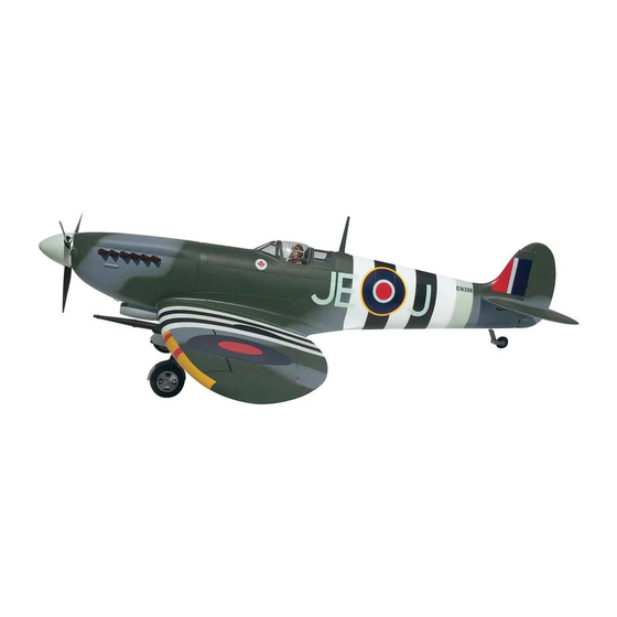
of the servos, size and loads on control surfaces, and FLYING TAKEOFF added features should be considered as an increase Before you get ready to takeoff, see how the model to these minimums. Batteries should be able to sustain The Giant Spitfi re ARF is a great-fl ying model that fl ies handles on the ground by doing a few practice runs at power to the onboard radio components for a minimum smoothly and predictably. -
Page 32: Takeoff
FLIGHT but those unfamiliar with landing giant-scale models are and has lost fl ying speed, hold up elevator to place the sometimes deceived by the model’s larger size. Larger tail on the ground, regaining tail wheel control. For reassurance and to keep an eye on other traffi c, it models often appear to be closer than they actually are. - Page 33 Left Retract Cover Right Retract Cover...
-
Page 35: Retract Cover Templates
notes:...
Need help?
Do you have a question about the Spitfire and is the answer not in the manual?
Questions and answers