Table of Contents
Advertisement
WARRANTY.....
material and workmanship at the date of purchase. This warranty does not cover any component parts
damaged by use or modification. In no case shall Top Flite's liability exceed the original cost of the
purchased kit. Further, Top Flite reserves the right to change or modify this warranty without notice.
In that Top Flite has no control over the final assembly or material used for final assembly, no
liability shall be assumed nor accepted for any damage resulting from the use by the user of the final
user-assembled product. By the act of using the user-assembled product, the user accepts all resulting
liability.
If the buyers are not prepared to accept the liability associated with the use of this product, they
are advised to immediately return this kit in new and unused condition to the place of purchase.
READ THROUGH THIS INSTRUCTION BOOK FIRST. IT CONTAINS IMPORTANT INSTRUCTIONS AND WARNINGS CONCERNING THE ASSEMBLY AND USE OF THIS MODEL.
Entire Contents © Copyright 1994
Top Flite Models guarantees this kit to be free of defects in both
Top Flite Models
P.O. Box 788
Urbana, IL 61801
Technical Assistance - Call (217) 398-8970
™
AT66P03 V1.1
Advertisement
Table of Contents

Related Manuals for Top Flite Models AT-6 Texan


Summary of Contents for Top Flite Models AT-6 Texan
- Page 1 ™ WARRANTY..Top Flite Models guarantees this kit to be free of defects in both material and workmanship at the date of purchase. This warranty does not cover any component parts damaged by use or modification. In no case shall Top Flite's liability exceed the original cost of the purchased kit.
-
Page 2: Table Of Contents
TABLE OF CONTENTS METRIC CONVERSIONS INTRODUCTION ........ Install the Engine ........38 Fit the Cowl to the Fuse ......39 Precautions..........3 Fit the Cowl to the Engine......40 DECISIONS YOU MUST MAKE EARLY Fit the Flaps ..........41 1” = 25.4 mm (conversion factor) IN THE BUILDING SEQUENCE ..4 Final fit the Retracts ........41... -
Page 3: Introduction
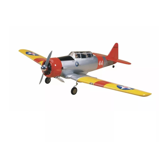
Your AT-6 Texan is not a toy, but a rather sophisticated, working model that functions very model, please call us at (217) 398-8970 and much like the full scale airplane. -
Page 4: Decisions You Must Make Early In The Building Sequence
.90 to 1.20 cu. in. 4-stroke and therefore offers the easiest installation. can be modified to suit any engine installation. The AT-6 Texan will fly well with any of More information on retracts can be found in the Part # TOPQ7901 the recommended engines. -
Page 5: Other Items Required
OTHER ITEMS REQUIRED Razor Plane (Master Airscrew) The full size AT-6 that was modeled for Pliers this kit is a restored Navy SNJ-3. We used Four to six channel radio with 4 to 7 servos. Screw Drivers documentation and photos available from Frank Engine (see page 4) T-Pins (short &... -
Page 6: Die-Cut Patterns
DIE-CUT PATTERNS... - Page 7 DIE-CUT PATTERNS...
-
Page 8: Get Ready To Build
GET READY TO BUILD 1. Unroll the plan sheets. Re-roll the plans inside out to make them lie flat. 2. Punch out both sets of the die-cut 3/32" 5. Starting with the right half of the stab, balsa ribs S-1 through S-6. There is a jig tab on pin ribs S-2 and S-5 to the building board over 2. -
Page 9: Tips For Making Wing & Stab Skins
10. Repeat steps 5 through 8 to build the left TIPS FOR MAKING WING AND half of the stab. NOTE: The left half LE and TE STAB SKINS must be sanded for an exact fit with the right side. They should be glued together along the A. -
Page 10: Build The Fin
22. Cut two 1/4" wide cross-grain strips from Two Sheets 1/16" x 3" balsa. (You probably have some left over balsa from the stab sheeting operation) Fin Fwd Stab Fwd Glue these strips between the two S-1 ribs flush One Sheet with their bottom edges as you did in step #13. -
Page 11: Build The Elevators
11. Use medium or thick CA to glue on the 2. Draw a centerline on both sides of the right skin. Be sure to get a good bond between die-cut 1/4" balsa Elevator LE. Draw two the ribs and the skin. parallel lines 1/16"... -
Page 12: Build The Rudder
11. Remove the elevators from the stabilizer. Drill 1/8" holes in the elevators for the Joiner 7. Center a die-cut 1/4" balsa Counter- 3. Glue the die-cut 3/32" balsa FWD wire. Make slots inboard of the holes to allow balance on the LE of the elevator tip as shown Rudder Base to the die-cut 3/32"... -
Page 13: Build The Wing
BUILD THE WING NOTE: The wing panels are built "UPSIDE-DOWN" on the plans. The jig tabs are attached to what is, in the end, the TOP surface of the 8. Glue two 5/8" shaped balsa Rudder 4. Drill 1/8" holes through the punch marks in wing. -
Page 14: Build Outer Wing Panels
trailing edges should be even, and all of the jig tabs should touch the work surface. NOTE: Both Trailing Edges taper slightly from one end to the other. The narrow ends should be located at W- 10 and W-15. 5. Sight down the TE of the wing from the root end;... -
Page 15: Prepare The Wing Panels For The Flaps
11. Cut the two balsa 1/4" x 3/8" spar cut- offs to 3-1/8" long. Glue two of these sticks into 14. Trim the 1/16" x 2-3/4 x 1-11/16" the notches in ribs W-6 and W-7. These will act as balsa Shear Webs to fit behind the spar supports for the flap servo hatch. -
Page 16: Build The Center Section
2. Draw a centerline down both sides of a 6. Glue the TE Strip assembly to the wing 10. Cut the remainder of the 3/8" x 1/2" x 1/16" x 1" x 12" plywood TE Strip. structure with the beveled side up. The aft end 15"... - Page 17 IMPORTANT THE STEPS PRINTED IN THE SHADED BOXES ARE FOR BUILDING YOUR AT-6 WITH RETRACTABLE LANDING GEAR. SKIP THE SHADED INSTRUCTIONS IF YOU WILL BE INSTALLING FIXED GEAR . 3. Work the die-cut 1/8" ply Aileron Servo Tray into the slots in the W-1 ribs where shown 5.
- Page 18 9. Insert the die-cut 1/8" slotted balsa TE AT 13. Use medium CA to glue the die-cut 1/8" 17. Carefully remove the wing center panel FLAP CENTER into the notches along the TE of ply Leading Edge Braces together (two pieces from the work surface.
-
Page 19: Prepare The Polyhedral Braces
20. NOTE: perform this step regardless of landing gear configuration. Glue the die-cut 22. Use scrap balsa to build a supporting 1/8" balsa Half-rib W-3B to the top half of W-3 base for the sheeting, as shown in the photo. 24. -
Page 20: Join The Wing
section and align the Ribs for a flush fit. Don't If you have to force the panels to fit, locate the problem and fix it before proceeding. Any worry about the exact alignment of the leading twists will become a permanent part of the edge. - Page 21 in place. With a flexible ruler, mark the edge that Important: Before the CA sets, weight down 3. Make four outboard wing skins by edge mates with the center panel. Flip the wing over the center panel and the TE of W-15 to set the gluing three 1/16"...
- Page 22 Carefully insert the pushrod wires into the 16. Insert the aileron pushrod through tubes from the W-11 ribs towards the center. the access hole in the skin and poke it through Hook-up the clevises to the bellcranks and the bellcrank from the top. Hint: Use a 5/64" check for free movement.
-
Page 23: Tips For Silver Soldering
Socket aligned with the center marks. Draw a 22. Unscrew the Threaded Brass Couplers SHEET THE TOP OF THE WING line on the pushrods at the end of each Brass from the Dual Aileron Coupler to prevent the Coupler. Cut off the ends of the pushrod wires NOTE: This kit includes a special set of wing Nylon from melting, then silver solder them to 1/4"... - Page 24 11. Cut the top center panel skin to the dimensions shown in the sketch. When cut, the skin will be slightly larg er than the opening to allow for the edges to be trimmed to the exact size. 4. Use the reference line you drew to align the TE Jig with the TE at Flap Center.
-
Page 25: Wing Completion
20. Roughen the inside of the plastic Center Fairing with coarse sandpaper, then glue it in position with Medium CA. At this point you should have the main wing structure fully sheeted. You may now remove all 5. Tack glue the shaped 1" balsa Wing Jig par ts from the wing and sand off any Tip to the tip of the wing as shown on the plans. -
Page 26: Build The Flaps
1. Place the Flap section of the plans on a flat work surface and cover it with waxed paper. 2. From a sheet of 1/16" x 3" x 30" balsa, cut two strips exactly 1-1/16" wide x 30" long. 3. Place one of the 1-1/16" balsa strips on 8. -
Page 27: Build The Ailerons
BUILD THE AILERONS 14. Cut ten 3/16" x 3/4" x 3/4" Hinge Blocks from the 3/16" x 3/4" x 8-7/8" balsa stick. Four of Leading Edge Spar these Blocks will be used for the Center Flap. Cap Strips 1. Draw a centerline on the die-cut 1/4" The remaining six are for use on the two balsa Aileron LE and also offset lines 1/16"... -
Page 28: Build The Fuselage
5. Refer to the plans for Aileron shape. 2. Align and pin the die-cut 1/8" ply Forward Use a razor plane and a sanding block to shape Crutch to the plans. The angle of the forward the Aileron. Test fit the Aileron to the wing for edge is designed to provide the correct amount final shaping. - Page 29 15. Bevel the bottom edge of the die-cut 1/8" Instrument Panel (IP) to fit flush against the 9. Glue one die-cut 1/8" ply Tail Wedge Cockpit Deck when held at the angle prescribed between the two Main Stringers, against the 12.
-
Page 30: Sheet The Fuselage Top Frame
SHEET THE FUSELAGE TOP FRAME 18. Cut, fit, and glue the remaining 3/16" 3. Use clothespins, T-pins, and tape to square balsa Stringers to the forward section of secure the trimmed Fuse Side in its final the fuselage. Remember to check for warps or position on the frame. -
Page 31: Install Pushrods
excess before it dries. Avoid using CA It should overlap the Instrument Panel and F-1 Accelerator as it will create lumps along the by about 3/8". Align the sheet along the seam that will cause problems when you try to centerline of the top Stringer, then temporarily add the next piece of sheeting. -
Page 32: Attach The Stab And Fin
ATTACH THE STAB AND FIN 4. When the Stab is aligned with the Fuse, use pins in the Fuse and light reference marks 1. Referring to the plans, measure and cut on the Stab to help you put it back in the same the holes for the Fin LE through the top and 8. - Page 33 11. Cut two Rear Fairings from the 1/2" x 3/4" x 3-1/8" balsa block to fit from the Stab TE 2. From a 3/32" x 3" x 15" balsa sheet, cut 6. Use a sanding block or T-bar with sharp to the Fin TE.
-
Page 34: Frame The Fuse Bottom
14. Once the epoxy has cured, apply FRAME THE FUSE BOTTOM more masking tape about 1/4" out from the joint, then use model filler to create a neat fillet along the length of the joint. Once again, remove the tape before the filler dries and feather the edges From here on you will need a cradle to support with your finger to avoid excessive sanding. -
Page 35: Sheet The Fuse Bottom
Again work forward and aft from F-5B outward. SHEET THE FUSE BOTTOM If the balsa sheet feels stiff, use water on a paper towel to moisten it. Finish attaching the 1. Cut two Lower Fuse Sheets from 3/32" x sheet by wicking CA into all former joints along 4"... -
Page 36: Mount The Wing To The Fuselage
and trace around the underside and forward 17. Touch up any of your fillet work with a edge to form a rough cutting outline. Tape the thin coat of filler so that it can be drying while Rudder in position so that you can trace the you do the next few steps. -
Page 37: Build The Wing Fillet
BUILD THE WING FILLET NOTE: There are many techniques to build a wing fillet. Some modelers prefer to carve the entire fillet from 6. Install the wing and check the fit. Make balsa. Others use a mixture of epoxy adjustments as necessary. Hold a string (with and micro balloons to finish the fillet. -
Page 38: Install The Engine
cut two sets of Rear Fillet parts from 1/16" balsa. Taper (to a sharp edge) the edges of each part that will contact the fuse sheeting. Glue the parts to the fuse in the order shown in the photo. Test fit each piece as you proceed, then use medium CA along the edges. -
Page 39: Fit The Cowl To The Fuse
5. Hold F-2A in position, then mark the FIT THE COWL TO THE FUSE mounting holes on F-2B/F-2C. Drill these holes with an 11/64" bit to accommodate the blind 1. Make a simple tool to mark the inside of nuts. Check inside the fuse to see where the the cowl by inserting a T-pin through a small holes are in relation to the blind nut cutouts on block of balsa, 3/16"... -
Page 40: Fit The Cowl To The Engine
IMPORTANT: Fully cowled engines 6. Locate the four 1/2" x 5/8" x 3/4" Maple FIT THE COWL TO THE ENGINE require a baffle to direct air flow over the Cowl Mounting Blocks. Slightly curve a 1/2" x cylinder and to limit the amount of heated 3/4"... -
Page 41: Fit The Flaps
FIT THE FLAPS hinges are not glued in until after the finish has been applied. Drill 1/8" holes at the hinge locations. Use a sharp #11 knife to cut a notch DO THESE STEPS FOR OPERATING FLAPS in the leading edge of the flaps at the hinge locations. -
Page 42: Fit The Fixed Gear
FUEL PROOFING FINISHING REFERENCE BOOKS FIT THE FIXED GEAR Fuel proofing may be done after covering. DO THESE STEPS FOR FIXED LANDING GEAR The AT-6 does not require much painting 1. Fuel proof the engine compar tment, to obtain the scheme shown on the box, as most 1. -
Page 43: Apply The Decals
Cover the aircraft with MonoKote following the Ends of ailerons and flaps NOTE: Certain decals (such as "No sequence below. Make sure the MonoKote is Bottom of ailerons and flaps Push," etc.) are provided and may be thoroughly stuck down to the structure and all of Top of ailerons used at your discretion. -
Page 44: Assemble The Air Intakes & Exhaust Stack
We custom mixed the K & B paint to match the ASSEMBLE THE AIR INTAKES PAINTING red MonoKote by mixing a little yellow into their AND EXHAUST STACK standard red color. Start with 6 parts red and 1 part yellow. A drop or two of black may be Paints used on the prototype: needed to obtain an exact match. -
Page 45: Hinge The Elevator
4. The Rudder is connected using a Small HINGE THE ELEVATOR FINAL CONTROL HARDWARE HOOKUP Control Horn (cut down to two holes) and a Nylon Clevis. Refer to the plans for the proper 2. Test fit the elevators to the stabilizer location. -
Page 46: Retracts
2. Assemble and paint your pilots. Our Williams Brothers scale pilots required a 1/2" block under them to adjust their height. We also modified the pilots to have ear phones and life jackets. Test fit the pilots into the model. 3. -
Page 47: Static Prop
arise, you can move the battery location to balance the aircraft. 3. Route the receiver antenna in one of the following ways: a. Route the antenna along the inside of the fuselage side and out of the fuselage top, 10. Glue the canopy to the model. We just behind the canopy. -
Page 48: Final Hookups And Checks
NOTE: If your radio does not have 4-CHANNEL RADIO SETUP 4-1/4" "dual rates," then set up the control (STANDARD MODE 2) surfaces to move at the high rate throws. ELEVATOR MOVES UP 4-CHANNEL TRANSMITTER RIGHT AILERON MOVES UP LEFT AILERON MOVES DOWN NOTE: The balance and surface throws for this aircraft have been 4-CHANNEL... -
Page 49: Pre-Flight
If a club and its flying site are not 3. Lift the model at the balance point. If the ENGINE SAFETY PRECAUTIONS available, you need to find a large, grassy area tail drops when you lift, the model is "tail heavy" at least 6 miles away from any other R/C radio and you must add weight* to the nose to operation like R/C boats and R/C cars and away... -
Page 50: Ama Safety Code
Where established, I will abide by the crosswind. Although this model has good low The Top Flite AT-6 Texan is a great safety rules for the flying site I use, and I will not speed characteristics, you should always build... -
Page 51: 4-Stroke Note
(this will indicate If you enjoyed building the Top Flite AT-6 Texan, Do not use flaps for your initial takeoff. After you which surface fluttered), and make sure all try one of these other outstanding .60 size Gold... -
Page 52: Two-View Drawing
TWO-VIEW DRAWING Use this layout for trim scheme planning only. Not suitable for scale documentation.
Need help?
Do you have a question about the AT-6 Texan and is the answer not in the manual?
Questions and answers