Table of Contents
Advertisement
Quick Links
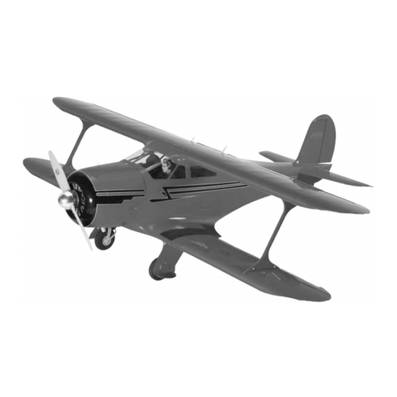
Wingspan: 72.5 in [1840mm]
Wing Area: 1525 sq in [97.6 dm
Weight: 17-19 lb [7.7-8.6 kg]
Wing Loading: 26-28 oz/sq ft
[80-90 g/dm
2
]
Length: 62.5 in [1590mm]
Radio: 6-Channel w/7 servos (minimum) or
8/9-Channel w/9 servos (w/retracts)
Engines: 1.60 cu in [25 cc] two-stroke,
1.60 cu in [25 cc] four-stroke
WARRANTY.....
from defects in both material and workmanship at the date of purchase. This warranty
does not cover any component parts damaged by use or modification. In no case shall
Top Flite's liability exceed the original cost of the purchased kit. Further, Top Flite
reserves the right to change or modify this warranty without notice.
In that Top Flite has no control over the final assembly or material used for final
assembly, no liability shall be assumed nor accepted for any damage resulting from the
use by the user of the final user-assembled product. By the act of using the user-
assembled product, the user accepts all resulting liability.
READ THROUGH THIS MANUAL BEFORE STARTING CONSTRUCTION. IT CONTAINS IMPORTANT INSTRUCTIONS AND WARNINGS CONCERNING THE ASSEMBLY AND USE OF THIS MODEL.
Top Flite Models Champaign, IL
Entire Contents © Copyright 2006
]
2
Top Flite Models guarantees this kit to be free
Telephone (217) 398-8970, Ext. 5
If the buyer is not prepared to accept the liability associated with the use of this
product, the buyer is advised to return this kit immediately in new and unused condition
to the place of purchase.
To make a warranty claim send the defective
part or item to Hobby Services at the address:
Include a letter stating your name, return shipping address, as much contact
information as possible (daytime telephone number, fax number, e-mail address), a
detailed description of the problem and a photocopy of the purchase receipt. Upon
receipt of the package the problem will be evaluated as quickly as possible.
Hobby Services
3002 N. Apollo Dr. Suite 1
Champaign IL 61822 USA
airsupport@top-flite.com
TOPZ0905 for TOPA0905 V1.0
Advertisement
Table of Contents

Related Manuals for Top Flite Models Beechcraft


Summary of Contents for Top Flite Models Beechcraft
- Page 1 Include a letter stating your name, return shipping address, as much contact In that Top Flite has no control over the final assembly or material used for final information as possible (daytime telephone number, fax number, e-mail address), a assembly, no liability shall be assumed nor accepted for any damage resulting from the detailed description of the problem and a photocopy of the purchase receipt.
-
Page 2: Table Of Contents
Fixed Tail Wheel ......17 classic airplane. Even today the Beechcraft Model 17 preserve the radio-controlled aircraft hobby are to Tail Wheel Door Installation . -
Page 3: Safety Precautions
YOURSELF & OTHERS Though the Top Flite Staggerwing is an ARF and R/C club for your first flights. If you’re not a member may not have the same level of detail as an “all-out”... -
Page 4: Decisions You Must Make
❏ Servo Horn Drill (HCAR0698) DECISIONS YOU MUST MAKE ADDITIONAL ITEMS REQUIRED ❏ Hobby Heat ™ Micro Torch (HCAR0750) ❏ AccuThrow ™ Deflection Gauge (GPMR2405) ADHESIVES & BUILDING SUPPLIES This is a partial list of items required to finish the ❏... -
Page 5: Ordering Replacement Parts
30-minute (or 45-minute) epoxy or 6-minute epoxy. When 30-minute epoxy is specified, it is Description How to purchase Replacement parts for the Top Flite Staggerwing are highly recommended that you use only 30-minute Missing pieces Contact Product Support available... -
Page 6: Kit Contents
KIT CONTENTS 1. Fuselage 2. Cowl 3. Tail Cone 4. Rudder 5. Stab with Elevators 6. Elevator Control Wire 7. Tail Wheel Hardware 8. Pilot 9. Fuel Tank 10. Pull-Pull Wire with Hardware 11. Spinner 12. Top Right Wing with Aileron 13. -
Page 7: Preparations
Note: The following steps refer to the installation of the PREPARATIONS BUILD THE WING flaps/ailerons. The bottom wing of the Staggerwing ❏ has flaps. The top wing has ailerons. If you look at the Install the Flaps/Ailerons 1. If you have not done so already, remove the location of the hinge slots of each you will see the major parts of the kit from the box and inspect for flaps are hinged off the centerline of the flap and the... -
Page 8: Install The Aileron Servos And Pushrods
screw into the holes you drilled. Apply a drop of thin Did you know… At the height of the Great CA into the holes to harden the threads. Once the glue Depression, aircraft executive Walter H. Beech has cured, install the screws into the servo cover. and airplane designer T.A. -
Page 9: Install The Flap Servos And Pushrods
through each corner of the cover. Remove the cover. over the clevis. Drill a 5/64 [2mm] hole in the outer hole 1/16" [1.6mm] drill bit. Remove the servo from the Then, install and remove a #2 x 3/8" [10mm] screw of the servo arm. -
Page 10: Install The Wing Joiners
of the servo arm. Center the servo and the flap. With a Install the Wing Joiners fine tip marker, mark the wire where it aligns with the outer hole of the servo arm. Make a 90 degree bend on the mark. Cut the wire so the wire is 3/8" [10mm] in length after the bend. -
Page 11: Attach The Wings To The Fuselage
Attach the Wings to the Fuselage ❏ ❏ 4. Using 30-minute epoxy, glue two nylon anti- rotation dowels into the holes at the root of the wing. ❏ Glue them in so 1/2" of the dowels extends from 7. Glue the remaining wing joiner into the joiner the wing. -
Page 12: Install The Struts
Install the Struts ❏ 2. Slide the two top wings together. On the bottom of the right wing you will see a threaded hole. Install a 6-32 socket head cap screw into the hole. Make sure the wings are tight against each other and then tighten the screw against the wing joiner. -
Page 13: Build The Fuselage
BUILD THE FUSELAGE Install the Stabilizers, Elevators and Rudder ❏ 1. Slide the two aluminum stab tubes into the back of the fuselage. The longer of the tubes goes into the rear-most hole. ❏ ❏ 4. Mount the strut to the bracket with a 4-40 x 1/2" 3. - Page 14 ❏ 5. Cut nine 1" x 1" [25mm x 25mm] hinges from a joiner into the hole in the leading edge of the elevator. CA hinge strip. Insert three hinges into the elevator. Once you are satisfied with the fit, apply epoxy into the If the hinges don’t remain centered, stick a pin hole in the leading edge of the left elevator and then through the middle of the hinge to hold it in position.
-
Page 15: Install The Landing Gear
5/32" [4mm] hole through each of the mounting holes INSTALL THE LANDING GEAR and into the landing gear rails. Mount the block to the landing gear rails with four #6 x 1/2" [13mm] screws The following instructions are for the installation of the and a #6 lock washer. - Page 16 ❏ ❏ ❏ ❏ 9. File a flat spot on the end of the axle. Install 11. From the 1/4" x 1/4" x 12" [6mm x 6mm x a 5mm wheel collar and set screw onto the axle. 300mm] balsa stick, cut pieces 3/4" [19mm] in length. Glue them in the wheel well 1/16"...
-
Page 17: Fixed Tail Wheel
Fixed Tail Wheel Tail Wheel Door Installation (Fixed) The following steps cover the installation of the tail wheel doors. This is optional and not required for flight performance. If you fly from a grass field that is very rough or has long grass, you might wish to omit the installation of the doors due to the amount of clearance between the doors and the ground. -
Page 18: Retractable Landing Gear
Retractable Landing Gear ❏ ❏ ❏ ❏ 5. Make a file by cutting a piece of plywood the 8. Place the door into the opening in the width of the hinge. Apply 180-grit sandpaper to the fuselage. Mark the area the hinge will be glued to the ❏... - Page 19 ❏ ❏ ❏ ❏ 3. Partially insert the landing gear into the wing. 5. Position the landing gear onto the landing Make a mark where the airline will contact the gear rails. The air cylinder will exit the side of the landing gear rail.
- Page 20 ❏ ❏ ❏ ❏ ❏ ❏ 8. Place the back strut of the landing gear into 10. Place the landing gear door over the landing 12. Measure from the tip of the door 1" [25mm] the slot molded in the fuselage. Place a flat landing gear, making sure it is centered in the wheel well.
- Page 21 ❏ ❏ 22. Remove the pointed rod from the landing ❏ ❏ ❏ ❏ 15. Measure from the bottom of the landing gear 19. Screw the pointed threaded rod into the gear. Drill a 1/8" [3mm] hole through the mark you 2"...
- Page 22 PRE-BENT WIRE PRE-BENT WIRE FOR RIGHT FOR LEFT LANDING GEAR LANDING GEAR ❏ ❏ 26. Slide a brass screw lock connector onto the wire. Then insert the pin on the connector into the outermost hole of the control horn. Secure it to the LANDING GEAR VIEWED FROM THE control arm with the nylon retainer.
-
Page 23: Retractable Tail Wheel
through all of your installation, remove the axle from the landing gear and slide two #8 flat washers onto the axle on both sides of the wheel to keep it centered in the landing gear. Be sure to use thread locker on the axle screws during the final installation. -
Page 24: Tail Wheel Door Installation
Tail Wheel Door Installation (Retractable) The following steps cover the installation of the tail wheel doors. This is optional and not required for flight performance. If you fly from a grass field that is very rough or has long grass, you might wish to omit the installation of the doors due to the amount of clearance between the doors and the ground. - Page 25 ❏ ❏ ❏ ❏ ❏ 3. Place the hinges on the line and make another 5. Make a file by cutting a piece of plywood the 9. Place the door in position on the fuselage. Mark mark at the other end of the hinge to mark the exact width of the hinge.
- Page 26 hinges, and then glue the doors into the fuselage. Note: We glued the door to the fuselage with medium CA before applying epoxy over the top of the hinge, working the epoxy into the holes in the hinge. If you have long grass that could drag against the doors, you might wish to install a small bolt and nut through the hinge and the fuselage.
-
Page 27: Install The Retract Hardware
Install the Retract Hardware ❏ 5 Glue the components of the air valve tray together. ❏ 1. Decide on a location to mount the air fill valve. Glue the plywood air valve mounting plate inside the fuselage. We mounted ours on the bottom of the fuselage. -
Page 28: Adjusting The Retractable Landing Gear
Adjusting the Retractable Landing Gear INSTALL ENGINE & THROTTLE SERVO O.S. 1.60 Two-Stroke Engine After connecting the air lines as explained in the instructions that came with the Air Control kit, fill the air tank to 100psi and try cycling the landing gear. The landing gear should cycle up and down freely. - Page 29 ❏ 5. Install the engine to the mount with four each, 8-32 x 1" [25mm] socket head cap screws, #8 lock washers and #8 flat washers. ❏ 3. Cut the tabs from the engine mount. Then, cut 1/2" [13mm] from the front of each mounting rail. (This is needed to allow room for mounting the dummy engine later in this manual).
-
Page 30: O.s. 1.60 Four-Stroke Engine
❏ 2. Install silicone fuel tubing (not supplied) onto the O.S. 1.60 Four-Stroke Engine ❏ 5. Install a brass screw lock aluminum tubes from the fuel tank. The line with the (Mounting hardware not included with kit.) connector, nylon retainer ring and a fuel clunk will feed to the fuel inlet at the needle valve 4-40 x 1/8"... -
Page 31: Install The Fuel Tank For The O.s. 1.60 Four-Stroke Engine
Install the Fuel Tank for the Install the Cowl and Dummy Engine O.S. 1.60 Four-Stroke Engine ❏ 1. Remove the muffler. This will make the installation of the cowl easier. FUEL TANK PRESSURE TAP TO MUFFLER FUEL SILICONE ❏ PIPE FUEL LINE 2. - Page 32 ❏ 8. Using medium CA, tack-glue the dummy engine ❏ ❏ 5. This step will be easier if you have a second set 6. Place the dummy engine over the engine. Then, to the cowl from inside the cowl. Re-install the cowl of hands to help you with the positioning of the cowl.
-
Page 33: Install The Radio System
❏ hide the mufflers completely inside of the engine, be 3. Remove the wires from the fuselage. On the sure you allow for an air exhaust area of at least 6 sq. threaded end of one of the wires install a 4-40 nut in. - Page 34 ❏ 6. Slide a silicone clevis retainer over the clevis ❏ ❏ you soldered to the wire. Slide the threaded end of 8. Attach each of the clevises onto the steering 10. Install the pushrod wire and clevises for the the wire into the tube and attach the solder clevis to arms of the tail wheel assembly (either the fixed tail elevator using the same technique that was used for...
- Page 35 ❏ ❏ ❏ 12. Install the servos to the receiver. Be sure to 15. Glue the sticks to the front of the former 17. Place the cockpit floor over the receiver and plug extensions into the receiver for the flaps and and even with the top of the receiver/battery battery resting on the hardwood sticks you just glued ailerons.
-
Page 36: Finishing Touches
Finishing Touches ❏ 4. Remove a small amount of covering from the wing around the wing bolts for the antennas. Glue the ❏ antennas to the wing so that the back curvature of 1. Mix 1/4 ounce [2 drams] of epoxy with microballoon the antennas fit around the bolt. -
Page 37: Get The Model Ready To Fly
GET THE MODEL READY TO FLY Set the Control Throws IMPORTANT: Staggerwing been extensively flown and tested to arrive at the Check the Control Directions throws at which it flies best. Flying your model at these throws will provide you with the greatest ❏... -
Page 38: Balance The Model Laterally
If required, tail weight should always charge your transmitter and receiver We use a Top Flite Precision Magnetic Prop Balancer may be added by cutting open the bottom of the fuse batteries the night before you go flying, and at other (TOPQ5700) in the workshop and keep a Great Planes and gluing it permanently inside. -
Page 39: Ground Check
Ground Check ENGINE SAFETY PRECAUTIONS AMA SAFETY CODE ( EXCERPTS Read and abide by the following excerpts from the If the engine is new, follow the engine Failure to follow these safety precautions may Academy of Model Aeronautics Safety Code. For the manufacturer’s instructions to break-in the result in severe injury to yourself and others. -
Page 40: Imaa Safety Code
2) I will not fly my model aircraft in the presence of Section 1.0: SAFETY STANDARD Section 5.0: EMERGENCY ENGINE SHUT OFF spectators until I become a qualified flier, unless 1.1 Adherence to Code: The purpose of this Safety (Kill Switch) assisted by an experienced helper. -
Page 41: Check List
considered. This should be considered a minimum weight greater than 36 pounds. With the same CHECK LIST for smaller aircraft and higher torque servos are engine, an aircraft weighing less than 15 pounds strongly encouraged for larger aircraft. The use of would likely be overpowered. -
Page 42: Flying
❏ 9. Reinforce holes for wood screws with thin CA FLYING Takeoff where appropriate (servo mounting screws, The Staggerwing is a great-flying model that flies cowl mounting screws, etc.). Before you get ready to take off, see how the model smoothly and predictably. -
Page 43: Flight
turn onto the crosswind leg. Make your final turn Flight ITEMS AVAILABLE FOR YOUR toward the runway (into the wind) keeping the nose STAGGERWING down to maintain airspeed and control. Level the For reassurance and to keep an eye on other traffic, attitude when the model reaches the runway it is a good idea to have an assistant on the flight line Futaba... - Page 44 O.S. ® 1.60 FX Ringed Engines O.S. ® FT-160 Twin Cylinder 4-Stroke The 1.60 FX features dual ball bearings for durability and smooth operation, plus a low crankcase profile that allows for a proportionally taller, semi-squared head - a design refinement that increases cooling fin area and improves heat dispersion.
Need help?
Do you have a question about the Beechcraft and is the answer not in the manual?
Questions and answers