Table of Contents
Advertisement
Quick Links
DVD RECORDER
DVR-230-S
DVR-230-AV
THIS MANUAL IS APPLICABLE TO THE FOLLOWING MODEL(S) AND TYPE(S).
Model
Type
DVR-230-S
WYXV
DVR-230-S
WVXV
DVR-230-S
WYXV/RE
DVR-230-AV
WYXV
DVR-230-AV
WVXV
÷
When servicing this model, some service procedures may reset the customer settings
to the factory default settings. Make sure to explain this to the customer.
Refer to the chapter 8 of the Operating Instructions for more details about the customer
settings.
For details, refer to "Important Check Points for Good Servicing".
PIONEER CORPORATION
PIONEER ELECTRONICS (USA) INC. P.O. Box 1760, Long Beach, CA 90801-1760, U.S.A.
PIONEER EUROPE NV Haven 1087, Keetberglaan 1, 9120 Melsele, Belgium
PIONEER ELECTRONICS ASIACENTRE PTE. LTD. 253 Alexandra Road, #04-01, Singapore 159936
PIONEER CORPORATION 2005
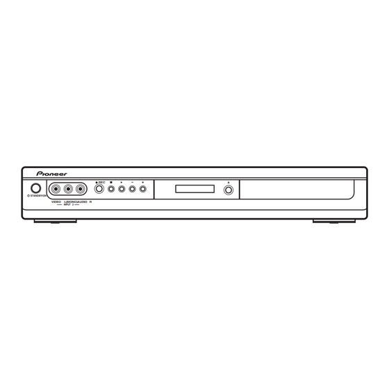
STANDBY/ON
VIDEO
L(MONO)AUDIO R
INPUT 2
Power Requirement
AC220-240V
AC220-240V
AC220-240V
AC220-240V
AC220-240V
4-1, Meguro 1-chome, Meguro-ku, Tokyo 153-8654, Japan
REC
DVR-230-S
Region No.
2
2
5
2
2
ORDER NO.
RRV3245
Serial No.
Please confirm 3rd & 4th
alphabetical letters.
&&DL######$$
&&DL######$$
&&DL######$$
&&DL######$$
&&DL######$$
T-ZZV AUG. 2005 printed in Japan
Advertisement
Table of Contents

Related Manuals for Pioneer DVR-230-AV


Summary of Contents for Pioneer DVR-230-AV
-
Page 1: Dvd Recorder
PIONEER CORPORATION 4-1, Meguro 1-chome, Meguro-ku, Tokyo 153-8654, Japan PIONEER ELECTRONICS (USA) INC. P.O. Box 1760, Long Beach, CA 90801-1760, U.S.A. PIONEER EUROPE NV Haven 1087, Keetberglaan 1, 9120 Melsele, Belgium PIONEER ELECTRONICS ASIACENTRE PTE. LTD. 253 Alexandra Road, #04-01, Singapore 159936 PIONEER CORPORATION 2005 T-ZZV AUG. -
Page 2: Safety Information
SAFETY INFORMATION LABEL CHECK LASER DIODE CHARACTERISTICS IMPORTANT MAXIMUM OUTPUT POWER: 100 mW THIS PIONEER APPARATUS CONTAINS WAVELENGTH: 654 - 662 nm LASER OF CLASS 1. SERVICING OPERATION OF THE APPARATUS LASER DIODE CHARACTERISTICS SHOULD BE DONE BY A SPECIALLY MAXIMUM OUTPUT POWER: 5 mW INSTRUCTED PERSON. - Page 3 To protect products from damages or failures during transit, the shipping mode should be set or the shipping screws should be installed before shipment. Please be sure to follow this method especially if it is specified in this manual. DVR-230-S...
-
Page 4: Table Of Contents
7.1.3 CPRM ID NUMBER AND DATA SETTING.................... 62 7.1.4 SERVICE MODE........................... 65 7.1.5 AGING MODE............................69 7.1.6 DISASSEMBLY ............................. 70 7.2 IC ................................75 7.3 OUTLINE OF THE PRODUCT......................... 84 7.4 DISC/CONTENT FORMAT ........................85 8. PANEL FACILITIES ............................86 DVR-230-S... -
Page 5: Specifications
During audio input ......2V rms (Input impedance: more than 22 kΩ) Jacks ....AV connector 2, RCA jacks DVR-230-S... -
Page 6: Supplied Accessories
Remote control ........1 (DVR-230-S types only) - Page 7 (VXX2983 : WYXV type) • RF antenna cable(PAL) ×1 • Power cable ×1 (VXX2982 : WVXV type) (VDE1075) (ADG7090 : WYXV,WYXV/RE type) DVR-230-S types only STANDBY/ON DISPLAY (ADG7103 : WVXV type) AUDIO SUBTITLE ANGLE • Audio / Video cable(1.5m) ×1...
-
Page 8: Exploded Views And Parts List
For the applying amount of lubricants or glue, follow the instructions in this manual. (In the case of no amount instructions, apply as you think it appropriate.) 2.1 PACKING SECTION DVR-230-S only for WYXV type for WVXV type for WYXV/RE type... - Page 9 Packing Case See Contrast table (2) Mirror Sheet VHL1089 WEEE Label See Contrast table (2) (2) CONTRAST TABLE DVR-230-S/WYXV, WVXV, WYXV/RE, DVR-230-AV/WYXV and WVXV are constructed the same except for the following : DVR-230-S DVR-230-S DVR-230-S DVR-230-AV DVR-230-AV Mark No.
-
Page 10: Exterior Section
2.2 EXTERIOR SECTION Refer to "2.3 FRONT PANEL SECTION". DVR-230-S... - Page 11 NSP 18 Cover VNE2383 Tray Panel VNK5766 NSP 20 HASB Assy VNP2018 (2) CONTRAST TABLE DVR-230-S/WYXV, WVXV, WYXV/RE, DVR-230-AV/WYXV and WVXV are constructed the same except for the following : DVR-230-S DVR-230-S DVR-230-S DVR-230-AV DVR-230-AV Mark No. Symbol and Description...
-
Page 12: Front Panel Section
2.3 FRONT PANEL SECTION FLDB CN202 SCRB CN203 7 (1/2) 7 (2/2) DVR-230-S... - Page 13 VNK5769 Front Panel See Contrast table (2) Screw BPZ30P080FTC PW Key VNK5924 (2) CONTRAST TABLE DVR-230-S/WYXV, WVXV, WYXV/RE, DVR-230-AV/WYXV and WVXV are constructed the same except for the following : DVR-230-S DVR-230-S DVR-230-S DVR-230-AV DVR-230-AV Mark No. Symbol and Description...
-
Page 14: Block Diagram And Schematic Diagram
(40P) IC202 SDRAM 16Mbit CN101 IC203 FLASH (45P) IC201 UPD63641GM SPDL MAIN ASSY MOTOR Pickup DRIVE Flash 32Mbit IC1102 PB DVD/CD RF IC IC101 PICKUP UPC3340GC CN501 ASSY (12P) Driver LOADING MOTOR DRIVE ASSY(R9R) CN502 IC501 STEPPIONG BD7997FS MOTOR DVR-230-S... -
Page 15: Jacb Assy
V/Y Out C OUT AV2_VY L Out IC3201 AV1_L PCM1742KE AV2_L Audio L OUT D/A Conv. IC3202-1/2 UPC4570G2 SPDIF Tuner U-com SCRB ASSY CN204 FLKY ASSY (13P) (13P) UP(+) PLAY CN205 FLDB ASSY CN202 CN201 STOP OPEN DOWN(-) (11P) DVR-230-S... -
Page 16: Overall Wiring Diagram
÷ The > mark found on some component parts indicates the importance of the safety factor of the part. Therefore, when replacing, be sure to use parts of identical designation. FRJB ASSY ÷ : The power supply is shown with the marked box. (VWV2141) DVR-230-S... - Page 17 JA402 R_OUT VKB1150- GNDA REAR OUTPUT L_OUT VOUT2 COUT2 JA403 YOUT2 AMUTE REAR OUTPUT JA201 RKN1004- SR IN CN601 DVR-230-AV VKN2016- CN701 types Only VKN2016- 1/3 - V+5R8SW SCRB ASSY(VWV2140) STACHG XRST1 FLDB ASSY(VWV2142) FLKY ASSY (VWV2144) VAW1087- V201 DVR-230-S...
-
Page 18: Jacb And Flky Assys
C907 (SIF) 56p/50 TESTEN SCOR 3p/50 (SIF) R928 V+5R8SW VREF1 C926 R905 XOUT 0.01/50 DACML R921 R922 DCO1 DACMR 3.3k 3.3k DCO0 VREF2 C915 R907 ADSEL 3p/50 STBYQ CN601 15 16 20 21 R923 R924 R925 R926 GND GND DVR-230-S... - Page 19 SR IN R212 R213 TP204 TP203 V+5R8SW R436 C404 C405 R401 Q705 R407 C403 R405 1/50 JACB ASSY (VWV2143 : DVR-230-S) JA401 AUDIO OUTPUT VKB1159- (VWV2147 : DVR-230-AV) DIGITAL JA402 R444 1.5k(2125) (Cr) VKB1150- C418 470/6.3 R414 75F(2125) R445 1.5k(2125)
-
Page 20: Scrb(1/3), Frjb And Fldb Assys
SEL_IR 2-C6 R169 R213 IC102 2-C6 BD4846G-TRB P_CONT HST_TO_M V+5V V+5R8E DAT_TO_M V+5VI DAM_TO_T R170 D107 R171 1SS355-TRB ASCK Q106 HSM_TO_T XRST1 XRST1 1-C3 R179 V+5M Q108 D106 R172 1SR154-400-TRB Q107 C144 1u/10 R184 C145 TEXTV 1-A2 3-A3 TEXTVIN DVR-230-S... - Page 21 S501 C522 Power ON VSG1024- -T R223 1-C3 KEY1 KEY1 R222 V+5F FRONT INPUT R224 D504 L501 VTL1087- -T JA502 VKB1206- R225 R532 R228 D503 R533 R522 VKN2015- VKN2015- CN203 CN501 R534 R524 R291 R292 D505 R293 D503D505:UMZ6R8N-TLB R294 DVR-230-S...
-
Page 22: Scrb Assy (2/3)
V+5R8E V+5VO VNE1948- R1208 Q305 Q304 R1209 R1210 KN302 R1211 VNF1084- -T R1212 KN303 Q312 R336 R1213 XP_SAVE KN304 R1214 VNF1084- -T R1215 KN306 R1216 V+31E R1217 R326 V+31V R1218 Q306 UMF23N-TLB R308 R1219 R1220 ***(3216) TUON Q306 UMF23N-TLB DVR-230-S... - Page 23 : COMPONENT VIDEO SIGNAL ROUTE (Cr ch) (Cb) : COMPONENT VIDEO SIGNAL ROUTE (Cb ch) (Yp) : COMPONENT VIDEO SIGNAL ROUTE (Yp ch) : AUDIO SIGNAL ROUTE (L ch) : AUDIO SIGNAL ROUTE (Digital ch) (SIF) : AUDIO SIGNAL ROUTE (SIF ch) DVR-230-S...
-
Page 24: Scrb Assy (3/3)
: COMPONENT VIDEO SIGNAL ROUTE (G ch) : COMPONENT VIDEO SIGNAL ROUTE (B ch) (R/C) : COMPONENT VIDEO SIGNAL ROUTE (R/C ch) Q817 : AUDIO SIGNAL ROUTE (L ch) : AUDIO SIGNAL ROUTE (Digital ch) (TU) : AUDIO SIGNAL ROUTE (TU ch) DVR-230-S... - Page 25 C B2 E2 B C2 SN74AHC2G53 V+5V UMH1N(R=22kΩ) UMD2N(R=22kΩ) A(5) C B2 E2 XTHROU XTHROU 1-B3 D830 D831 B C2 IC806 V+5V UMF21N(R=10kΩ) UMF23N D829 R846 AVLIN 1SS355-TRB 1-A3 SN74AHC2G53HDCT-TRB 2.2M C873 220p/50 Q811 R851 1-B3 AVLOUT 100k 1-A3 XAVLTH DVR-230-S...
-
Page 26: Main Assy (1/2)
V+3D V+3V V_VENC 1R5V PVDD RS-232C L1008 DTL1106- -T L1007 DTL1106- -T JTMRST V+3D V+5A JTDI GNDD GNDD CN1402 JTDO R1423 JTMS V+3D C1451 JTCL R1424 IC1451 R1453 V+5D EDINT GNDD R1454 R1425 232RST XRESET 2-D5 GNDD GNDD GNDD DVR-230-S... - Page 27 33(S) DCAS TCAS TADRS12 DRAS TRAS TBA0 TADRS11 TBA1 TADRS9 TADRS10 TADRS8 56*4 GNDD R1298 TADRS0 TADRS7 R1288 33(S) DCLKO TCLKO TADRS1 TADRS6 DCLKNO TCLKNO TADRS2 TADRS5 C1230 R1289 R1299 TADRS3 TADRS4 33(S) C1228 1000p 256Mbit DDR SDRAM GNDD DVR-230-S...
-
Page 28: Main Assy (2/2)
R3107 BYPAS DGND R3112 ADATAI TEST DOUT GNDD BCKI LRCK R3104 LRCKI R3106 for around upper left screw for around upper right screw GNDD GNDD GNDD GNDD for around lower left screw for around lower right screw GNDD GNDD DVR-230-S... - Page 29 : COMPONENT VIDEO SIGNAL ROUTE (Yp ch) IC3701 TC7WH34FU-TRB : AUDIO SIGNAL ROUTE (L ch) R3703 HS_T_TO_M SS_T_TO_M R3704 : AUDIO SIGNAL ROUTE (Digital ch) (AD) : AUDIO DATA SIGNAL ROUTE C3703 R3706 GNDD 5V = 3V Converter R3722 R3723 R3724 GNDD DVR-230-S...
-
Page 30: Power Supply Unit
3.9 POWER SUPPLY UNIT DVR-230-S... -
Page 31: Waveforms
V: 0.5V/div. H: 10µsec/div. (AV2 INPUT RGB Setting / Stand-by) V: 0.5V/div. H: 10µsec/div. CN301-19pin (CR_OUT) CN603-17pin (YOUT) CN603-5pin (COUT2) IC100-46pin (G) V: 0.5V/div. H: 10µsec/div. V: 0.5V/div. H: 10µsec/div. V: 0.5V/div. H: 10µsec/div. (RGB OUTPUT Setting) V: 0.5V/div. H: 10µsec/div. DVR-230-S... - Page 32 V: 0.5V/div. H: 10µsec/div. V: 0.5V/div. H: 10µsec/div. IC100-22pin (AV2_V/Y OUT) JA802-11pin(Gout) (VIDEO OUT) (RGB OUTPUT Setting) V: 0.5V/div. H: 10µsec/div. V: 0.5V/div. H: 10µsec/div. IC100-16pin (AV1_V/YIN) JA802-15pin (R/Cout) (VIDEO IN) (RGB OUTPUT Setting) V: 0.5V/div. H: 10µsec/div. V: 0.5V/div. H: 10µsec/div. DVR-230-S...
- Page 33 V: 2V/div. H: 200µsec/div. V: 0.5V/div. H: 10µsec/div. CN2301 - pin 40 (SPDIF) CN2301 - pin 19 (Cr OUT) (State : 1kHz 2Vrms A1 disc 2-1) (State : 75% Color-bar A1 disc 2-20) V: 0.5V/div. H: 500nsec/div. V: 0.5V/div. H: 10µsec/div. DVR-230-S...
- Page 34 DVR-230-S...
-
Page 35: Pcb Connection Diagram
Symbol In PCB Symbol In Schematic Part Name Diagrams Diagrams C E B Capacitor Connector Transistor B C E SIDE A Transistor with resistor B C E Field effect SIDE B P.C.Board Chip Part transistor Resistor array 3-terminal regulator DVR-230-S... -
Page 36: Jacb Assy
SIDE A JACB ASSY JA403 JA401 JA201 JA402 W129 JACB ASSY C502 VWV2143 VWV2147 CMKD-P3X C933 C501 W110 W113 V+5R8SW W123 V+5R8SW C934 W121 W109 CN501 SEL_IR W108 AMUTE W101 W107 V+5R8SW V+5R8SW W106 CN701 (VNP2018-B) CN501 CN701 CN603 CN601 DVR-230-S... - Page 37 R927 Q905 Q905 Q903 Q903 V+5R8SW C930 L903 C931 C503 Q906 Q906 R907 CMKD-P3X R909 SEL_IR AMUTE IC901 V+5R8SW V+5R8SW CN501 C906 C908 C917 R1035 C905 Q904 Q904 R1030 R1033 R1028 R1032 R1023 R1024 R1031 R1026 R1034 (VNP2018-B) CN701 DVR-230-S...
-
Page 38: Flky Assy
4.2 FLKY ASSY SIDE A SIDE A FLKY ASSY CN202 IC202 (VNP2018-B) DVR-230-S... - Page 39 SIDE B SIDE B FLKY ASSY C234 11.V+5F 10.KEY2 9.GND 8.IR 7.GND 6.FL-24V 5.FLDATA 4.FLDC+ 3.FLSTB 2.FLDC- 1.FLCLK C241 R241 C216 FL-24V R206 R211 R207 R208 R209 V+5FL C209 C211 IC201 C210 (VNP2018-B) DVR-230-S...
-
Page 40: Scrb Assy
1.V+5F C705 Q703 R311 IC701 R332 Q703 Q312 R701 Q307 R335 Q307 R336 Q701 C503 Q701 CN301 CONTACT SIDE Q804 CONTACT SIDE C505 V+5R8E IC801 CN302 R630 Q816 Q817 CN602 Q806 IC301 CN301 CN603 CN2301 CN501 Q314 Q109 Q308 DVR-230-S... - Page 41 C351 C353 D819 V+5R8SW R815 R802 R804 C345 Q806 R805 C802 R810 C313 R806 R811 D820 IC301 C804 C801 C312 R812 V+3R7SW C876 R807 C803 D832 V+12R1E V+12R1 Q314 V+31E V+5R8E V+12R1SW R632 Q308 CN101 CN303 (VNP2017-B) CN303 CN201 DVR-230-S...
- Page 42 R808 Q801 C350 D807 Q310 R315 D804 Q311 Q311 Q818 Q818 D805 C311 D828 Q309 Q309 C349 C881 D826 D822 D825 C879 CN303 D301 C308 C309 Q110 D824 C305 C152 C301 C303 R1104 C304 Q201 D111 Q202 Q203 CN303 DVR-230-S...
- Page 43 R104 R140 2.FLDATA R174 R141 1.V+5F R138 R102 R139 R1101 R162 D501 R142 R161 CN102 C106 R1115 R101 R511 R166 C504 CN302 R1118 R512 C530 V+12R1JSW Q503 V+5R8SW Q505 D502 R514 C310 V+1R5 R513 CMKD-P3X CN301 C311 (VNP2017-B) CN301 DVR-230-S...
-
Page 44: Fldb And Frjb Assys
4.FLSTB 8.GND 2.FLDATA 5.GND 9.IR 10.V+12R1E 12.FLPON 3.KEY2 6.FLCLK 11.GND 13.GND (VNP2017-B) CN202 CN205 CN201 CN204 FRJB ASSY 1.GND 5.2L FRJB ASSY 2.GND 6.GND 8.V+5F 3.2R 9.KEY1 VWV2141 4.GND 7.2V CN501 JA502 CMKD-P3X S501 Power ON (VNP2017-B) CN501 CN203 DVR-230-S... - Page 45 (VNP2017-B) CN205 CN202 FRJB ASSY 8.V+5F VWV2141 1.GND 5.2L CN501 9.KEY1 6.GND 2.GND 7.2V 3.2R R534 4.GND R533 FRJB ASSY L501 R523 R517 C521 C519 C522 R521 R532 R526 R531 C516 C515 R522 D504 C520 D505 CMKD-P3X CN501 (VNP2017-B) DVR-230-S...
-
Page 46: Main Assy
4.5 MAIN ASSY SIDE A MAIN ASSY DVR-230-S... - Page 47 SIDE A CN301 CN2301 to DRIVE ASSY (VNP1999-A) DVR-230-S...
- Page 48 SIDE B MAIN ASSY DVR-230-S...
- Page 49 SIDE B (VNP1999-A) DVR-230-S...
-
Page 50: Power Supply Unit
4.6 POWER SUPPLY UNIT SIDE A SIDE A POWER SUPPLY UNIT AC IN DRIVE ASSY CN401 CN303 DVR-230-S... - Page 51 SIDE B SIDE B POWER SUPPLY UNIT DVR-230-S...
-
Page 52: Pcb Parts List
CKSRYF104ZJ16 JA201 (JACK) Not used RKN1004 Mark No. Description Part No. Mark No. Description Part No. C907, C915 CCSRCJ3R0C50 JACB ASSY (DVR-230-S types) C937, C939 CEAT100M50 C934-C936, C940, C941 CEAT101M16 SEMICONDUCTORS C420, C421, C423 CEAT102M6R3 IC901 MSP3417G C403 CEAT1R0M50 Q903, Q904... - Page 53 C302-C304, C310, C317, C38 CKSRYF105Z10 Q603 UMF21N C43, C5 CKSRYF105Z10 Q306, Q311 UMF23N RESISTORS Q804 UMH1N D106 1SR154-400 R701, R703 RN1/16SE1002D D101, D103, D107, D501, D502 1SS355 R707, R708 RN1/16SE8201D D801, D820, D829 1SS355 R31, R313, R41, R55, R57 RS1/10S0R0J DVR-230-S...
- Page 54 Q203 2SC4081 C1901, C1912, C2205, C2215 CCSRCH180J50 > Q201 2SC5712 C1803 CCSRCH221J50 D203 1SS355 C1802, C3204 CCSRCH331J50 D204, D205 RF101L2S C3501 CCSRCH470J50 C2231, C2233 CCSRCH5R0C50 D202 UDZS15(B) D206 UDZS2R4(B) C2201, C2211 CCSRCH680J50 D207 UDZS9R1(B) C3208, C3210 CCSRCH681J50 C1708 CEVW100M16 DVR-230-S...
-
Page 55: Adjustment
RN1/16SE1502D R3209, R3224 RN1/16SE8201D R1002, R2200, R4522, R4532 RS1/10S0R0J R4591-R4593 RS1/10S0R0J R1302, R1303, R1312, R1313, R3110 RS1/16S1001F R2213, R2214 RS1/16S1601F R2502, R2505, R2508, R2511, R2514 RS1/16S2000F R1301, R2201, R2202 RS1/16S4700F R1052 RS1/16S6200F R3505 RS1/16S75R0F R1054 RS1/16S9100F Other Resistors RS1/16S###J DVR-230-S... -
Page 56: General Information
( MAIN, SCRB and DRIVE ASSY) #2, Simple Err Rate Mesurement • To check the status of DRIVE ASSY #3, LD degration Judge in ATA/ATAPI Debug • To check the DRIVE ASSY and DISC when the symptom 7.1.5 AGING MODE does not occur, etc. DVR-230-S... - Page 57 ATA/ ATAPI DEBUG for LD degration Judge. Load a Select recordable the input AGING MODE REP.B DISC function Put DL DISC(*1) FIRMWARE DOWNLOAD REC(*2) POWER(*2) On tray *1 DL DISC: Download DISC *2 These keys are on the Front panel. DVR-230-S...
-
Page 58: Model Type Setting
Model SYSCON : RELEASE_31 Name " DVR-230/WY ". : 3.04Z.110 TUFLCON : 870.000 Flash DRIVE : DVD-RW DVR-R09R 1.54 DKT0000100JP DEVICE : EMMA2RL REGION : ∗ ∗ ∗ ∗ ∗ ∗ ∗ ∗ ∗ FLASH : 32M DVR-230-S... -
Page 59: Firmware Downloading Method
4 Press " ESC " button, then press " DISP " button on the remote control unit for servicing. 5 Confirm a firmware release version. 6 Press " ESC " button on the remote control unit for servicing in order to exit the test mode. DVR-230-S... - Page 60 • In a case where downloading was incorrectly terminated while "DL-3" was displayed on the FL display The program for the tuner microcomputer will not function correctly. If the program cannot be downloaded from the disc or through serial communication, replace the TUFLCON microcomputer (IC101 : SCRB ASSY). DVR-230-S...
- Page 61 5 minutes for updating the firmware.) 9 After finishing the update, push "OK" button, and then finish the Image Updater by pushing "Stop" button. 0 Unplug the power cable first, and then the FFC cable. (Be sure to keep this order.) DVR-230-S...
-
Page 62: Cprm Id Number And Data Setting
• Input the ID number while the unit is in Stop mode. • Uses only the remote control for servicing except open/close key on the player. • After the data are read from the ID data disc (GGV1238), the disc will automatically be unloaded. DVR-230-S... - Page 63 (The FL display indicates "INS") In this condition, place the ID data disc on the tray and close the tray using the OPEN/CLOSE key "0" on the player. [Recorder's ID Data Setting] <CLEAR> Exit Input The ID Data Disc ! DVR-230-S...
- Page 64 ID Number ? [ 0 0 0 0 0 0 0 0 1] Compare > 0 0 0 0 0 0 0 0 1 OK ? <PLAY> Enter <STOP> Memory Clear <STEREO> ID Data Setting Mode Input ID Number ! DVR-230-S...
-
Page 65: Service Mode
While the GUI screen is not displayed, press the ESC then DISP keys. How to enter and change subscreens of the first screen: While the first screen is displayed, press the DIG/ANA key repeatedly until your desired subscreen is displayed. The subscreens change cyclically. [How to quit] Press the ESC key. DVR-230-S... - Page 66 3 Version No. of the tuner microcomputer, Mask or Flash Result of the combination ckeck with system u-com 4 Information on the built-in drive (Model name, version No., model type, serial No.) 5 Description of MAIN LSI 6 Region No. 7 CPRM information (CPRM key No.) DVR-230-S...
- Page 67 Table 1: Thresholds when determining OK or Error Finalized or not Recording Disc type Reference value Display finalized mode − − 8.0×10 OK/Error DVD-VIDEO Video mode Finalized 1.0×10 OK/Error DVD-R Not finalized 1.0×10 OK/Error Video mode Finalized 1.0×10 OK/Error DVD-RW Not finalized 1.0×10 OK/Error DVR-230-S...
- Page 68 No disc inserted in the disc tray Temperature (approx. 25°C) inside the Writer during adjustment No disc inserted in the disc tray If the results of degradation of the LDs for CDs and DVDs are both NG, replace the drive. DVR-230-S...
-
Page 69: Aging Mode
OSD. Note: Recording time depends on the recording rate set. For example, if the recording rate is XP, only up to 60 titles can be registered. Check the setting for recording rate before performing aging. DVR-230-S... -
Page 70: Disassembly
20 mm, you cannot catch the projection. Emergency disc ejection rod (GGF1529) Emergency disc ejection rod (GGF1529) Slit of chassis Slit of drive about Projection about 15mm (slide) Slit Cam R9 Bottom view Bottom view DVR-230-S... - Page 71 Main IC (IC1001) on the MAIN Assy will be heated to arround 80 degrees, celsius. JACB Assy Be careful when works. Flexible cable for service (GGD1436) SCRB Assy CN301 CN2301 SCRB Assy MAIN Assy CN2301 CN301 IC1001 MAIN Assy Diagnosis DVR-230-S...
- Page 72 Connect the flexible cable for service. Arrange the unit as shown in the photo below. JACB Assy Flexible cable for Bottom view service (GGD1436) SCRB Assy Remove the front panel section. CN301 CN2301 MAIN Assy Diagnosis Front panel section DVR-230-S...
- Page 73 Remove the two screws. Remove the one screw. Tape Remove the four screws. Remove the DRIVE Assy R9R. DRIVE Assy R9R DRIVE Assy R9R Bottom view Remove the two screws. Remove the writer stay. Writer stay DRIVE Assy R9R Front side DVR-230-S...
- Page 74 Front bezel Clean the pickup lens. Before shipment, be sure to clean the pickup lens, Remove the one screw. using the following cleaning materials: Remove the top cover. Cleaning liquid : GEM1004 Cleaning paper : GED-008 Pickup lens Top cover DVR-230-S...
- Page 75 Input selection of video selector PE3/AN15 INSEL1 INSEL2 Input selection of video selector Input selection of video selector INSEL3 YCSEL CVBS or Y/C selection of video selector STBYVS Standby mode selection of video selector − VSS4 − VDD4 VDD4 DVR-230-S...
- Page 76 P27/INT5/T1IN/TOCLP/TOHCP BLANKIN DVD indicator P30/PWM4 LEDDVD P31/PWM5 LEDHDD HDD indicator Transmission for RS232-C terminal P32/UTX1 TXD1 Reception for RS232-C terminal P33/URX1 RXD1 Reservation P34/UTX2 TXD2 Reservation P35/URX2 RXD2 SYS → Tuner HS_TTOM Handshaking of sys con − VDDODA VDDODA DVR-230-S...
- Page 77 Nch O/D PC4/AN10 PC3/AN11 PC2/AN9 PC1/AN8 PC0/OCSYNC Tuner → Sys Communication data line of sys con PA0/SO7 SD_TTOM Sys → Tuner Communication data line of sys con PA1/SI7/SB7 SD_MTOT Sys → Tuner Communication clock of sys con 100 PA2/SCK7 SCK_MTOT DVR-230-S...
- Page 78 HA118326APFR (SCRB ASSY : IC100) • IC for DVD REC Block Diagram DVR-230-S...
- Page 79 1.4Vpp (1.977Vpp) Sync tip = 1.4V 75Ω Driver Vcc SCART G input 0.7Vpp (0.785Vpp) Sync tip = 1.8V SCART R to C input 0.7Vpp (0.99Vpp) Sync tip = 1.8V(Bias = 2.3V) SCART B input 0.7Vpp (0.785Vpp) Sync tip = 1.8V DVR-230-S...
- Page 80 -20dBV(3dBV) 4.5V <PAL> Audio AV1 RCA out (L) -20dBV(3dBV) 4.5V RF-Converter Audio output -14dBV(6dBV) 4.5V Audio AGC detector 0.5V VTR V or Y & Separation Y3 input VTR : 2Vpp (2.825Vpp) Y3 : 1Vpp (1.413Vpp) Sync tip = 1.8V DVR-230-S...
- Page 81 BAOOBCOWFP (SCRB ASSY : IC801) Regulator 1 pin : CTL 2 pin : Vcc 3 pin : GND 4 pin : OUT 5 pin : C DVR-230-S...
- Page 82 Input is only YC 2ch, or V. 3D Y/C separation, 3D noise filter detection Clock Y/C separation Conversion Video signal Video signal Video siganl Color Video signal processing processing input output Input block block demodulation output block block Clock generator I2C register DVR-230-S...
- Page 83 Decimation V REF1 Filter Reference with Mode/ V REF 2 High-Pass Filter Format FMT0 Control FMT1 MODE0 Delta-Sigma V IN R Modulator MODE1 BYPAS TEST Clock and Timing Control PDWN Power Supply SCKI V CC AGND DGND V DD DVR-230-S...
-
Page 84: Outline Of The Product
The storing area of a program code and setting information The backup data of Tuner information and user setting • CPU SDRAM (IC1201, IC1202 MAIN ASSY) The execution area and working area of a program An overall memory for system assuring 32 bit width DVR-230-S... -
Page 85: Disc/Content Format
• DVD-RW Ver. 1.1, Ver. 1.1 / 2x and Ver. 1.2 / 4x • DVD-R Ver. 2.0, Ver. 2.0 / 4x / 8x and Ver. 2.1 / 16x Recording formats: • DVD-R: DVD-Video format (Video mode) • DVD-RW: Video Recording (VR) format and DVD- Video format (Video mode) DVR-230-S... -
Page 86: Panel Facilities
DVD-RW. ì Lights during recording; blinks when recording is 11 2 3 paused. Shows the remote control mode (if nothing is displayed, the remote control mode is 1). OVER Lights when the analog audio input level is too high. DVR-230-S... -
Page 87: Rear Panel
(composite) ANTENNA IN/OUT video jack, and stereo analog audio jacks. Connect your TV antenna to the ANTENNA IN jack. The signal is passed through to the ANTENNA OUT jack forconnection to your TV. DVR-230-S... -
Page 88: Remote Control
(or an external input). Press repeatedly to skip progressively forward Number buttons, CLEAR through the audio or video playing. Use the number buttons for track/chapter/title selection; channel selection, and so on. Use CLEAR to clear an entry and start again. DVR-230-S... - Page 89 DVR-230-S...
- Page 90 GGF1529 diagnosis of MAIN Assy Before shipping out the product, be sure to clean the following positions by using the prescribed cleaning tools: Position to be cleaned Cleaning tools Pickup lenses Cleaning liquid : GEM1004 Cleaning paper : GED-008 DVR-230-S...
Need help?
Do you have a question about the DVR-230-AV and is the answer not in the manual?
Questions and answers