Table of Contents
Advertisement
Quick Links
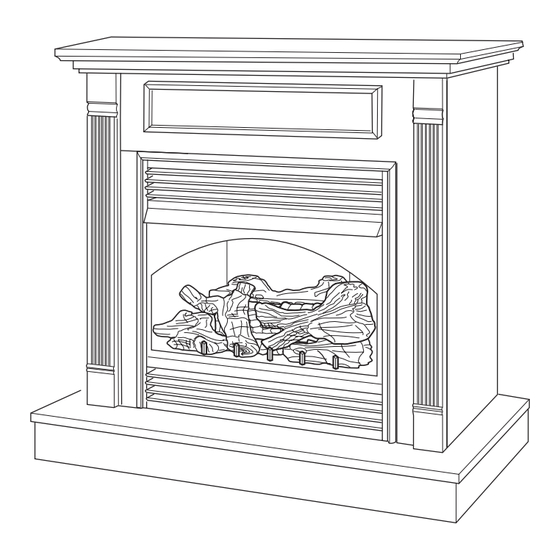
UNVENTED (VENT-FREE) GAS FIREPLACE
OWNER'S OPERATION AND INSTALLATION MANUAL
Shown with optional cabinet mantel with hearth base and trim accessories.
REMOTE-READY FIREPLACE SYSTEM
WARNING: If the information in this manual is not
followed exactly, a fire or explosion may result causing
property damage, personal injury, or loss of life.
— Do not store or use gasoline or other flammable
vapors and liquids in the vicinity of this or any other
appliance.
— WHAT TO DO IF YOU SMELL GAS
• Do not try to light any appliance.
• Do not touch any electrical switch; do not use any
phone in your building.
• Immediately call your gas supplier from a neighbor's
phone. Follow the gas supplier's instructions.
• If you cannot reach your gas supplier, call the fire
department.
— Installation and service must be performed by a quali-
fied installer, service agency, or the gas supplier.
INSTALLER: Leave this manual with the appliance.
CONSUMER: Retain this manual for future reference.
For more information, visit www.fmiproducts.com
VSGF33PRC AND VSGF33NRC
PFS
®
US
Advertisement
Table of Contents

Related Manuals for FMI VSGF33PRC


Summary of Contents for FMI VSGF33PRC
- Page 1 OWNER’S OPERATION AND INSTALLATION MANUAL ® Shown with optional cabinet mantel with hearth base and trim accessories. VSGF33PRC AND VSGF33NRC REMOTE-READY FIREPLACE SYSTEM WARNING: If the information in this manual is not followed exactly, a fire or explosion may result causing property damage, personal injury, or loss of life.
-
Page 2: Table Of Contents
TABLE OF CONTENTS Safety ..............2 Wiring Diagram ..........23 Product Identification ........... 4 Troubleshooting ..........24 Local Codes............5 Parts ..............28 Unpacking............5 Replacement Parts ..........32 Product Features ..........5 Specifications ............ 32 Air For Combustion and Ventilation ..... 6 Service Hints ............. - Page 3 SAFETY Continued Do not place clothing or other DANGER: Carbon monoxide flammable material on or near poisoning may lead to death! the appliance. Never place any objects on the heater. Carbon Monoxide Poisoning: Early signs of carbon monoxide poisoning resemble the flu, with headaches, dizziness, or nausea.
-
Page 4: Product Identification
SAFETY Continued 3. If you smell gas Depletion Sensing (ODS) safety shutoff system. The ODS shuts down the fire- • shut off gas supply place if enough fresh air is not available. • do not try to light any appliance See Air for Combustion and Ventilation, •... -
Page 5: Local Codes
LOCAL CODES Install and use fireplace with care. Follow all State of Massachusetts: The installation local codes. In the absence of local codes, must be made by a licensed plumber or use the latest edition of The National Fuel gas fitter in the Commonwealth of Mas- Gas Code ANSI Z223.1/NFPA 54*. -
Page 6: Air For Combustion And Ventilation
AIR FOR COMBUSTION AND VENTILATION Unusually tight construction is defined as WARNING: This heater shall construction where: not be installed in a room or a. walls and ceilings exposed to the out- side atmosphere have a continuous space unless the required vol- water vapor retarder with a rating of one ume of indoor combustion air perm (6 x 10... - Page 7 AIR FOR COMBUSTION AND VENTILATION Continued Example: Space size 20 ft. (length) x 16 ft. If the actual Btu/Hr used is less than the maxi- (width) x 8 ft. (ceiling height) = 2,560 cu. ft. mum Btu/Hr the space can support, the space is (volume of space) an unconfined space.
-
Page 8: Installation
AIR FOR COMBUSTION AND VENTILATION Continued Ventilation Air From Outdoors Provide extra fresh air by using ventilation Ventilated Outlet grills or ducts. You must provide two perma- Attic nent openings: one within 12" of the ceiling Outlet and one within 12" of the floor. Connect these To Attic items directly to the outdoors or spaces open to the outdoors. - Page 9 INSTALLATION Continued CHECK GAS TYPE 1. Remove packaging from three pieces of trim. Use the correct gas type (natural or propane/ 2. Locate four screws, two adjusting plates LP) for your fireplace. If your gas supply is not with set screws, and two shims in the correct, do not install fireplace.
- Page 10 INSTALLATION Continued INSTALLATION CLEARANCES 2. When installing blower, install a properly grounded, 120 volt three-prong electrical WARNING: Maintain the outlet at fireplace location if an outlet is not there. If possible, locate outlet so cabinet minimum clearances. If you can, mantel will cover it when installed (see provide greater clearances from Figure 9).
- Page 11 INSTALLATION Continued 10. If blower is installed, route blower electri- cal cord through access holes in either side of fireplace. Note: Bushing may be moved if neces- sary. Plug electrical cord into electrical outlet. 11. Carefully insert fireplace into cabinet mantel. Be careful not to scratch or damage hearth base, cabinet mantel, or any laminate trim on hearth base.
- Page 12 INSTALLATION Continued 2. If using blower, install and properly ground 9. Plug electrical cord into electrical outlet GA3555, three-prong 120 volt electrical installed in step 2. outlet, in fireplace. Follow instructions 10. Install trim after final finishing and/or paint- included in kit. ing of wall (see Figure 7, page 9).
- Page 13 INSTALLATION Continued Mantel Clearances for Built-In Installation WARNING: Never connect If placing mantel above built-in fireplace, you natural gas fireplace to private must meet minimum clearance between man- (non-utility) gas wells. This tel shelf and top of fireplace opening. gas is commonly known as NOTICE: If your installation does wellhead gas.
- Page 14 INSTALLATION Continued Installation must include an equipment shutoff valve, union, and plugged 1/8" NPT tap. Lo- Equipment Shutoff Valve cate NPT tap within reach for test gauge hook With 1/8" NPT Tap* up. NPT tap must be upstream from fireplace (see Figure 18).
- Page 15 INSTALLATION Continued 4. Attach the flexible gas line to gas supply NOTICE: Most building codes (see Figure 20). Check tightness of flex- do not permit concealed gas ible gas line attached to gas regulator of connections. A flexible gas line fireplace (see Figure 20).
- Page 16 INSTALLATION Continued 4. Check all joints of gas supply piping system. Equipment Shutoff Valve Apply noncorrosive leak detection fluid to Propane/LP all joints. Bubbles forming show a leak. Supply Tank 5. Correct all leaks at once. 6. Reconnect fireplace and equipment shutoff valve to gas supply.
- Page 17 INSTALLATION Continued It is very important to install these logs exactly as instructed. Do not modify logs. Only use Middle Left Log logs supplied with heater. 1. Place bottom log in center of the base Middle assembly as shown in Figure 24. Right Log 2.
-
Page 18: Operation
OPERATION FOR YOUR SAFETY NOTICE: During initial operation READ BEFORE LIGHTING of new fireplace, burning logs will give off a paper-burning WARNING: If you do not fol- smell. Open damper or window low these instructions exactly, to vent smell. This will only last a fire or explosion may result a few hours. - Page 19 OPERATION Continued 8. Keep control knob pressed in for 30 sec- Ignitor Pilot Burner Electrode onds after lighting pilot. After 30 seconds, release control knob. • If control knob does not pop out when released, contact a qualified service person or gas supplier for repairs. Figure 29 - Pilot (Propane/LP) Note: If pilot goes out, repeat steps 4 through 8 beginning on page 18.
- Page 20 OPERATION Continued THERMOSTAT MODEL HRC200 IMPORTANT: Do not leave the selector switch in the REMOTE or ON position when the pilot The hand-held remote can be operated using is not lit. This will drain the battery. either the manual mode (MANU) or thermo- Flame Adjustment static mode (AUTO) (see Figure 32).
-
Page 21: Inspecting Burners
OPERATION Continued OPTIONAL BLOWER Note: Do not hold the hand-held remote for a long time. Body temperature will affect its OPERATION operation in the AUTO mode. WARNING: This fireplace has Safety Features a three-prong, grounded electrical When away from home for an extended period plug. -
Page 22: Cleaning And Maintenance
INSPECTING BURNERS Continued MAIN BURNER Figure 35 shows correct front burner flame pattern. Figure 36 shows incorrect front Periodically inspect all burner flame holes with burner flame pattern. The incorrect burner the heater running. All slotted burner flame flame pattern shows yellow tipping at top of holes should be open with yellow flame pres- ent. -
Page 23: Wiring Diagram
CLEANING AND MAINTENANCE Continued Your local computer store, hardware store, or Clean pilot assembly also. A yellow tip on the home center may carry compressed air in a pilot flame indicates dust and dirt in the pilot can. If using compressed air in a can, please assembly. -
Page 24: Troubleshooting
TROUBLESHOOTING WARNING: Turn off heater and let cool before servicing. Only a qualified service person should service and repair heater. CAUTION: Never use a wire, needle, or similar object to clean ODS/pilot. This can damage ODS/pilot unit. Note: All troubleshooting items are listed in order of operation. OBSERVED PROBLEM POSSIBLE CAUSE REMEDY... - Page 25 TROUBLESHOOTING Continued OBSERVED PROBLEM POSSIBLE CAUSE REMEDY ODS/pilot lights but flame 1. Control knob not fully 1. Press in control knob fully goes out when control knob pressed in is released 2. Control knob not pressed 2. After ODS/pilot lights, keep in long enough control knob pressed in 30 seconds...
- Page 26 TROUBLESHOOTING Continued OBSERVED PROBLEM POSSIBLE CAUSE REMEDY Moisture/condensation no- 1. Not enough combustion/ 1. Refer to Air for Combustion ticed on windows ventilation air and Ventilation require- ments (page 6) Heater produces a whistling 1. Turning control knob to HI 1.
- Page 27 TROUBLESHOOTING Continued WARNING: If you smell gas • Shut off gas supply. • Do not try to light any appliance. • Do not touch any electrical switch; do not use any phone in your building. • Immediately call your gas supplier from a neighbor’s phone. Fol- low the gas supplier’s instructions.
-
Page 28: Parts
PARTS LOG BASE ASSEMBLY MODELS VSGF33NRC AND VSGF33PRC 28 (NG Only) 29 (NG Only) 22 16 www.fmiproducts.com 119304-01H... - Page 29 PARTS This list contains replaceable parts used in your fireplace. When ordering parts, follow the instructions listed under Replacement Parts on page 32 of this manual. PART NO. DESCRIPTION QTY. 121699-10 Front Left Log • • 125638-01 Middle Right Log •...
- Page 30 PARTS FIREPLACE MODELS VSGF33NRC AND VSGF33PRC 3 16 www.fmiproducts.com 119304-01H...
- Page 31 PARTS FIREPLACE MODELS VSGF33NRC AND VSGF33PRC This list contains replaceable parts used in your fireplace. When ordering parts, follow the instructions listed under Replacement Parts on page 32 of this manual. NO. PART NO. DESCRIPTION QTY. 101357-03 Top Outer Casing...
-
Page 32: Replacement Parts
When Gas Pressure Is Too Low installation, operation, or troubleshooting. • pilot will not stay lit If so, contact FMI PRODUCTS, LLC at • burners will have delayed ignition 1-866-328-4537. When calling please have • heater will not produce specified heat your model and serial numbers of your •... -
Page 33: Accessories
For all models. Optional extruded louvers your local dealer. If they can not supply these (kit includes 2 louvers). accessories, call FMI PRODUCTS, LLC at 1-866-328-4537 for information. You can also write to the address listed on the back page of this manual. - Page 34 NOTES _____________________________________________________ ______________________________________________________ ______________________________________________________ ______________________________________________________ ______________________________________________________ ______________________________________________________ ______________________________________________________ ______________________________________________________ ______________________________________________________ ______________________________________________________ ______________________________________________________ ______________________________________________________ ______________________________________________________ _____________________________________________________ ______________________________________________________ ______________________________________________________ ______________________________________________________ ______________________________________________________ ______________________________________________________ ______________________________________________________ ______________________________________________________ ______________________________________________________ ______________________________________________________ ______________________________________________________ ______________________________________________________ ______________________________________________________ _____________________________________________________ ______________________________________________________ ______________________________________________________ ______________________________________________________ ______________________________________________________ ______________________________________________________ ______________________________________________________ ______________________________________________________ ______________________________________________________ www.fmiproducts.com 119304-01H...
- Page 35 NOTES _____________________________________________________ ______________________________________________________ ______________________________________________________ ______________________________________________________ ______________________________________________________ ______________________________________________________ ______________________________________________________ ______________________________________________________ ______________________________________________________ ______________________________________________________ ______________________________________________________ ______________________________________________________ ______________________________________________________ _____________________________________________________ ______________________________________________________ ______________________________________________________ ______________________________________________________ ______________________________________________________ ______________________________________________________ ______________________________________________________ ______________________________________________________ ______________________________________________________ ______________________________________________________ ______________________________________________________ ______________________________________________________ ______________________________________________________ _____________________________________________________ ______________________________________________________ ______________________________________________________ ______________________________________________________ ______________________________________________________ ______________________________________________________ ______________________________________________________ ______________________________________________________ ______________________________________________________ www.fmiproducts.com 119304-01H...
-
Page 36: Warranty
FMI PRODUCTS, LLC’s liability is limited to the purchase price of the product, and FMI PRODUCTS, LLC shall not be liable for any other damages whatsoever under any circumstances including indirect, incidental, or consequential damages.
Need help?
Do you have a question about the VSGF33PRC and is the answer not in the manual?
Questions and answers