FMI Tudor VT32N-A Series Owner's Operation And Installation Manual
Hide thumbs
Also See for Tudor VT32N-A Series:
- Owner's operation and installation manual (44 pages) ,
- Owner's operation and installation manual (45 pages) ,
- Owner's operation and installation manual (45 pages)
Table of Contents
Advertisement
Quick Links
OWNER'S OPERATION AND INSTALLATION MANUAL
PFS
C
NATURAL GAS "TUDOR" MODELS (V)T32N-A, AND (V)TC32N
SERIES, CGDV32NR AND CTDV32NR-HA
PROPANE/LP GAS "TUDOR" MODELS (V)T32P-A, AND (V)TC32P
WARNING: If the information in this manual is not
followed exactly, a fire or explosion may result causing
property damage, personal injury or loss of life.
— Do not store or use gasoline or other flammable
vapors and liquids in the vicinity of this or any other
appliance.
— WHAT TO DO IF YOU SMELL GAS
• Do not try to light any appliance.
• Do not touch any electrical switch; do not use any
phone in your building.
• Immediately call your gas supplier from a neighbor's
phone. Follow the gas supplier's instructions.
• If you cannot reach your gas supplier, call the fire
department.
— Installation and service must be performed by a quali-
fied installer, service agency or the gas supplier.
INSTALLER: Leave this manual with the appliance.
CONSUMER: Retain this manual for future reference.
For more information, visit www.fmiproducts.com
DIRECT-VENT FIREPLACE
®
US
SERIES AND CGDV32PR
Advertisement
Table of Contents

Related Manuals for FMI Tudor VT32N-A Series


Summary of Contents for FMI Tudor VT32N-A Series
- Page 1 DIRECT-VENT FIREPLACE OWNER’S OPERATION AND INSTALLATION MANUAL ® NATURAL GAS “TUDOR” MODELS (V)T32N-A, AND (V)TC32N SERIES, CGDV32NR AND CTDV32NR-HA PROPANE/LP GAS “TUDOR” MODELS (V)T32P-A, AND (V)TC32P SERIES AND CGDV32PR WARNING: If the information in this manual is not followed exactly, a fire or explosion may result causing property damage, personal injury or loss of life.
-
Page 2: Table Of Contents
TABLE OF CONTENTS Safety ..............2 Operation ............28 Product Identification ........... 5 Inspecting Burners..........30 Local Codes............5 Cleaning and Maintenance ........ 33 Product Features ..........5 Replacement Parts ..........33 Pre-Installation Preparation ......... 6 Service Hints ............. 33 Location of Termination Cap ........ - Page 3 SAFETY Continued Carbon Monoxide Poisoning: Early signs of carbon monoxide poisoning resemble the flu, with headaches, dizziness or nausea. If you have these signs, the fireplace may not be working properly. Get fresh air at once! Have fireplace serviced. Some people are more affected by carbon mon- oxide than others.
- Page 4 SAFETY Continued 1. This appliance is only for use with the type 6. Turn fireplace off and let cool before of gas indicated on the rating plate. This servicing, installing or repairing. Only a appliance is not convertible for use with qualified service person should install, other gases unless a certified kit is used.
-
Page 5: Product Identification
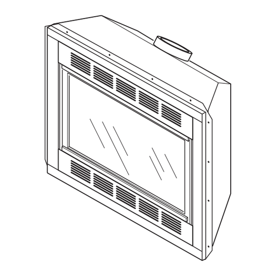
PRODUCT IDENTIFICATION Upper Louver Panel Flue Collar (T32N-A Series) Glass Door Door Screen Assembly (TC32 Series) Glowing Embers Log Set Piezo Ignitor Nailing Control Flange Valve Lava Rock Lower Louver Panel Grate (T32N-A Series) Assembly Blower Switch ON/OFF/REMOTE Switch (Optional Installation) (Optional Installation) Figure 1 - Direct-Vent Fireplace with Millivolt Ignition LOCAL CODES... -
Page 6: Pre-Installation Preparation
Be sure Determine the safest and most efficient location to clear vent termination area after snow falls for your FMI PRODUCTS, LLC direct-vent fire- to prevent accidental blockage of venting place. Make sure that rafters and wall studs are system. - Page 7 PRE-INSTALLATION PREPARATION Continued NOTICE: This fireplace is in- tended for use as supplemental " " " heat. Use this fireplace along " with your primary heating sys- tem. Do not install this fireplace as your primary heat source. " If you have a central heating "...
-
Page 8: Location Of Termination Cap
LOCATION OF TERMINATION CAP Fixed Openable Fixed Closed Closed Openable TERMINATION CAP GAS METER RESTRICTED AREA AIR SUPPLY INLET (TERMINATION PROHIBITED) A = clearance above grade, veranda, porch, deck, or I = clearance to service regulator vent outlet [*72" (182.9 cm) balcony [*12"... -
Page 9: Requirements For The Commonwealth Of Massachusetts
REQUIREMENTS FOR THE COMMONWEALTH OF MASSACHUSETTS INSPECTION For all side wall horizontally vented gas fueled equipment installed in every dwelling, building or The state or local gas inspector of the side structure used in whole or in part for residential wall horizontally vented gas fueled equipment purposes, including those owned or operated by shall not approve the installation unless, upon... -
Page 10: Venting Installation
Failure to do so could result in These models are tested and approved for serious injury, property damage use with FMI PRODUCTS, LLC (direct-vent) pipe components and terminations. or loss of life. The venting system must terminate on the... -
Page 11: Installation Planning
VENTING INSTALLATION Continued INSTALLATION PLANNING 5. Carefully determine location where vent pipe assembly will penetrate the outside There are two basic types of direct-vent wall. The center of hole should line up with installation: center line of horizontal vent pipe. Mark •... - Page 12 VENTING INSTALLATION Continued 6. Noncombustible Exterior Wall: Position Slide wall firestop against interior wall horizontal vent cap in center of the 8 " surface and attach with screws provided round hole and attach to exterior wall with (see Figure 12). See Figure 13, page 13, four screws (see Figure 10).
- Page 13 VENTING INSTALLATION Continued GROUND FLOOR INSTALLATION Siding Recommended Applications: Standoff • Installation using cabinet surrounds Minimum Pipe • Through the wall using round or square Screws Overlap 1 " termination (up to 12") adjustable pipe) • NOT FOR CORNER INSTALLATION Wall 45°...
- Page 14 VENTING INSTALLATION Continued CORNER INSTALLATION Recommended Applications: • Corner ground floor installation • Ground floor installation where pipe vents horizontally through wall (over 12" horizontal pipe) • Basement installation where one foot clearance from ground to termination is possible Not to Exceed 90°...
- Page 15 VENTING INSTALLATION Continued HORIZONTAL SYSTEM INSTALLATION USING TWO 90° ELBOWS The following configurations show the minimum vertical rise requirements for a horizontal system using two 90° elbows. Venting with Two 90° Elbows Horizontal (H Vertical (V) Horizontal (H Horizontal (H 5' min.
-
Page 16: Installation For Vertical Termination
VENTING INSTALLATION Continued INSTALLATION FOR VERTICAL Flat Ceiling Installation 1. Cut a 11 " square hole in ceiling using TERMINATION locating hole as a center point. Opening Note: Vertical restrictor must be installed in should be framed to 11 " x 11 "... - Page 17 VENTING INSTALLATION Venting with One 90° Elbow Vertical (V) Horizontal (H) Continued 5' min. 2' max. vent pipe to combustible materials. 6' min. 4' max. 6. Continue to add pipe sections until height 7' min. 6' max. of vent cap meets the minimum building 8' min.
- Page 18 Note: Install restrictor into inner PARTS LIST FOR VENTING KITS collar of fireplace AND COMPONENTS as shown. FMI PRODUCTS, LLC (5"/8") Pipe & Vent Kits Number Description P58-6 6" Section Double Wall Pipe, Galvanized P58-12 12" Section Double Wall Pipe, 45°...
-
Page 19: Fireplace Installation
VENTING INSTALLATION Continued Number Description Number Description VKC-58 Corner Vent Kit, Galvanized ST-58-14 14" Snorkel Termination, Galva- (Includes 45° Elbow, 7"-12" nized Adjustable Pipe, Wall Firestop, ST-58-36 36" Snorkel Termination, Galvanized Horizontal Termination, 6" Pipe, SC-58 Storm Collar, Galvanized 90° Elbow, 18 Screws) WF-58 Wall Firestop, Galvanized HHTK-58 High Wind Round Horizontal Termi-... - Page 20 FIREPLACE INSTALLATION Continued 4. Be certain that all wire terminals are 9. Check to make sure that power cord is securely attached to terminals on blower completely clear of blower wheel and motor and that screw retaining green that there are no other foreign objects in ground wire is tight.
- Page 21 FIREPLACE INSTALLATION Continued 3. Place the blower against the lower rear 7. Check to make sure that power cord is wall of the firebox outer wrapper with completely clear of blower wheel and the exhaust port directed upward. Attach that there are no other foreign objects in Thermal disc magnetic bracket to the bot- blower wheel.
- Page 22 FIREPLACE INSTALLATION Continued INSTALLING GAS PIPING TO fireplace regulator damage could occur. Install external regulator with the vent pointing down FIREPLACE LOCATION as shown in Figure 31. Pointing the vent down protects it from freezing rain or sleet. WARNING: A qualified service person must connect CAUTION: Use only new, fireplace to gas supply.
- Page 23 FIREPLACE INSTALLATION Continued We recommend that you install a sediment To Gas Supply trap/drip leg in supply line as shown in Figure (Natural) Equipment 32. Locate sediment trap/drip leg where it is Shutoff within reach for cleaning. Install in piping sys- Valve Control Valve tem between fuel supply and fireplace.
- Page 24 FIREPLACE INSTALLATION PRESSURE TESTING FIREPLACE GAS CONNECTIONS Continued 1. Open equipment shutoff valve (see Fig- Test Pressures Equal To or Less Than ure 34). 1/2 PSIG (3.5 kPa) 2. Open main gas valve located on or near 1. Close equipment shutoff valve (see Fig- gas meter for natural gas or open supply ure 34).
- Page 25 FIREPLACE INSTALLATION Continued 2. Remote receiver can be placed in the Removing Louver Panels hole on the switch bracket or place on the Remove top and bottom louver panels by floor underneath the firebox. See remote simultaneously pulling both top end spring instructions for further information.
-
Page 26: Brick Panels
FIREPLACE INSTALLATION INSTALLING OPTIONAL BRICK Continued LINER MODEL BL32D Press in on the bottom of door screen until WARNING: If fireplace has magnetic door latch is pushed in. been running, turn off and un- Removing Glass Door plug fireplace. Let cool before If replacement of glass is necessary, the installing brick liner. - Page 27 FIREPLACE INSTALLATION 2. Rest log #2 (front log) on pins on front part of grate (see Figure 45). Continued 8. Replace deflector shield using screws removed in step 4. 9. Follow instructions below to install logs, lava rock and ember material. 10.
-
Page 28: Operation
FIREPLACE INSTALLATION Continued 5. Place log #5 (base log) onto front left part 8. Pull ember material apart into pieces no larger than a dime. Place these pieces of grate making sure log fits over metal pin loosely and sparingly directly onto ex- of grate. - Page 29 OPERATION Continued LIGHTING TO TURN OFF GAS INSTRUCTIONS TO APPLIANCE 1. STOP! Read the safety information on 1. Open lower louver panel. page 28. 2. Set selector switch in the OFF position to 2. Open lower louver panel. prevent draining battery. 3.
-
Page 30: Inspecting Burners
OPERATION Continued Blower Control Knob blower with optional thermostat (wall mounted Variable (Optional Accessory) or remote control) for the fireplace, your fire- Control Knob place and blower will not turn on and off at the same time. Fireplace may run for several minutes before blower turns on. -
Page 31: Cleaning And Maintenance
INSPECTING BURNERS Continued If the vent configuration is installed incorrectly, WARNING: Do not use flames will lift or "ghost". This can be danger- ous. Inspect flames after installation to ensure abrasive cleaners as this may proper installation and performance. damage glass. Use a nonabra- Figure 53 shows a typical flame pattern. -
Page 32: Cleaning And Maintenance
CLEANING AND MAINTENANCE Continued VENTING SYSTEM Use only the tempered glass door replace- ment intended for this fireplace (see Replace- Conduct annual inspection of venting system ment Parts, page 33 for detail on ordering). No following these guidelines: substitutions may be made. See Removing/ 1. -
Page 33: Replacement Parts
You may have further questions about • pilot will not stay lit installation, operation, or troubleshooting. If so, contact FMI PRODUCTS, LLC at • burners will have delayed ignition 1-866-328-4537. When calling please have • fireplace will not produce specified heat your model and serial numbers of your •... -
Page 34: Troubleshooting
TROUBLESHOOTING WARNING: Turn off heater and let cool before servicing. Only a qualified service person should service and repair heater. CAUTION: Never use a wire, needle or similar object to clean pilot. This can damage pilot unit. Note: All troubleshooting items are listed in order of operation. OBSERVED PROBLEM POSSIBLE CAUSE REMEDY... - Page 35 TROUBLESHOOTING Continued OBSERVED PROBLEM POSSIBLE CAUSE REMEDY Pilot lights but flame goes 1. Gas control knob not fully 1. Press in gas control knob out when control knob is pressed in fully released 2. G a s c o n t r o l k n o b n o t 2.
- Page 36 TROUBLESHOOTING Continued POSSIBLE CAUSE OBSERVED PROBLEM REMEDY 1. Turning gas control knob Heater produces a whistling 1. Turn gas control knob to LO to HI position when burner noise when burner is lit position and let warm up for is cold a minute 2.
- Page 37 TROUBLESHOOTING Continued WARNING: If you smell gas • Shut off gas supply. • Do not try to light any appliance. • Do not touch any electrical switch; do not use any phone in your building. • Immediately call your gas supplier from a neighbor’s phone. Fol- low the gas supplier’s instructions.
-
Page 38: Parts
PARTS MODELS (V)T32N-A, (V)T32NB-A, (V)T32NR-A, (V)T32NRB-A, (V)T32P-A, (V) T32PB-A, (V)T32PR-A, (V)T32PRB-A, (V)TC32(N)(P), (V)TC32(NB)(PB), (V) TC32N-HA, CGDV32NR, CGDV32PR AND CTDV32NR-HA 22-3 22-5 22-4 22-6 22-2 22-1 www.fmiproducts.com 116646-01M... - Page 39 PARTS This list contains replaceable parts used in your fireplace. When ordering parts, follow the instructions listed under Replacement Parts on page 33 of this manual. PART NUMBER CGDV32NR CGDV32PR CTDV32NR-HA (V)T32NR-A (V)T32PR-A (V)T32NRB-A (V)T32PRB-A (V)T32N-A (V)T32P-A (V)TC32(N)(P) (V)T32NB-A (V)TC32(NB)(PB) (V)T32PB-A (V)TC32N-HA DESCRIPTION...
- Page 40 PARTS BURNER ASSEMBLY MODELS (V)T32N-A, (V)T32NB-A, (V)T32NR-A, (V) T32NRB-A, (V)T32P-A, (V)T32PB-A, (V)T32PR-A, (V)T32PRB-A, (V)TC32(N) (P), (V)TC32(NB)(PB), TC32N-HA CGDV32NR, CGDV32PR AND CTDV32NR-HA www.fmiproducts.com 116646-01M...
- Page 41 PARTS BURNER ASSEMBLY MODELS (V)T32N-A, (V)T32NB-A, (V)T32NR-A, (V) T32NRB-A, (V)T32P-A, (V)T32PB-A, (V)T32PR-A, (V)T32PRB-A, (V)TC32(N)(P), (V)TC32(NB)(PB), (V)TC32N-HA, CGDV32NR, CGDV32PR AND CTDV32NR-HA This list contains replaceable parts used in your fireplace. When ordering parts, follow the instructions listed under Replacement Parts on page 33 of this manual. NO.
-
Page 42: Accessories
Purchase these accessories from your local dealer. If they can not supply these accessories call FMI PRODUCTS, LLC at 1-866-328-4537 for information. You can also write to the ad- dress listed on the back page of this manual. REFRACTORY BRICK LINER KIT... - Page 43 NOTES _____________________________________________________ _____________________________________________________ _____________________________________________________ _____________________________________________________ _____________________________________________________ _____________________________________________________ _____________________________________________________ _____________________________________________________ _____________________________________________________ _____________________________________________________ _____________________________________________________ _____________________________________________________ _____________________________________________________ _____________________________________________________ _____________________________________________________ _____________________________________________________ _____________________________________________________ _____________________________________________________ _____________________________________________________ _____________________________________________________ _____________________________________________________ _____________________________________________________ _____________________________________________________ _____________________________________________________ _____________________________________________________ _____________________________________________________ _____________________________________________________ _____________________________________________________ _____________________________________________________ _____________________________________________________ _____________________________________________________ _____________________________________________________ _____________________________________________________ _____________________________________________________ www.fmiproducts.com 116646-01M...
-
Page 44: Warranty
FMI PRODUCTS, LLC’s liability is limited to the purchase price of the product, and FMI PRODUCTS, LLC shall not be liable for any other damages whatsoever under any circumstances including indirect, incidental, or consequential damages.
Need help?
Do you have a question about the Tudor VT32N-A Series and is the answer not in the manual?
Questions and answers