
Related Manuals for SpeakerCraft MZC-66


Summary of Contents for SpeakerCraft MZC-66
- Page 1 HARDWARE INSTALLATION INSTRUCTIONS MZC-66 Multi-Zone Audio/Video Amplifi er Controller...
-
Page 2: Safety Instructions
Page 2 MZC-66 Hardware Installation Instructions SAFETY INSTRUCTIONS CAUTION RISK OF ELECTRIC SHOCK DO NOT OPEN CAUTION: To reduce the risk of electric shock, do not remove cover, (or back). No user serviceable parts inside. Refer servicing to qualifi ed service personnel. -
Page 3: Table Of Contents
EZ-PAD ..............................7 IMKP ..............................7 MODE 3.1 .............................7 EZ-PAD FEATURE DESCRIPTIONS ..................8 MZC-66 FRONT PANEL ....................10 MZC-66 REAR PANEL ..................... 11 EPR-1.0 EZ-PAD RELAY MUTING MODULE ..............13 TYPICAL MZC-66 SYSTEM ....................14 SYSTEM PLANNING AND INSTALLATION ................ 15 SYSTEM PLANNING ....................... - Page 4 CONNECTIONS - ZONES ........................26 Keypads ................................26 Speakers ................................26 Direct Speaker Connection To MZC-66 Or Amplifi er ...................26 Sub-Zone Expansion, Multi-Channel Amplifi er - NVC, Fixed Output ..............26 Zone IR Out ..............................26 Speaker Connection To EPR-1.0 EZ-Pad Relay Muting Module ................27 Other Zone Connections ..........................27...
-
Page 5: Introduction
Thank you for purchasing the SpeakerCraft MZC-66 Multi-Zone Audio/Video Amplifi er Controller. The MZC-66 contains the excellent performance and reliability that SpeakerCraft products have been recognized for. The MZC-66 features the fl exibility needed for the most demanding custom installation applications. It is ideal for use in residential and commercial multi-zone applications. -
Page 6: Product Features
Page 6 MZC-66 Hardware Installation Instructions PRODUCT FEATURES • 6 Independent Zones (Expandable to 24) • 6 External Audio/Video Source Inputs • 12 Channel Audio Amplifier @ 30 watts per channel • Source Power Management • Whole-House Party and Control Modes •... -
Page 7: System Overview
MODE 3.1 The third, and best option for MZC-66 system control, is the SpeakerCraft MODE 3.1. MODE 3.1 is a graphic display keypad that combines the convenience and confi gurability of EZ-Pad/IMKP style hard keys with graphic ‘Virtual Buttons’ that can be created in EZ-Tools for any function imaginable. -
Page 8: Ez-Pad Feature Descriptions
EZ-Pads come in four basic modules as shown. The MKP-1.0 and MKP-1.1 are Master Keypads and one must be used in each MZC-66 Zone using a keypad. The MKP-1.1 features a built-in IR receiver and has one less function button than the MKP-1.0, but are otherwise identical. - Page 9 Also allows attachment of standard and screw-less, snap-on decorator type cover plates. 6. IR RECEIVER LENS – The MKP-1.1 includes SpeakerCraft’ s exclusive ANS (Ambient Noise Suppressor) IR Receiver, built-in. The IR Receiver allows use of a handheld remote for control of the system and IR controlled source components.
-
Page 10: Mzc-66 Front Panel
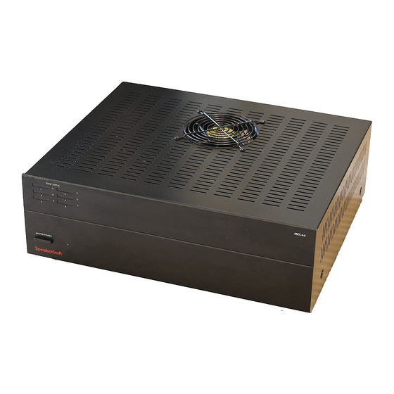
MZC-66 FRONT PANEL The MZC-66 is an 6-Zone, 6-Source Audio/Video Amplifi er Controller. It serves as the “brains” of the entire keypad system and provides audio and video switching and control for up to six external sources. Twelve 30W/channel digital audio power amplifi... -
Page 11: Mzc-66 Rear Panel
24 to 14 AWG. Internal relay contacts are rated at 2A/30V AC or DC. 2. EXPANSION PORT/LOOP — Two, RJ45 jacks primarily used for looping system data to multiple MZC-66’ s in expanded systems. These jacks can also be used for connection of specialized RS485 controlled products such as the SpeakerCraft MODE Base for adding iPods and additional Sources. - Page 12 Slave MZC-66’ s in expanded systems. i.e. The L, R, V LOOP on the MZC Master would connect to the appropriate L, R, V INPUT on MZC Slave 1.
-
Page 13: Epr-1.0 Ez-Pad Relay Muting Module
The EPR-1.0 EZ-Pad Speaker Muting Relay Module allows local speaker muting in any room with an EZ-Pad. Example: An MZC-66 Zone PRE-OUT feeding a multi-channel amplifi er for sub-zone expansion. Each of the additional ‘rooms’ would utilize one stereo pair speaker-level output from the multi-channel amp, have a keypad for system and source control and each key- pad would have an EPR-1.0 to mute the local speakers. -
Page 14: Typical Mzc-66 System
TYPICAL MZC-66 SYSTEM IPod MODE SATELLITE MODE JUKEBOX BASE SpeakerCraft IRE Series Stereo Line Level Audio/ IR Emitter Composite Video From MZC-66 Source IR Out From Source Out To MZC-66 Source In MODE PS-1.0 200mA ADAPTER CABLE Power Supply RS232 DATA I/O 12VDC RSA-1.0... -
Page 15: System Planning And Installation
SYSTEM PLANNING AND INSTALLATION SYSTEM PLANNING With all of the fl exibility and options of a MZC-66 System, careful planning can save time and money for both the installer and homeowner. A few EZ steps can help in managing this process. - Page 16 Incorporate a proper ventilation system using cooling fans (SpeakerCraft ESC-1) for systems with external amplifi ers or other components that generate excess heat. When possible, leave extra space for future expansion of the system for additional zone and source components.
-
Page 17: System Installation
Once the system has been defi ned and the contract signed, work can begin. The fi rst part of the system to be installed is the wiring infrastructure. With all of the fl exibility and options of a MZC-66 System, maintaining clear, accurate documentation of the location (the house) and the system will help in managing a smooth installation. -
Page 18: Speakers
(6mm) on both ends of the individual conductors to be used for connection to the EZ-Pads/IMKPs and MZC-66. For MODE 3.1, secure each lead end (without stripping) to the proper terminal with a punchdown tool. MODE 3.1 CAUTION: Use only 24AWG solid wire. Larger sizes may damage the terminals and stranded wire will not retain securely. -
Page 19: Phone Page In
Installation - Connect one end of the pre-made video cable to the camera/video device composite video out and the other to the VIDEO PAGE IN jack on the MZC-66 Rear Panel. Terminate the RG6 with an RCA connector at the System Head-End. -
Page 20: Source Ir Out
LOOP to MZC-66 SLAVE 1, Source 1, L & R line-level audio and composite video INPUT; MZC SLAVE 1, Source 1, L & R line-level audio and composite video LOOP to MZC-66 SLAVE 2, Source 1, L & R line-level audio and composite video INPUT. -
Page 21: Ez-Pad Configuration
MZC-66 Hardware Installation Instructions Page 21 EZ-PAD CONFIGURATION 1. As received from the factory, the MKP-1.1 EZ-Pads have a preinstalled set of buttons that may not match the system being installed. To change the source and function button arrangement, release the tabs, Figure 7, and remove the decorator insert panel, exposing the key buttons. - Page 22 MZC-66 Hardware Installation Instructions 5. When connecting keypads to the MZC-66 as shown in Figure 12, be sure to connect the various colored CAT-5 leads to the correct Terminals on each end. Use the same colors scheme for all zones to help reduce errors.
-
Page 23: Installation
1. Carefully attach a SpeakerCraft IR Emitter (Models: 1.0, 2.0, 3.0, 4.0) over the IR eye on the front panel of each exter- nal source component to be controlled via infrared. 2. Carefully pull the emitter wire to the back of the MZC-66. Do not block accesses for discs and tapes. Do not pinch emitter wires between components. -
Page 24: Video Output
1. Connect the composite video OUT of an appropriately featured front door panel, camera or other video source to the Video Page In jack on the MZC-66 Rear Panel. If the camera or video source is in close proximity to the MZC-66, use a quality RCA-RCA cable for connections up to 15’... -
Page 25: Common Ir Out
5. To drive an IRE-5.0 Blaster, see IR Blaster, below. IR EMITTER 1. Carefully attach a SpeakerCraft IR Emitter (Models: IRE- 0.5, 1.0, 2.0, 3.0, 4.0) over the IR eye on the front panel of common source component to be controlled via infrared. -
Page 26: Installation - Zones
1. Carefully attach a SpeakerCraft IR Emitter (Models: IRE- 0.5,1.0, 2.0, 3.0, 4.0) over the IR eye on the front panel of a dedicated zone source component to be controlled via infrared. 2. Carefully pull the emitter wire to the back of the MZC-66. Do not block accesses for discs and tapes. Do not pinch the emitter wire between components. -
Page 27: Speaker Connection To Epr-1.0 Ez-Pad Relay Muting Module
MZC-66 Hardware Installation Instructions Page 27 SPEAKER CONNECTION TO EPR-1.0 EZ-PAD RELAY MUTING MODULE 1. Connect Zone Speakers L+,L-/R-,R+ OUTPUTS from the MZC-66 or an external amplifi er to the EPR-1.0 Amplifi er Terminal L+,L-/R-,R+ INPUTS. (Refer to Figure 19) 2. Strip approximately ⁄... -
Page 28: External Amplifiers
There are two methods of 12V control from a MZC-66. One method utilizes the Contact Closure pair as an ‘Event’ to turn the amplifi er on and off with a specifi c zone. The other allows use of the MZC-66 Common Status Out. This second option will have the amplifi... - Page 29 12V TRIGGER (SYSTEM ACTIVITY) 1. Connect a 3.5mm mini-mini plug wire (SpeakerCraft PTP-1) to the MZC-66 Common Status OUT. 2. If using a SpeakerCraft BB2125, plug the other end into the Trigger Input jack. Switch the Audio Sense/Trigger/Con- stant Switch to Trigger Input.
-
Page 30: Adding A 12-Channel Amplifier To A Zone
There are two methods of 12V control from a MZC-66. One method utilizes the Contact Closure pair as an ‘Event’ to turn the amplifi er on and off with a specifi c zone. The other allows use of the MZC-66 Common Status Out. This second option will have the amplifi... - Page 31 1. Using a quality stereo RCA to RCA cable, connect the Zone L & R Pre-Outs to the appropriate L & R line level inputs (i.e. Channel pairs 1 and 2, Channel pairs 3 and 4, etc.) on the multi-channel amp. 2. Set the VC/NVC Switches on the MZC-66 Rear Panel to VC (variable) so the zone keypads can be used to adjust volume.
-
Page 32: Expanded Systems
EXPANDED SYSTEMS Up to four MZC-66s can be “daisy-chained” together to create systems with up to 24 Zones. The fi rst MZC-66 in the chain is referred to as the Master and the subsequent MZC-66’ s are referred to as Slaves. System Zone numbers correspond to the... - Page 33 PRE-OUT PRE-OUT IR OUT IR OUT IR OUT IR OUT IR OUT IR OUT 120V 60Hz EZ-PAD EZ-PAD EZ-PAD EZ-PAD EZ-PAD EZ-PAD SPEAKERS SPEAKERS SPEAKERS SPEAKERS SPEAKERS SPEAKERS FUSE: T5AL 250V Figure 17 MZC-66 Expanded System Source, Audio, Control Connections...
- Page 34 VIDEO VIDEO DISPLAYS DISPLAYS MODE 3.1 MKP-1.1 Riverside, CA www.speakercraft.com J-Box EZ-Pad w/IRC Zones 7-12 MADE IN CHINA Zones 7-12 -Master- SpeakerCraft + RELAY - RELAY 485 A 485B KEYPADS Zones 7-12 Figure 18 MZC-66 Expanded System Speaker, Keypad Connections...
- Page 35 EXPANSION PORT Terminals on the MZC-66 MASTER to one of the EXPANSION PORT Terminals on the next MZC-66 Slave in the chain. (Master to Slave 1, Slave 1 to Slave 2, etc.) NOTE: The Expansion Ports on a given MZC are parallel, so either can be used for expansion connections.
- Page 36 ”) Y adaptors for IR control of a common device (not connected to one of the Source Inputs) from any MZC-66 in the chain. NOTE: This application requires standard Y adaptors. DO NOT use the SpeakerCraft SAC-1.0 Y Adapter. The SAC-1.0 has ‘steering’...
-
Page 37: Common Status Out
‘steering’ diodes that will interfere with the signal path in this application. 1. Daisy-chain the Y adaptors to the Common STATUS OUTS on all MZC-66’ s in the chain as shown in Figure 22. 2. Connect a trigger wire to the Y adaptor assembly as shown in Figure 22. -
Page 38: Troubleshooting
Confi rm Doorbell/Status In programming in EZ-Tools. Control From Keypads a) Confi rm MZC-66 has AC power and is turned on. a) Confi rm keypad connection to MZC-66. c) Confi rm polarity of keypad connections. d) Confi rm zone keypad programming in EZ-Tools. -
Page 39: Mzc-66 Specifications
MZC-66 Hardware Installation Instructions Page 39 MZC-66 Specifi cations Audio Sections Power Output/Channel (RMS, two channels driven into 8 Ohms) 30 Watts, 20Hz to 20kHz THD (at rated power) <0.7% Power/Channel (RMS, 2 channels driven into 4 Ohms) 45 Watts @ 1kHz... -
Page 40: Limited 2-Year Warranty
In no event will SpeakerCraft be liable for any incidental or consequential damages arising out of the use or inability to use the product, even if SpeakerCraft Inc. or a SpeakerCraft Inc.
Need help?
Do you have a question about the MZC-66 and is the answer not in the manual?
Questions and answers