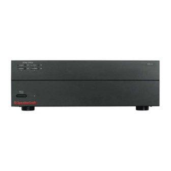
SpeakerCraft MZC-64 Quick Start Manual
Multi-zone amplifier controller
Hide thumbs
Also See for MZC-64:
- Quick install manual (2 pages) ,
- Installation instructions manual (39 pages) ,
- Hardware installation instructions (39 pages)
Advertisement
Quick Links
QUICK START GUIDE
MZC-64
Multi-Zone Amplifier Controller
ABOUT MZC-64 QUICK START GUIDE
MZC-64 QUICK START GUIDE is intended to provide top-level instructions for Installation, Configuration and
Connection of a SpeakerCraft MZC-64 System. MZC-64 Quick Start focuses on a MZC-64 'default' system, that
is, a basic four zone system that includes up to six audio sources, that matches the EZ-Tools MZC-64 MODE De-
fault_306 Project. This Quick Start Guide can also be used for getting more sophisticated systems started, but
when planning and installing expanded systems with multiple controllers, external amplifiers, multi-room zones
or when changing the layout of the keypad buttons, it is highly recommended that the MZC-64 Hardware In-
stallation Instructions be used for reference and guidance. Additionally, the Hardware Installation Instructions
provide much greater detail in regard to instructions given here. MZC-64 Hardware Installation Instructions are
available as a download from www.speakercraft.com.
Once a MZC system has been installed, it must be programmed with SpeakerCraft's EZ-Tools Programming
Software. EZ-Tools MZC Programming Instructions are available as a download from www.speakercraft.com.
Advertisement

Summary of Contents for SpeakerCraft MZC-64
-
Page 1: Quick Start Guide
Connection of a SpeakerCraft MZC-64 System. MZC-64 Quick Start focuses on a MZC-64 ‘default’ system, that is, a basic four zone system that includes up to six audio sources, that matches the EZ-Tools MZC-64 MODE De- fault_306 Project. This Quick Start Guide can also be used for getting more sophisticated systems started, but... - Page 2 MASTER POWER Switch – When pressed to the in position, the MZC-64 is placed in the power ON standby condition, permitting individual zones to be turned ON and OFF by keypad or touch panel commands. In the OFF (out) position, power from the AC mains is completely turned off.
- Page 3 16. IR LOOP – Six, 3.5mm mini jacks, one per Source, provide connections for an IR signal path for external common source com ponents, when using multiple MZC-64’s in expanded systems. i.e. If using two MZC-64s, the SOURCE IR OUTS on the MZC Slave unit would connect to the appropriate SOURCE IR LOOPS on the MZC Master unit to pass Source IR commands between con trollers from expanded zones.
- Page 4 Function Buttons – These lower 5 buttons (4 buttons in the case of the MKP-1.1) can be programmed for any function except source select. IR Receiver Lens – EZ-Pad version MKP-1.1 includes SpeakerCraft’s exclusive ANS IR Receiver, built-in. The IR Receiver allows use of a handheld remote for control of system components.
-
Page 5: Keypad Connections
485A & 485B CAT-5 WITHOUT RJ45 CONNECTORS – Connect EZ-Pads to MZC-64 as shown above. Be sure to maintain consistent color code when making connections. For IMKP use same pin-out. For MODE 3.1 use CAT-5 terminated with RJ45 connectors in a pin to in (pass- through) configuration. -
Page 6: Typical Mzc-64 System
EZ-Tools. High power or multi-channel amplifiers can be added to the individual zones for high audio output in large rooms or outdoor zones or when adding additional rooms or “sub-zones” to a default system. Additionally, the MZC-64 has a program- mable contact closure for control of lifts, screens, drapes etc. - Page 7 Carefully attach a SpeakerCraft IR Emitter (Models: IRE-0.5, 1.0, 2.0, 3.0, 4.0) over the IR eye on the front panel of each external source component to be controlled via infrared. Carefully pull the emitter wire to the rear panel of the MZC-64. Do not block accesses for discs and tapes. Do not pinch emitter wires between components.
- Page 8 11.5 V Active High, 390 Ohms Common Status Out 9.5 V @ 100 mA (0 to 12 VDC) 940 Columbia Ave., Riverside CA 92507 | USA (800) 448 0976 Fax (951) 787 8747 International +1 951 787 0543 | www.speakercraft.com LIT13164(rev1)


Need help?
Do you have a question about the MZC-64 and is the answer not in the manual?
Questions and answers