Advertisement
Advertisement
Table of Contents

Summary of Contents for SpeakerCraft Big Bang BB835
- Page 1 Big Bang Power Amplifiers B B 8 3 5 O w n e r ’ s M a n u a l...
-
Page 2: Table Of Contents
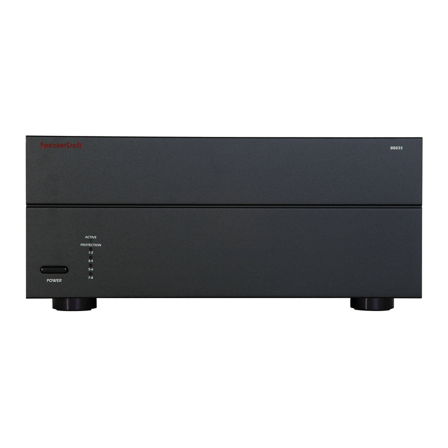
Each channel has its own level adjustment. This allows the loudness of each Installation Considerations speaker to be perfectly matched to its area. Installation InstaLLock ™ Connector Outputs Simplify the connection of the speaker outputs by using SpeakerCraft’ s InstaLLock ™ Connector, purchased separately. InstaLLock ™ Connectors elimi- Operation nate the hassle of connecting multiple wires onto the back of the amplifier. - Page 3 Diagram 1 - Front Panel Active LED indicates that the amplifier is working. Master power switch. Turns off power to amplifier and Power Mode Circuitry. Protection LEDs indicate that either a fault in the wiring, the speaker, or the amplifier has caused the amplifier to shut down.
- Page 4 Diagram 2 - Rear Panel Bridging switch allows Bus outputs allow the you to easily double bus inputs to be sent the power output by to other amplifiers or a coupling two chan- daisy chain without the nels together. need for ‘Y’ cables or One switch allows you Main bus inputs allow outputs from splitters.
-
Page 5: System Design & Operation Considerations
Bus Input SYSTEM DESIGN & OPERATION CONSIDERATIONS Allows the signal from a source to be distributed to any of the 12 channels on the amplifier. To best understand system design and operation of the BB835 it is useful to understand the following terms and features as they relate to the BB835. Auxiliary Inputs Allows a the signal from a secondary source to be distributed to any of the 12 Multi-Room... -
Page 6: System Design Examples
SYSTEM DESIGN EXAMPLES There are many ways to configure the BB835 amplifier. The following pages contain some typical installation examples. Use these examples to generate ideas for your system design. Multi-Room Installation Example (Diagram 4) This illustrates the simplest use of the BB835, distributing audio throughout the home. - Page 7 Diagram 4 - Multi-Room Installation AUDIO SOURCES OUTPUT PREAMPLIFIER / RECEIVER CD Player TAPE INPUT INPUT INPUT OUTPUT OUTPUT Tape Deck OUTPUT DVD Player Room 1 Room 2 Room 3 Room 4 VOLUME CONTROL VOLUME CONTROL VOLUME CONTROL VOLUME CONTROL LEFT SPEAKER RIGHT SPEAKER LEFT SPEAKER...
- Page 8 Diagram 5 - Multi-Zone Installation #1 SOURCES OUTPUT PREAMPLIFIER / RECEIVER CD Player #1 TAPE OUTPUT INPUT INPUT INPUT INPUT OUTPUT Tape Deck OUTPUT CD Player #2 DVD Player OUTPUT VOLUME CONTROL VOLUME CONTROL VOLUME CONTROL VOLUME CONTROL LEFT SPEAKER RIGHT SPEAKER LEFT SPEAKER RIGHT SPEAKER...
- Page 9 Diagram 6 - Multi-Zone Installation #2 CD Player DVD Player Tuner Tape Deck OUTPUT OUTPUT OUTPUT OUTPUT AUDIO SOURCES TUNER TAPE INPUT INPUT INPU INPUT INPUT 4 STEREO PREAMPLIFIERS MULTIZONE PREAMPLIFIER ZONE 1 ZONE 2 ZONE ZONE 3 ZONE 4 OUTPUT OUTPUT OUTP...
- Page 10 Diagram 7 - Home Theater/Multi-Room Installation SOURCES OUTPUT HOME THEATER RECEIVER CD Player SPEAKER SUBWOOFER MULTI-ROOM OUTPUTS OUTPUT OUTPUT INPUT INPUT INPUT INPUT REAR REAR OUTPUT LEFT CENTER RIGHT LEFT RIGHT DVD Player OUTPUT LEFT SPEAKER CENTER SPEAKER RIGHT SPEAKER REAR LEFT SPEAKER SUBWOOFER REAR RIGHT SPEAKER...
-
Page 11: Installation Considerations
Placement INSTALLATION CONSIDERATIONS INSTALLATION CAUTION: All connections and switching must be done with the amplifier’ s master power switch positioned to “off”. • Place the amplifier with the feet resting on a solid flat level surface. • Place the amplifier in a well-vented area to provide proper cooling. In Select the Power Mode Selection areas that lack proper ventilation, such as tight cabinets or racks, it may Refer to the Power Mode Selection area under installation considerations to... - Page 12 Selecting Inputs (See Diagrams 8 & 9) Selecting Bridge Mode (See Diagram 11) Each channel is capable of delivering the source from many inputs. The three main inputs are BUS, AUX and LINE IN. The selection for these inputs is done Under normal operation, this should be left in the 8 ohm position as illustrat- via the Input Selection switch, marked “BUS-AUX-LINE”.
-
Page 13: Operation
3.5mm jack. Be aware that the tip of the plug will be (+). If you are components or amplifiers by connecting to the corresponding output sections unsure about using this feature please contact an authorized SpeakerCraft to the right of each input section. By using standard audio patch cables, you dealer for assistance. -
Page 14: Troubleshooting
If you have a problem please check the trou- clockwise to raise the volume. bleshooting list first. If the problem persists, contact your authorized SpeakerCraft dealer or SpeakerCraft customer service at (800) 448-0976. Some or all of the internal fuses are blown. Return the amplifier to your SpeakerCraft dealer for servicing. -
Page 15: Specifications
If this model is no longer available and can not be repaired effectively, SpeakerCraft, at its sole option may replace the unit with a current model of equal or greater value. In some cases where a new model is substituted, a modification to the mounting surface may be required. - Page 16 940 Columbia Ave., Riverside, CA 92507-4492 SpeakerCraft ® (800) 448-0976, Fax (951) 787-8747 www.speakercraft.com LIT 9/00...


Need help?
Do you have a question about the Big Bang BB835 and is the answer not in the manual?
Questions and answers