Advertisement
Quick Links
SmartPath
™
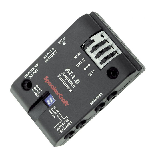
AT-1.0
Amplified Terminator
INSTALLATION INSTRUCTIONS
The AT-1.0 provides a convenient means of interconnecting
SpeakerCraft (and industry compatible) IR products in IR repeating
systems. It includes a wide bandwidth amplifier for robust operation.
It has blaster drive power capability and is reverse voltage protected.
1
8
J4
J5
AT-1.0
AMPLIFIED
7
J6
TERMINATOR
SpeakerCraft
®
6
J7
EM ON
BL ON
EM ON
BL ON
NET OFF
NET ON
2
J8
5
FEATURE DESCRIPTIONS (Refer to Fig. 1)
1. Spring-loaded EZ-Connect Terminals accept wire sizes 14 to 28
AWG for connection of the following:
• +12V DC – Powers connected IR Receivers, Keypads, etc.
• GND – Return for Power, IR signal and Status indicators
• ST OUT – Connects status voltage to Status Indicators in
IR Receivers, Keypads, etc.
• IR IN – Receives IR control signals from IR Receivers,
Keypads, etc.
2. Mounting Holes – Attaches the AT-1.0 to any flat surface using
the two screws provided.
3. EMITTERS – Two 3.5mm jacks drive two emitters at medium
power.
4. EMITTERS/BLASTERS – Two 3.5mm jacks drive two emitters at
medium power or two blasters at very high power.
5. DIP Switch (3 position) – The upper two positions switch between
emitter power (EM ON) and blaster power (BL ON) for the two corre-
sponding EMITTERS/BLASTERS jacks.
CAUTION: The BL ON position sets the AT-1.0 to very high blaster
power. Be sure to return the DIP switch to Emitter On (EM ON)
position when driving normal emitters. Failure to do so will
smoke the emitters!
Network Terminator. The bottom DIP position allows the IR IN and
IR RCVR inputs to be terminated with a 500Ω resistor (NET ON), or
un-terminated (NET OFF). The NET ON position should be chosen
when using long lengths of wire (over 50', shielded in particular)
between the IR receiver, keypad, etc. and the AT-1.0. This ensures
best operation for high data rate IR codes. If using two or more
AT-1.0' s in a paralleled network system (see Fig. 4), be sure only
ONE of the AT-1.0 Terminators is set to the NET ON position.
Fig. 1
6. 12V DC REGULATED – 2.1mm jack, center pin +, accepts 12V DC
regulated power supplies to power the IR system. Calculate the current
required, then use SpeakerCraft power supplies PS-1.0 (200 mA) or PS-2.0
(1.2 A). Note: The "no signal" current draw of the AT-1.0 is zero.
2
7. STATUS IN 5-24V DC - 2.1mm jack, center pin +, accepts 5V through
24V DC power supplies to power system ON/OFF Status Indicators of
connected IR receivers, keypads, etc.
3
8. IR RCVR – Exclusive four-circuit 3.5mm jack provides connection for
SpeakerCraft direct plug-in IR Receivers. Connections are made, not only
for Power, Signal and Ground, but for the Status Indicator in the IR
Receivers as well.
4
SYSTEM CONNECTIONS
The following are a few typical applications of the AT-1.0 for IR repeater
systems.
A Basic System
Fig. 2 shows a basic installation, such as controlling components that are
behind closed cabinet doors.
IRC-3.0
Shelf Top
IR Receiver
PS-1.0
Power
Supply
To 120V AC
(unswitched)
Fig. 2
A/V Receiver
Remote Control
IRE-3.0
Visible Emitter
Satellite
J4
J5
AT-1.0
AMPLIFIED
J6
TERMINATOR
IRE-3.0
Visible Emitter
SpeakerCraft
®
J7
DVD
EM ON
BL ON
EM ON
BL ON
NET OFF
NET ON
J8
IRE-3.0
AT-1.0
Visible Emitter
Amplified Terminator
2
1. Plug in the IR Receiver and Emitters as shown.
Note: Since the AT-1.0 employs emitter current sharing, you may use
any of the IRE-1.0, 2.0, 3.0, or 4.0 SpeakerCraft emitters in any
combination you wish.
2. Set the DIP switches to EM ON and NET ON or NET OFF .
3. Plug in the Power Supply.
4. The AT-1.0 system should now control the components.
A Multi-Room System
Fig. 3 is an example of a multi-room (not multi-zone) system. SpeakerCraft IR
receivers in each room, plus a local IR receiver, control the various compo-
nents in the main room or equipment area.
ROOM 1
ROOM 2
IRC-4.0
IRC-2.0
J-Box IR Receiver
Surface Mount IR Receiver
IRC-4.0
Striped
J-BOX
Side
IR RECEIVER
IR OUT
+12V
SpeakerCraft
®
STATUS
GND
Rear View
Add Resistor at each IR receiver
to reduce STATUS brightness,
if desired. See text.
EZ-Connect Terminals
IRC-3.0
Shelf Top IR Receiver
AT-1.0
AMPLIFIED
TERMINATOR
SpeakerCraft
®
EM ON
BL ON
EM ON
BL ON
NET OFF
NET ON
AT-1.0
PS-1.0
Amplified Terminator
Power
Supply
To 120V AC
(unswitched)
CONTROLLED COMPONENTS AREA, MAIN ROOM, ETC.
3
Fig. 3
ROOM 3
IRC-1.1
Flush Mount IR Receiver
IR OUT
+12V
(white)
(red)
STATUS
GND
(yellow)
(black)
To Switched
AC Outlet on
A/V Receiver
A/V Receiver
PS-1.0
IRE-1.0
Emitter
"STATUS"
Satellite
Supply
IRE-3.0
Visible Emitter
DVD
IRE-4.0
Dual
Visible Emitter
To Additional
Controlled Unit
Advertisement

Related Manuals for SpeakerCraft SmartPath AT-1.0


Summary of Contents for SpeakerCraft SmartPath AT-1.0
-
Page 1: Installation Instructions
INSTALLATION INSTRUCTIONS IR RCVR inputs to be terminated with a 500Ω resistor (NET ON), or Fig. 3 is an example of a multi-room (not multi-zone) system. SpeakerCraft IR un-terminated (NET OFF). The NET ON position should be chosen receivers in each room, plus a local IR receiver, control the various compo- when using long lengths of wire (over 50', shielded in particular) nents in the main room or equipment area. - Page 2 2. Connect the local IR receivers in each room to the IR RCVR jacks or in you will need to use the SpeakerCraft PS-2.0 12V DC 1.2 A power supply. parallel with the four-conductor runs at the AT-1.0 EZ-Connect Terminals Fig.
Need help?
Do you have a question about the SmartPath AT-1.0 and is the answer not in the manual?
Questions and answers