JVC KS-F184 Service Manual
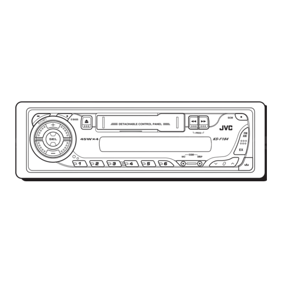
Cassette receiver
Hide thumbs
Also See for KS-F184:
- Instructions manual (18 pages) ,
- Installation & connection manual (2 pages)
Table of Contents
Advertisement
Quick Links
Download this manual
See also:
Instruction Manual
QQ
3 7 63 1515 0
SERVICE MANUAL
4
2005
MA181
TE
L 13942296513
1
PRECAUTION. . . . . . . . . . . . . . . . . . . . . . . . . . . . . . . . . . . . . . . . . . . . . . . . . . . . . . . . . . . . . . . . . . . . . . . . . 1-3
2
SPECIFIC SERVICE INSTRUCTIONS . . . . . . . . . . . . . . . . . . . . . . . . . . . . . . . . . . . . . . . . . . . . . . . . . . . . . . 1-4
3
DISASSEMBLY . . . . . . . . . . . . . . . . . . . . . . . . . . . . . . . . . . . . . . . . . . . . . . . . . . . . . . . . . . . . . . . . . . . . . . . 1-5
4
ADJUSTMENT . . . . . . . . . . . . . . . . . . . . . . . . . . . . . . . . . . . . . . . . . . . . . . . . . . . . . . . . . . . . . . . . . . . . . . . 1-13
5
TROUBLESHOOTING . . . . . . . . . . . . . . . . . . . . . . . . . . . . . . . . . . . . . . . . . . . . . . . . . . . . . . . . . . . . . . . . . 1-17
www
.
CASSETTE RECEIVER
KS-F184
TABLE OF CONTENTS
x
COPYRIGHT © 2005 Victor Company of Japan, Limited
http://www.xiaoyu163.com
2 9
8
Q Q
3
6 7
1 3
1 5
co
.
9 4
2 8
KS-F184
Area suffix
UI ---------------------------- India
0 5
8
2 9
9 4
2 8
m
No.MA181
9 9
9 9
2005/4
Advertisement
Table of Contents

Related Manuals for JVC KS-F184


Summary of Contents for JVC KS-F184
-
Page 1: Table Of Contents
3 7 63 1515 0 SERVICE MANUAL CASSETTE RECEIVER MA181 2005 KS-F184 KS-F184 Area suffix UI ---------------------------- India L 13942296513 TABLE OF CONTENTS PRECAUTION............... . . 1-3 SPECIFIC SERVICE INSTRUCTIONS . -
Page 2: Http://Www.xiaoyu163.Com
http://www.xiaoyu163.com 3 7 63 1515 0 SPECIFICATION AUDIO AMPLIFIER SECTION Maximum Power Output Front 45 W per channel Rear 45 W per channel 17 W per channel into 4 Ω, 40 Hz to 20 000 Hz at no more Continuous Power Output (RMS) Front than 0.8% total harmonic distortion. -
Page 3: Precaution
http://www.xiaoyu163.com SECTION 1 3 7 63 1515 0 PRECAUTION Safety Precautions Burrs formed during molding may be left over on some parts of the chassis. Therefore, pay attention to such burrs in the case of preforming repair of this system. L 13942296513 u163 (No.MA181)1-3... -
Page 4: Specific Service Instructions
http://www.xiaoyu163.com SECTION 2 3 7 63 1515 0 SPECIFIC SERVICE INSTRUCTIONS HOW TO IDENTIFY MODELS 2.1.1 NAME PLATE Discernment sign L 13942296513 u163 1-4 (No.MA181) http://www.xiaoyu163.com... -
Page 5: Disassembly
http://www.xiaoyu163.com SECTION 3 3 7 63 1515 0 DISASSEMBLY Main body 3.1.1 Removing the front panel assembly (See Fig.1) (1) Push the detach button and remove the front panel assem- bly. Front panel assembly Detach button Fig.1 3.1.2 Removing the bottom cover (See Fig.2) •... - Page 6 http://www.xiaoyu163.com 3.1.4 Removing the side panel 3 7 63 1515 0 (See Fig.4) • Prior to performing the following procedure, remove the front panel assembly. (1) Remove the screw B and two screws C attaching the side panel on the left side of the body, and remove the side pan- Side panel Fig.4 3.1.5 Removing the rear panel...
- Page 7 http://www.xiaoyu163.com 3.1.7 Removing the cassette mechanism assembly 3 7 63 1515 0 (See Fig.7) • Prior to performing the following procedure, remove the front panel assembly, bottom cover, front chassis assembly, side Cassette mechanism assembly panel, rear panel and main board. (1) Remove the four screws H attaching the cassette mecha- nism assembly from the top chassis.
- Page 8 http://www.xiaoyu163.com 3.1.10 Removing the mecha bracket 3 7 63 1515 0 (See Fig.10) • Prior to performing the following procedure, remove the front panel assembly, bottom cover, front chassis assembly, side Mecha bracket panel, rear panel, main board, cassette mechanism assembly, head amplifier board and relay board.
- Page 9 http://www.xiaoyu163.com Cassette mechanism assembly 3 7 63 1515 0 • Prior to performing the following procedures, remove the head 3.2.4 Removing the playback head amplifier board, the relay board and the mechanism bracket. (See Fig.2) • Prior to performing the following procedure, remove the direc- 3.2.1 Removing the direction switch board tion switch board and the FF / REW lever assembly.
- Page 10 http://www.xiaoyu163.com 3.2.6 Removing the cassette hanger / cassette holder 3 7 63 1515 0 Cassette holder (See Fig.3) Return link Joint i • Prior to performing the following procedure, remove the FF / Cassette hanger REW lever assembly. Eject lever (1) From the rear of the unit, bend the two tabs f outwards and disengage the two joints g in the direction of the arrow.
- Page 11 http://www.xiaoyu163.com 3.2.9 Removing the Flywheel (BF) and (BR) assembly 3 7 63 1515 0 3.2.10 Removing the reel base assembly (See Fig.4 and 5) (See Fig.5 and 6) • Prior to performing the following procedure, remove the cas- (1) Raise the part k of the reel base assembly slightly and re- sette hanger / cassette holder.
- Page 12 http://www.xiaoyu163.com 3.2.11 Removing the mute switch board (See Fig.8) 3 7 63 1515 0 Cassette mechanism assembly Rower switch (1) Unsolder the two wires l on the mute switch board on the back of the cassette mechanism assembly. Soldering l Motor assembly (2) Remove the screw H attaching the mute switch board.
-
Page 13: Adjustment
http://www.xiaoyu163.com SECTION 4 3 7 63 1515 0 ADJUSTMENT Adjustment method Test instruments required for adjustment (1) Digital oscilloscope (100MHz) (2) Frequency counter meter (3) Electric voltmeter (4) Wow & flutter meter (5) Test tapes VT724 : For DOLBY level measurement VT739 : For playback frequency measurement VT712 : For wow flutter &... - Page 14 http://www.xiaoyu163.com Information for using a car audio service jig 3 7 63 1515 0 (1) We're advancing efforts to make our extension cords common for all car audio products. Please use this type of extension cord as follows. (2) As a U-shape type top cover is employed, this type of extension cord is needed to check operation of the mechanism assembly after disassembly.
- Page 15 http://www.xiaoyu163.com Arrangement of Adjusting & Test points 3 7 63 1515 0 Cassette mechanism (Surface) Motor assembly Tape speed adjust Playback head Azimuth screw Head section view L 13942296513 Head azimuth screw Fixed screw Playback head Height adjusting screw a Height adjusting screw c Height adjusting screw b u163...
- Page 16 http://www.xiaoyu163.com 3 7 63 1515 0 Item Conditions Adjustment and Confirmation methods S.Values Adjust Head Head height adjustment Test tape: azimuth Adjust the azimuth directly. When you SCC-1659 adjustment adjust the height using a mirror tape, VT703 (10kHz) remove the cassette housing from the mechanism chassis.
-
Page 17: Troubleshooting
http://www.xiaoyu163.com SECTION 5 3 7 63 1515 0 TROUBLESHOOTING 16 PIN CORD DIAGRAM Black Green BL/WH Violet Blue Gray WH/BK Yellow White GN/BK VI/BK GY/BK 16 YL MEMORY 8 BK L 13942296513 7 RD 5 BL/WH REMOTE 4 WH 12 WH/BK 3 GN 11 GN/BK 2 VI... - Page 18 http://www.xiaoyu163.com 3 7 63 1515 0 L 13942296513 u163 Victor Company of Japan, Limited AV & MULTIMEDIA COMPANY CAR ELECTRONICS CATEGORY 10-1,1chome,Ohwatari-machi,Maebashi-city,371-8543,Japan (No.MA181) Printed in Japan http://www.xiaoyu163.com...
- Page 19 3 7 63 1515 0 SCHEMATIC DIAGRAMS CASSETTE RECEIVER KS-F184 CD-ROM No.SML200504 KS-F184 Area suffix UI ---------------------------- India L 13942296513 Contents Block diagram (For UI version) Standard schematic diagrams (For UI version) Block diagram (For UI3 version) Standard schematic diagrams (For UI3 version)
- Page 20 http://www.xiaoyu163.com 3 7 63 1515 0 Safety precaution Burrs formed during molding may be left over on some parts of the chassis. Therefore, pay attention to such burrs in the case of preforming repair of this system. L 13942296513 u163 http://www.xiaoyu163.com...
- Page 21 http://www.xiaoyu163.com 3 7 6 3 1 5 1 5 0 Block diagram (For UI version) Mechanism control board Relay board MAIN MOTOR HEAD MUTE SW TAPE/RADIO SW PROG.SW. SPEAKER LINE CP721 CONNECTOR REAR OUT CN721 CP981 CJ921 CJ901 Main amplifier section Head amplifier section LFO+,LFO- LRO+,LRO-...
- Page 22 http://www.xiaoyu163.com 3 7 6 3 1 5 1 5 0 Standard schematic diagrams (For UI version) Main amplifier section QAU0311-001 Q989 KRA102M-T QNB0100-002 ACC.MUTE Q972 KRA102M-T 1SS119-041 MUTE2 D973 CJ921 QNN0519-001 R163 4.7u R164 D161 R165 2.2K 1SS119-041 D261 R265 MUTE R757 1SS119-041...
- Page 23 http://www.xiaoyu163.com 3 7 6 3 1 5 1 5 0 Head amplifier section CJ901 QGA2002C1-05 IC901 UPC1228HA C203 C103 R204 R104 1 3 9 4 2 2 9 6 5 1 3 330k 330k 100p 100p CP722 QGA2002F1-06 C901 CP721 QGB1214K1-06S CP901 QGB1214K1-06S...
- Page 24 http://www.xiaoyu163.com 3 7 6 3 1 5 1 5 0 LCD & Key control section To CJ701 (SHEET 1) CP701 VMC0335-001 IC651 LC75823W 1 3 9 4 2 2 9 6 5 1 3 COM1 R654 COM2 1.5k COM3 D654 R657 C651 UDZS5.1B-X...
- Page 25 http://www.xiaoyu163.com 3 7 6 3 1 5 1 5 0 Block diagram (For UI3 version) Mechanism control board Relay board MAIN MOTOR HEAD MUTE SW TAPE/RADIO SW PROG.SW. SPEAKER LINE CP721 CONNECTOR REAR OUT CN902 CP981 J931 CJ901 Main amplifier section Head amplifier section LFO+,LFO- LRO+,LRO-...
- Page 26 http://www.xiaoyu163.com 3 7 6 3 1 5 1 5 0 Standard schematic diagrams (For UI3 version) Main amplifier section QAU0281-001 IC941 LA4743K C951 C952 0.22/50 C948 R142 QNB0100-002 R251 R151 TU.R R114 C947 R141 0.22/50 4.7U TU.L 2.7K R113 2.7K 1/50 C111 C119...
- Page 27 http://www.xiaoyu163.com 3 7 6 3 1 5 1 5 0 Head amplifier section CJ901 QGA2002C1-05 IC901 UPC1228HA C203 C103 R104 R204 1 3 9 4 2 2 9 6 5 1 3 330k 330k 100p 100p CP722 QGA2002F1-06 C901 CP721 QGB1214K1-06S CP901 QGB1214K1-06S...
- Page 28 http://www.xiaoyu163.com 3 7 6 3 1 5 1 5 0 LCD & Key control section To CJ701 (SHEET 1) CP701 VMC0335-001 IC651 PT6523LQ-L 1 3 9 4 2 2 9 6 5 1 3 COM1 R654 COM2 1.5k COM3 D654 R657 C651 UDZS5.1B-X...
- Page 29 http://www.xiaoyu163.com 3 7 63 1515 0 Printed circuit boards Main board (For UI version) CP981 L981 CP751 CJ921 C981 D981 CN901 C983 D771 C986 C132 C150 C931 C771 C133 C997 R771 C940 R721 C709 C996 C942 R941 IC981 C933 R722 C934 R992 C250...
- Page 30 http://www.xiaoyu163.com 3 7 63 1515 0 Main board (For UI3 version) C961 L961 R970 J931 D961 J751 C969 R136 R236 B106 CN901 C954 C953 C952 C951 R132 D931 R232 C112 D932 C941 B201 B109 B219 B202 B132 B221 B203 B280 C967 C982 R961...
- Page 31 http://www.xiaoyu163.com 3 7 63 1515 0 Switch board (Common) Forward side D601 D602 R654 D619 C651 C653 R635 R655 D603 C652 R602 S603 S606 S604 D617 PL603 PL601 D604 D616 D615 D607 D608 R606 D609 D610 D611 D612 R607 R608 D614 S605 S608...
- Page 32 http://www.xiaoyu163.com 3 7 63 1515 0 L 13942296513 u163 Victor Company of Japan, Limited AV & MULTIMEDIA COMPANY CAR ELECTRONICS CATEGORY 10-1,1chome,Ohwatari-machi,Maebashi-city,371-8543,Japan Printed in Japan (No.MA181SCH) http://www.xiaoyu163.com...
-
Page 33: Parts List
3 7 63 1515 0 PARTS LIST [ KS-F184 ] * All printed circuit boards and its assemblies are not available as service parts. Area suffix L 13942296513 UI ---------------------------- India - Contents - 3- 2 Exploded view of general assembly and parts list (Block No.M1) 3- 5 Cassette mechanism assembly and parts list (Block No.MP) - Page 34 http://www.xiaoyu163.com 3 7 63 1515 0 Exploded view of general assembly and parts list Block No. L 13942296513 Switch board u163 http://www.xiaoyu163.com...
- Page 35 http://www.xiaoyu163.com 3 7 63 1515 0 L 13942296513 u163 http://www.xiaoyu163.com...
- Page 36 http://www.xiaoyu163.com 3 7 63 1515 0 General Assembly Block No. [M][1][M][M] Symbol No. Part No. Part Name Description Local GE10043-012A TOP CHASSIS GE40135-001A EARTH PLATE GE30938-003A SIDE PANEL QYSDST2004ZA TAP SCREW M2 x 4mm(x2) QYSDST2604ZA TAP SCREW M2.6 x 4mm(x4) GE40235-001A SCREW (x2)
- Page 37 http://www.xiaoyu163.com 3 7 63 1515 0 Cassette mechanism assembly and parts list Block No. CDS-363SJ2 L 13942296513 u163 http://www.xiaoyu163.com...
- Page 38 1-0036-7073S WIRE(AL) X-0363-7006S MOTOR ASSY 1-0363-7001S MUTE SW 1-0036-7007-1S SLIDE SW 1-0363-7008S SLIDE SW PWB 1-0036-7034S POWER SW u163 1-0036-7089S 6P WIRE ASY(JVC 1-0036-7088S 5P WIRE ASY(JVC 2-1816-0032-E8S MYLAR WASHER(S) (x2) 2-1812-0030-D2S PSW-S (x3) 1-0036-5024S PSW(REEL) (x5) 2-1712-0050-16S E RING...
- Page 39 http://www.xiaoyu163.com 3 7 63 1515 0 Symbol No. Part No. Part Name Description Local 1-0363-7015S MUTE SWITCH BOARD 2-1331-7040-C2S SCREW S 2-1331-7060-C2S SCREW S 2-1382-0030-C2S SCREW B (x5) 2-1332-0040-C1S SCREW S 2-1032-0070-C2S SCREW (x2) 2-1032-0025-C2S SCREW (x2) 2-1012-0040-C2S SCREW 2-1012-0030-F2S SCREW 1-0138-5002S...
-
Page 40: Ao Y U163
http://www.xiaoyu163.com 3 7 63 1515 0 Grease point 1/2 Grease FL-942 SW-902 SW-522B FG-84M EP-56 Reverse side L 13942296513 u163 http://www.xiaoyu163.com... - Page 41 http://www.xiaoyu163.com 3 7 63 1515 0 Grease point 2/2 L 13942296513 u163 http://www.xiaoyu163.com...
-
Page 42: Electrical Parts List
http://www.xiaoyu163.com 3 7 63 1515 0 Electrical parts list Main board (KS-F184_UI) Symbol No. Part No. Part Name Description Local Block No. [0][1] C136 QFV61HJ-154Z MF CAPACITOR 0.15uF 50V J Symbol No. Part No. Part Name Description Local C137 QFV61HJ-154Z MF CAPACITOR... - Page 43 http://www.xiaoyu163.com 3 7 63 1515 0 Symbol No. Part No. Part Name Description Local Symbol No. Part No. Part Name Description Local QRE141J-512Y C RESISTOR 5.1kΩ 1/4W J QNB0100-002 CAR ANT JACK QRE141J-391Y C RESISTOR 390Ω 1/4W J QAU0311-001 TUNER QRE141J-512Y...
- Page 44 http://www.xiaoyu163.com 3 7 63 1515 0 Main board (KS-F184_UI3) Symbol No. Part No. Part Name Description Local Block No. [0][4] S602 NSW0124-001X TACT SW S603 NSW0124-001X TACT SW Symbol No. Part No. Part Name Description Local S604 NSW0124-001X TACT SW S605 NSW0124-001X...
- Page 45 http://www.xiaoyu163.com 3 7 63 1515 0 Symbol No. Part No. Part Name Description Local Symbol No. Part No. Part Name Description Local C118 QERF1HM-105Z E CAPACITOR 1uF 50V M NRS181J-152X MG RESISTOR 1.5kΩ 1/8W J C119 QERF1HM-105Z E CAPACITOR 1uF 50V M NRSA63J-101X MG RESISTOR...
- Page 46 http://www.xiaoyu163.com 3 7 63 1515 0 Symbol No. Part No. Part Name Description Local Symbol No. Part No. Part Name Description Local R963 NRSA63J-123X MG RESISTOR 12kΩ 1/16W J R636 NRSA02J-122X MG RESISTOR 1.2kΩ 1/10W J R966 NRSA63J-473X MG RESISTOR 47kΩ...
- Page 47 http://www.xiaoyu163.com 3 7 63 1515 0 <MEMO> L 13942296513 u163 3-15 http://www.xiaoyu163.com...
- Page 48 http://www.xiaoyu163.com 3 7 63 1515 0 Packing materials and accessories parts list Block No. A3 A4 L 13942296513 KIT: A8 A9 u163 3-16 http://www.xiaoyu163.com...
- Page 49 http://www.xiaoyu163.com 3 7 63 1515 0 Packing and Accessories Block No. [M][3][M][M] Symbol No. Part No. Part Name Description Local GE20137-003A MOUNTING SLEEVE GE20135-004A TRIM PLATE GET0308-001A INSTR BOOK GET0308-002A INSTALL MANUAL VKZ4027-202 PLUG NUT VKH4871-003 MOUNT BOLT VKZ4328-003 LOCK NUT QYWWS53A008ZA WASHER...
Need help?
Do you have a question about the KS-F184 and is the answer not in the manual?
Questions and answers