Table of Contents
Advertisement
Advertisement
Table of Contents

Related Manuals for Toyotomi DCT 100HSPi


Summary of Contents for Toyotomi DCT 100HSPi
- Page 1 MODEL: DCT 100HSPi-o DCT 140HSPi-o DCT 170HSPi-o...
- Page 2 Contents Part 1 General information Part 2 Indoor units Part 3 Outdoor units Part 4 Installation Part 5 Control Contents...
-
Page 3: Part 1 General Information
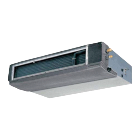
General Information Part 1 General Information General Information... - Page 4 Model Names of Indoor/ Outdoor Units 1. Model Names of Indoor/ Outdoor Units Model Names of Indoor Units: DCT 100HSPi, DCT 140HSPi, DCT 170HSPi Model Names of Outdoor Units: DCT 100HSPo, DCT 140HSPo, DCT 170HSPo 2. External Appearance Indoor units...
- Page 5 Features 4. Features The dimension is really more compact than the former type MHA series; 4.2 High-static pressure; 4.3 Multi-blowing outlets, 4.4 Indoor Unit can be installed in various ways to give you a creative space; 4.5 We adopt universal outdoor units for R410A refrigerant. General Information...
- Page 6 Indoor units Part 2 Indoor units High Static Pressure Type Indoor units...
- Page 7 High static pressure type High Static Pressure Type 8. Sound Lev 9. Exploded view 10. Static pressure Indoor units...
- Page 8 Features 1. Features 1.1 The new designed high static pressure duct adopt the body of new concealed duct DCT 100HSPi, DCT 140HSPi, DCT 170HSPi; the dimension is really more compact than the former type HSP series. 1.2 High-static pressure Blowing pressure of Indoor Unit can reach 150Pa. The air conditioner delivers cold wind to every indoor corner even the ceiling is super-high.
- Page 9 Dimensions 2.Dimensions 2.2. DCT 100HSPi 2.3. DCT 140HSPi, DCT 170HSPi Indoor units...
- Page 10 Service space 3. Service space Note: Above figure means minimum value. Please keep these value at least. Indoor units...
- Page 11 Piping diagrams 4. Piping Diagrams Remark: For DCT 100HSPo, DCT 140HSPo, check valve and auxiliary capillary is not included. Indoor units...
- Page 12 Wiring diagrams 5.4. DCT 100HSPi 2.3. DCT 140HSPi, DCT 170HSPi Indoor units...
- Page 13 Air velocity and temperature distributions 6. Air Velocity and Temperature Distributions Discharge angle 60 Airflow velocity Indoor units...
-
Page 14: Electric Characteristics
Electric characteristics DCT 100HSPi, DCT 140HSPi, DCT 170HSPi 7. Electric Characteristics Units Power supply Model Voltage Min. Voltage Max. Voltage MFA KW DCT 100HSPi 0.9125 DCT 140HSPi 2.8125 2,25 DCT 170HSPi 2.8125 350 2,25 Symbols: MCA: Min. Circuit Amps(A) MFA: Max. Fuse Amps(See note 5) -
Page 15: Sound Levels
Sound levels 8. Sound Levels CONCEALED DUCT TYPE Duct 1.0m Microphone DCT 100HSPi DCT 140HSPi, DCT 170HSPi Audibility limits of continuous white sound Audibility limits of continuous white sound Octave band center frequency Hz Octave band center frequency Hz Indoor units... - Page 16 Static pressure 10.Static pressure DCT 140HSPi, DCT 170HSPi DCT 100HSPi Indoor units...
- Page 17 Accessories 11. Accessories 11.1 Wild variety of optional accessories ---Including front clapboard, panel, canvas air passage, filter, etc. Canvas air passage Clapboard Panel 11.2 A long-life and high-efficiency filter 11.3 Way of air intake and inserting air filter ---Air intake can be positioned either at the back or below the unit. Similarly, the air filter also can be inserted either from the back or from the bottom of the unit.
-
Page 18: Outdoor Units
Outdoor units Outdoor Units 2. Service S 8. Exploded view 9. Troubleshooting Outdoor units... - Page 19 Dimensions 1.3. DCT 100HSPo 1.4. DCT 140HSPo, DCT 170HSPo Outdoor units...
-
Page 20: Service Space
Service space 2. Service Space DCT 170HSPo Obstacle (Wall or obstacle) Air inlet >30cm Fix with bolt Air inlet Maintain channel >60cm Air outlet Deep foundation Necessary width 600mm M10 bolt 4pieces per unit Outdoor units... - Page 21 Wiring diagrams 3.4. DCT 100HSPi 3. 5. DCT 140HSPi, DCT 170HSPi Outdoor units...
- Page 22 Electric characteristics 5. Electric Characteristics Units Compressor Model Voltage Min. Max. DCT 100HSPo 6.58 1.38 DCT 140HSPo 8.22 DCT 170HSPo 9.77 Symbols: MSC: Max. Starting Current RLA: Rated Locked Current OFM: Outdoor Fan Motor FLA: Full Load Amps. KW: Rate Motor Output Notes: 1.
-
Page 23: Operation Limits
Operation limits 6. Operation Limits Ensure the operating temperature is in allowable range. Cooling Heating With low ambient temp. cooling module Indoor temp.( C) Indoor temp.( C) Outdoor units... - Page 24 Sound levels 7. Sound levels Microphone Model Noise Level(dB(A)) 18000Btu/h 24000Btu/h 30000Btu/h 36000Btu/h 48000Btu/h 60000Btu/h Outdoor units...
-
Page 25: Troubleshooting
Troubleshooting 9. Troubleshooting 9.1 I Protection or Malfunction Operation Timer lamp Defrosting Auto lamp lamp recover Indoor temp. sensor abnormal × × Indoor heat exchanger sensor abnormal × × Outdoor heat exchanger sensor abnormal × × Outdoor abnormal EEPROM abnormal ×... - Page 26 Troubleshooting 9.2.1 Phase sequence error: Phase sequence error Change the order of two of the wires to power supply. Switch on the unit again. If the problem can not be solved, the outdoor PCB is defective 9.2.2 Overload of current Overload of current Check the current, normally The max.
- Page 27 Troubleshooting 9.2.3 Lack of phase Lack of phase Check the power supply, is it 3 phase, Check the connection between power supply and terminal, Outdoor PCB is defective Outdoor units...
- Page 28 Troubleshooting 9.2.4 Protection of pressure or temp. Protection of pressure or temp. Is it k1 or K2 open ? Is temp. protective switch K1 Is pressure protective switch Possible reason Possible reason 1. The wires is loose to K1 1. The wires is loose to 2.
- Page 29 Troubleshooting 9.2.5 Open-circuit and short-circuit trouble of T3 Is connection to connector of temp. sensor good? Repair connector Check the resistance of the temp. sensor according to Annex 1 Is it the resistance is normal? Indoor PCB is defective. Replace the sensor 9.2.6 Open-circuit and short-circuit trouble of T4 Is connection to connector of temp.
- Page 30 Troubleshooting 9.2.7 High temperature protection of condenser High temperature protection of condenser Check the resistance of the temp. sensor according to Annex 1, is it normal? Possible reason Replace the sensor 1. Air or other gas in the refrigerant. 2. Heat exchanger is dirty 3.
- Page 31 Troubleshooting 9.3 Troubles and Solutions If any the following abnormal conditions occur, turn off the power supply immediately. Please contact our dealer. TROUBLES Indicator lamps flash rapidly, after your disconnecting and connecting the unit, the situation is the same. Fuse or circuit breaker work frequently. Foreign matter or water has fallen into the unit.
- Page 32 Troubleshooting Temperature display disappear Symptom Checking items Cause Temperature Display does Check if the mode display on not light. the LCD is FAN ONLY temperature when the unit is on FAN ONLY mode. The Display Goes Off Symptom Checking items Cause indication Check...
-
Page 33: Installation Part
Installation Part 4 Installation Installation... - Page 34 Installation 1. Refrigerant pipe installation 1.1. Measure the necessary length of the connecting pipe, and make it by the following way. Connect the indoor unit at first, then the outdoor unit. Bend the tubing in proper way. Do not harm them. CAUTIONS: Daub the surfaces of the flare pipe and the joint nuts with frozen oil, and wrench it for 3~4 rounds With hands before fasten the flare nuts.
- Page 35 Installation 2.2. Vacuum dry procedure There are two methods of vacuum dry due to different construction environment: common vacuum dry, special vacuum dry. . Common vacuum dry procedure Vacuum dry (for the first time)---connect the all-purpose detector to the inlet of liquid pipe and gas pipe, and run the vacuum pump more than two hours (the vacuum pump should be below -755mmHg) -755mmHg after pumping 2 hours, moisture or leakage point will still exist in the pipe.
- Page 36 Installation entering and forming condensation water. . Vacuum dry for the second time······1h pumping Determinant: Pass if achieving below -755mmHg. If - . Vacuum placing test ······ 1h . Sketch map of special vacuum dry procedure 3. Additional charge 3.1. When the length of the one-way pipe is less than 5m, additional refrigerant charge after vacuuming is unnecessary.
- Page 37 Installation 4.1.3. Precautions The diameter of drainpipe should meet the drainage requirement at least. The drainpipe should be heat-insulated to prevent atomization. Drainpipe should be installed before installing indoor unit. After powering on, there is some water in water-receiver plate. Please check if the drain pump can operate correctly. All connection should be firm.
- Page 38 Installation 4.4 Convergent drainage 4.4.1. The number of indoor units should be as small as possible to prevent the traverse main pipe overlong. 4.4.2. Indoor unit with drain pump and indoor unit without drain pump should be in different drainage system. 4.4.3.
- Page 39 Installation 5. Insulation work 5.1 Insulation material and thickness 5.1.1. Insulation material in the high-pressure side, no less than 120 in the low-pressure side(For the cooling type machine, no requirements at the low-pressure side.) Example: Heat pump type----Heat-resistant Polyethylene foam (withstand above 120 ) Cooling only type---- Polyethylene foam (withstand above 100 ) 5.1.2.
- Page 40 Installation wrong right Gas pipe and liquid pipe Insulate the gas pipe Insulate the gas pipe and should (cooling only) liquid pipe For construction convenience, before laying pipes, use insulation material to insulate the pipes to be deal with, at the same time, at two ends of the pipe, remain some length not to be insulated, in order to be welded and check the leakage after laying the pipes.
- Page 41 Control Part 5 Control Control...
- Page 42 Control 1. Remote controller The below is R11HG/E remote controller. Control...
-
Page 43: Fan Button
Control Mode select button I/O Button Each time you push Push the button to start button, a mode is operation, push the selected in a sequence button again to stop that goes from AUTO, operation. COOL, DRY, HEAT (cooling only type without), FAN ONLY and back to AUTO. -
Page 44: Clock Button
Control After Sliding the cover, the button and function are as follows: Auto louver button Timer button Push this button to swing Push ON-TIME timer louver. Push the button button to set the ON timer. again to stop. Push OFF-TIME timer button to set the OFF timer. - Page 45 Control Control...
- Page 46 Controller 3.2 Wired Remote Controller 3.2.1 KJR-10B Name and functions of buttons on the wire controller 6. NAME AND FUNCTIONS OF BUTTONS ON WIRE CONTROLLER ON / OFF button Mode selection button Fan speed selection Timer on button Adjust button ▲ ECONOMICAL TIMER ON CLOCK...
- Page 47 Controller Name and function of LCD on the wire controller Mode select button (MODE): Press MODE button to select “COOL”, “DRY” , "HEAT", or "FAN ONLY" mode.(HEAT is invalid for COOL ONLY wire controller.) AUTO COOL HEAT Fan speed button (FAN SPEED) Press FAN SPEED to select fan speed from "AUTO", "LOW","...
- Page 48 Controller Installation Installation Notice: When the air conditioner needs the constant frequency wire Controller, be sure adding a Wire Joint with 5 terminal named A, B, C, D, E in indoor unit, and fixing a infrared emitter whose anode and cathode connecting with A and B near the receiver in the Indoor Unit Switch Board, then connecting the terminal +5v, GND, Run in the Switch Board to C,D,E respectively.
Need help?
Do you have a question about the DCT 100HSPi and is the answer not in the manual?
Questions and answers