Omron E5EC Datasheet
Digital temperature controller (48 × 96 mm)
Hide thumbs
Also See for E5EC:
- Datasheet (16 pages) ,
- Instruction manual (2 pages) ,
- User manual (440 pages)
Table of Contents
Advertisement
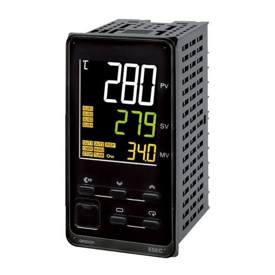
Digital Temperature Controller
E5EC
Large White PV Display That's Easier to Read.
Easy to Use, from Model Selection to
Setup and Operation.
A Complete Range of I/O Capacities,
Functions, and Performance.
Handles More Applications.
• A white LCD PV display with a height of approx. 18 mm
improves visibility.
• Easily connect the CX-Thermo (sold separately) through a
USB-Serial Conversion Cable (sold separately) to a Setup Tool port
on the top panel or on the front panel. The Digital Temperature
Controller receives the power required for setup from the computer
through the USB bus power source.
Settings can be made from CX-Thermo or the front panel of the Digital
Temperature Controller without wiring the power supply.
• High-speed sampling at 50 ms.
• Models with up to 4 auxiliary outputs, 6 event inputs, a transfer output,
and remote SP input added to the lineup. Complete selection of I/O
capacities.
• Short body with depth of only 60 mm.
Main I/O Functions
Sensor Input
• Thermocouple
• Pt
• Universal analog
current/voltage input
Indication Accuracy
• Thermocouple input:
±0.3% of PV
• Pt input: ±0.2% of PV
• Analog input: ±0.2% of FS
Sampling Period
• 50 ms
Event Inputs
• None
• 2
• 4
• 6
Remote SP Input
• None
• 1
This datasheet is provided as a guideline for selecting products.
Be sure to refer to the following manuals for application precautions and other information required for operation before attempting
to use the product.
E5CC/E5EC Digital Controllers User's Manual (Cat. No. H174)
E5CC/E5EC Digital Controllers Communications Manual (Cat. No. H175)
(48 × 96 mm)
E5EC
• PF (shift) Key
• Setup Tool port on front panel
• Temperature status display
• Simple programming
• Independent heating and
cooling PID control
• Changed parameter display
• Display brightness setting
48 × 96 mm
E5EC
Refer to Safety Precautions on page 30.
Three-level Display
PV, SV, and MV displayed
at the same time.
Control Output 1
• Relay output
• Voltage output (for driving SSR)
• Current output
Control Output 2
• Voltage output (for driving SSR)
• Relay output
• Current output
Auxiliary Outputs
• 4
Transfer Output
• None
• 1
4-digit displays
1
Advertisement
Table of Contents

Related Manuals for Omron E5EC


Summary of Contents for Omron E5EC
-
Page 1: Setup And Operation
This datasheet is provided as a guideline for selecting products. Be sure to refer to the following manuals for application precautions and other information required for operation before attempting to use the product. E5CC/E5EC Digital Controllers User’s Manual (Cat. No. H174) E5CC/E5EC Digital Controllers Communications Manual (Cat. No. H175) -
Page 2: Model Number Legend
E5EC Model Number Legend Input Output Fixed option Alarms Order code (48x96mm model) AC110-240V AC/DC24V Temperature Out1: 4 relays E5EC-RX4A5M-000 E5EC-RX4D5M-000 Relay Event Input 2, Communication E5EC-RX4A5M-009 E5EC-RX4D5M-009 &Analog Out2: 3-phase heater alarm none Event Input 4 E5EC-RX4A5M-010 E5EC-RX4D5M-010... -
Page 3: Heating And Cooling Control
Communications Conversion Cable CX-Thermo Support Software Model Model E58-CIFQ2-E EST2-2C-MV4 Note: Always use this product together with the E58-CIFQ2. Note: CX-Thermo version 4.4 or higher is required for the E5EC. Terminal Covers Model E53-COV24 Waterproof Packing Model Y92S-P9 Note: This Waterproof Packing is provided with the Digital Temperature Controller. -
Page 4: Specifications
E5EC Specifications Ratings A in model number: 100 to 240 VAC, 50/60 Hz Power supply voltage D in model number: 24 VAC, 50/60 Hz; 24 VDC Operating voltage range 85% to 110% of rated supply voltage Models with option selection of 000:6.6 VA max. at 100 to 240 VAC, and 4.1 VA max. at 24 VDC or Power consumption 2.3 W max. -
Page 5: Analog Input
E5EC Input Ranges ●Thermocouple/Platinum Resistance Thermometer (Universal inputs) Platinum resistance Infrared temperature Input type Thermocouple thermometer sensor 10 to 60 to 115 to 140 to Name Pt100 JPt100 PLII 70°C 120°C 165°C 260°C 2300 2300 1800 1800 1700 1700 1700... -
Page 6: Alarm Type
Always OFF when the upper-limit and lower-limit hysteresis overlaps. |H| ≥ |L| |H| < |L| |H| > |L| *6. Refer to the E5CC/E5EC Digital Controllers User's Manual (Cat. No. H174) H>0, L<0 for information on the operation of the standby sequence. |H| ≤ |L| *7. - Page 7 Non-volatile memory (number of writes: 1,000,000 times) Setup Tool CX-Thermo version 4.4 or higher E5EC top panel: An E58-CIFQ2 USB-Serial Conversion Cable is used to connect a USB port on the computer with the port on the top panel of the E5EC.*6 Setup Tool port...
-
Page 8: Communications Specifications
Windows 2000, XP, Vista, or 7 Applicable software CX-Thermo version 4.4 or higher Dielectric strength 1,000 VAC for 1 min Applicable models E5CC/E5EC and E5CB Vibration resistance 50 Hz, 98 m/s USB interface E54-CT1: Approx. 11.5 g, Conforms to USB Specification 1.1. - Page 9 E5EC External Connections E5EC E5EC-@@ 4 @ 5 M - @ @ @ Control output 1 (1) (2) (3) (4) (5) (6) Options Relay output ↑ 250 VAC, 5 A Terminal type Communications 4 event inputs Communications, 2 event 4 event inputs...
- Page 10 E5EC Nomenclature E5EC Top View Temperature unit No.1 display Setup Tool port No. 2 display on top panel No. 3 display Operation indicators Down key Shift (PF) key Up key Mode key Front Setup Tool port Level key Dimensions (Unit: mm)
- Page 11 When waterproofing is required, fit Watertight Packing on the backside of front panel. Keep the Port Cover on the front-panel Setup Tool port of the E5EC securely closed. The degree of protection when the Waterproof Packing is used is IP66. To maintain an IP66 degree of...
- Page 12 Thru-current (Io) vs. Output Voltage (Eo) (Reference Values) E54-CT3 Two, M3 (depth: 4) Maximum continuous heater current: 120 A (50/60 Hz) (Maximum continuous heater current for an OMRON Digital Temperature Controller is 50 A.) ± Number of windings: ± Ω...
-
Page 13: Setting Levels Diagram
Calibration Level parameter. Calibration Level Used to calibrate the E5EC. *1. To use a key procedure to move to Manual Control Level, set the Auto/Manual Select Addition parameter to ON and set the PF Setting parameter to a-m (Auto/ Manual). - Page 14 The value will appear in the display Display exceeds the display for the PV. range range. The PV is Refer to the E5CC/E5EC Digital exceeded displayed for the Controllers User’s Manual (Cat. No. range that is given on H174) for information on the...
- Page 15 E5EC Operation Parameters The related setting items in each level are described below. If you press the Mode Key at the last setting item, the display will return to the first setting item in the same level. Press the Key *2...
- Page 16 Event Input α "PV/SP (2)" Display Alarm 1 OFF Delay Assignment msp0 Assignment 1 0.65 alm4 Screen Selection (E5EC only) ev-2 tidu a2of alma odsl Integral/Derivative Integrated Alarm Event Input Alarm 2 OFF Delay MV Display Selection Time Unit...
-
Page 17: Safety Precautions
E5EC Safety Precautions Refer to Safety Precautions for All Digital Temperature Controllers. CAUTION Tighten the terminal screws to the rated torque of Do not touch the terminals while power is being between 0.43 and 0.58 N•m. supplied. Loose screws may occasionally result in fire. - Page 18 Use the specified communications cable. 5.8 mm or less). For open-wired connections, use stranded or Refer to the E5CC/E5EC Digital Controllers User’s Manual (Cat. solid copper wires with a gauge of AWG24 to AWG18 (equal to a No. H174) for information on the communications distances and crosssectional area of 0.205 to 0.823 mm...
-
Page 19: Measurement Accuracy
4. If the measurement accuracy is low, check to see if input shift has 2. Insert the E5EC into the mounting hole in the panel. been set correctly. 3. Push the adapter from the terminals up to the panel, and temporarily fasten the E5EC. -
Page 20: Precautions When Wiring
Unit, the positive and negative thermocouple input terminals of the Unit are short-circuited, and the ambient temperature is stable. Should the Unit malfunction during the guarantee period, OMRON shall repair the Unit or replace any parts of the Unit at the expense of OMRON. -
Page 21: Terms And Conditions Of Sale
Buyer indemnifies Omron against all related costs or expenses. rights of another party. 10. Force Majeure. Omron shall not be liable for any delay or failure in delivery 16. Property; Confidentiality. Any intellectual property in the Products is the exclu-... - Page 22 OMRON ELETRÔNICA DO BRASIL LTDA • HEAD OFFICE São Paulo, SP, Brasil • 55.11.2101.6300 • www.omron.com.br OMRON EUROpE B.V. • Wegalaan 67-69, NL-2132 JD, Hoofddorp, The Netherlands. • Tel: +31 (0) 23 568 13 00 • Fax: +31 (0) 23 568 13 88 • www.industrial.omron.eu Authorized Distributor: Automation Systems •...
Need help?
Do you have a question about the E5EC and is the answer not in the manual?
Questions and answers