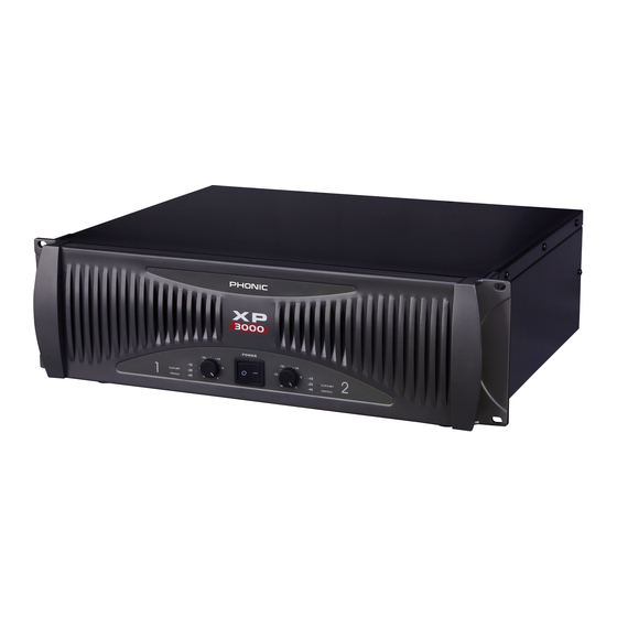
Phonic XP 600 User Manual
Power amplifier
Hide thumbs
Also See for XP 600:
- Service manual (32 pages) ,
- User manual (28 pages) ,
- User manual (13 pages)
Table of Contents
Advertisement
Quick Links
XP 600
XP 2000 XP 2100
XP 3000 XP 3100
POWER AMPLIFIER
XP 1000
- - 1 1 6 6
- - 1 1 4 4
N N O O R R M M A A L L
-
10
-6
60
CLIP/
- - 3 3 2 2
SUB
90
LIMIT
- - 2 2 0 0
- - 2 2 0 0
- - 2 2 0 0
- - 2 2 0 0
WOOFER
120
PROTECT
- - 4 4 0 0
- - 4 4 0 0
- - 4 4 0 0
- - 4 4 0 0
0
English
- - 1 1 6 6
- - 1 1 4 4
-
10
N N O O R R M M A A L L
6
- - 3 3 2 2
CLIP/
60
- - 2 2 0 0
- - 2 2 0 0
- - 2 2 0 0
- - 2 2 0 0
SUB
LIMIT
90
WOOFER
120
- - 4 4 0 0
- - 4 4 0 0
- - 4 4 0 0
- - 4 4 0 0
PROTECT
C C
0
POWER
XP 3100
Advertisement
Table of Contents

Subscribe to Our Youtube Channel
Summary of Contents for Phonic XP 600
- Page 1 XP 600 XP 1000 XP 2000 XP 2100 XP 3000 XP 3100 POWER AMPLIFIER - - 1 1 6 6 - - 1 1 4 4 - - 1 1 6 6 - - 1 1 4 4 N N O O R R M M A A L L...
-
Page 2: Important Safety Instructions
IMPORTANT SAFETY INSTRUCTIONS The apparatus shall not be exposed to dripping or splashing and that no objects filled with liquids, such as vases, shall be placed on the apparatus. The MAINS plug is used as the disconnect device, the disconnect device shall remain readily operable. -
Page 3: Table Of Contents
TABLE OF CONTENTS INTRODUCTION...........................4 FEATURES..........................4 INSTALLATION.........................5 FRONT PANEL DESCRIPTION....................6 REAR PANEL DESCRIPTION......................8 DIMENSIONS.........................10 SPECIFICATIONS........................11 SYSTEM BLOCK DIAGRAM......................13 APPENDIX..........................14 SERVICE REQUEST FORM.......................15 Phonic reserves the right to improve or alter any information supplied within this document without prior notice. V1.4 10/21. 2005... -
Page 4: Introduction
Fast Recovery design for lower distortion if clipping occurs Active balanced inputs for low noise XLR/TRS connectors for maximum input flexibility Speakon and 5-way binding post speaker outputs 2 ventilation variable speed fans Very rugged housing fits a standard 19” rack XP 600/1000/2000/2100/3000/3100... -
Page 5: Installation
The amplifier built-in XLR and TRS connectors can be wired similarly for balanced or un- balanced, floating or ground-referenced sources. The output connector is a binding post with Speakon which provides an easy connection when using banana plugs, spade lugs or bare wires. XP 600/1000/2000/2100/3000/3100... -
Page 6: Front Panel Description
LED will light for a few seconds, and then go been put in to the channel. The threshold for the indi- out, indicating that the relay has closed, connecting cator is -40dB, above that, noise will trigger the LED to the speakers to the amplifier. light. XP 600/1000/2000/2100/3000/3100... - Page 7 When the power is on, the PHONIC logo at the top of the front panel will light up in green. should verify that all system operations are normal before turning on the amplifier.
-
Page 8: Rear Panel Description
Spade lugs and bare wires should both be screwed down tightly to avoid a short circuit. The Speakon connector for channel 1 includes channel 1, channel 2 and bridged mono pin connecting points. A pin out information could be foundbeside the Speakon connector. XP 600/1000/2000/2100/3000/3100... - Page 9 This switch can activate a 30Hz or 50Hz high pass filter, which will roll off signals below either 30 Hz or 50 Hz. This improves sub bass performance by limiting sub bass cone motion. It will make more power available for the speakers’ rated frequency range. XP 600/1000/2000/2100/3000/3100...
-
Page 10: Dimensions
DIMENSIONS XP2000/2100/3000/3100 442.4/17.42 482.6/19 XP600/1000 442.4/17.42 482.6/19 Measurements are shown in mm/inch. XP 600/1000/2000/2100/3000/3100... -
Page 11: Specifications
Cooling Connectors (each channel) Input: XLR & 1/4" TRS jacks Output: Speakon & binding posts Pow er: Amber Phonic logo; Parallel: Green backlight icon; Indicators Bridged: Red backlight icon CLIP/LIM: Red LED; PROTECT: Yellow LED Green LED for -10dB, -20dB and -40dB Signal Lights CH1 &... - Page 12 SPECIFICATIONS XP 600 XP 1000 XP 2000 / XP2100 XP 3000 / XP 3100 Short circuit, thermal, subsonic, RF protection, Output DC offset, Heatsink and transformer over-heat protection, Power on/off muting, Amplifier Protection Soft start power on 32x (30dB) 40x (32dB)
-
Page 13: System Block Diagram
SYSTEM BLOCK DIAGRAMS XP 600/1000/2000/2100/3000/3100... -
Page 14: Appendix
Phonic, at its option, shall repair or replace the defective unit covered by this warranty. Please retain the dated sales receipt as evidence of the date of purchase.


Need help?
Do you have a question about the XP 600 and is the answer not in the manual?
Questions and answers