Tennant 800 Operator's Manual
Tennant 800 scrubber dryer operator manual
Hide thumbs
Also See for 800:
- Service manual (402 pages) ,
- Operator's manual (100 pages) ,
- Instruction bulletin (4 pages)
Table of Contents

Related Manuals for Tennant 800


Summary of Contents for Tennant 800
- Page 1 TENNANT 800 SCRUBBER DRYER OPERATOR MANUAL Clemas & Co. Unit 5 Ashchurch Business Centre, Alexandra Way, Tewkesbury, Gloucestershire, GL20 8NB. Tel: 01684 850777 Fax: 01684 850707 Email: info@clemas.co.uk Web: www.clemas.co.uk...
-
Page 2: Safety Precautions
- - use cardboard to locate leaking - - unless trained and authorized. hydraulic fluid under pressure. - - unless operator manual is read and - - use tennant supplied or approved understood. replacement parts. - - if it is not in proper operating condition. - Page 3 SAFETY PRECAUTIONS The following safety labels are mounted on the machine in the locations indicated. If these or any label becomes damaged or illegible, install a new label in its place. EMISSIONS LABEL - - LOCATED ON THE NOISE LABEL - - LOCATED ON THE FRONT FRONT PANEL OF THE OPERATOR PANEL OF THE OPERATOR COMPARTMENT.
-
Page 4: Operation
OPERATION OPERATION OPERATOR RESPONSIBILITY - The operator’s responsibility is to take care of the daily maintenance and checkups of the machine to keep it in good working condition. The operator must inform the service mechanic or supervisor when the required maintenance intervals occur as stated in the MAINTENANCE section of this manual. - Page 5 We recommend taking advantage of a regularly scheduled service contract from your TENNANT representative. - Order parts and supplies directly from your authorized TENNANT representative. Use the parts manual provided when ordering parts. 800D 330149 (5- -04) Home...
-
Page 6: Machine Components
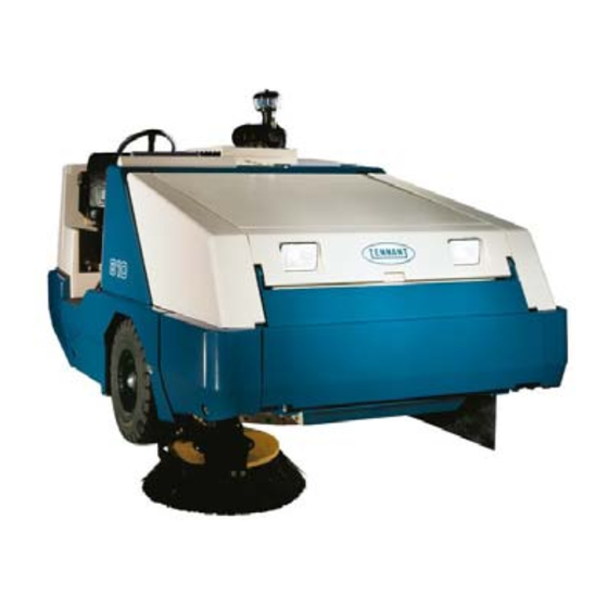
OPERATION MACHINE COMPONENTS 07623 A. Operator Seat B. Steering Wheel C. Engine Cover D. Engine Side Door E. Main Brush Access Door F. Hopper Cover G. Side Brush H. Instrument Panel Hopper Door J. Air Filter Assembly 800D 330149 (6- -02) Home Find... -
Page 7: Control Panel Symbols
OPERATION CONTROL PANEL SYMBOLS These symbols identify controls and displays on the machine: Engine Oil Pressure Hopper Temperature -- Thermo Sentry Engine Water Temperature Main Brush Shut Down Side Brush Down Pressure Light Filter Clogged Side Brush Down Pressure Heavy Hopper Door Closed Side Brush Down and On Fuel... - Page 8 OPERATION Circuit Breaker 2 Circuit Breaker 9 Circuit Breaker 3 Parking Brake Circuit Breaker 4 Glow Plugs (Preheat) Circuit Breaker 5 Hydraulic Filter Clogged Circuit Breaker 6 Engine Speed (For machines below serial number 006009) Idle (For machines serial number 006009 and above) Fast (For machines serial number 006009 and above) 800D 330149 (5- -04) Home...
-
Page 9: Controls And Instruments
OPERATION CONTROLS AND INSTRUMENTS Earlier Versions 351082 800D 330149 (5- -04) Home Find... Go To.. - Page 10 OPERATION A. Directional Pedal B. Brake Pedal C. Parking Brake Lever D. Side Brush Switch E. Side Brush Down Pressure Knob F. Hopper Door Lever G. Hopper Rollout Lever H. Hopper Lift Lever Horn Button J. Charging System Light K. Engine Oil Pressure Light L.
-
Page 11: Operation Of Controls
OPERATION OPERATION OF CONTROLS DIRECTIONAL PEDAL The directional pedal controls direction of travel and the propelling speed of the machine. You change the speed of the machine with the pressure of your foot; the harder you press the faster the machine travels. Forward: Press the top of the directional pedal with the toe of your foot. -
Page 12: Brake Pedal
OPERATION The toe angle of the directional pedal is adjustable. Remove the clevis pin, move the top of the pedal to the angle needed, and put the clevis pin through the adjustment holes. 08470 BRAKE PEDAL The brake pedal stops the machine. Stop: Take your foot off the directional pedal and let it return to the neutral position. -
Page 13: Side Brush Switch
OPERATION SIDE BRUSH SWITCH The right side brush switch controls the right side brush position and rotation. The optional left side brush switch controls the optional left side brush position and rotation. Down and On: Press the top of the switch into the On/Down position. -
Page 14: Hopper Door Lever
OPERATION HOPPER DOOR LEVER The hopper door lever opens and closes the hopper door. Close the hopper door when emptying the hopper to control debris and dust. Open: Pull and hold the hopper door lever in the Open position. 08474 Hold: Release the hopper door lever into the middle position. -
Page 15: Hopper Rollout Lever
OPERATION HOPPER ROLLOUT LEVER The hopper rollout lever moves the hopper in and out. Out: Pull and hold the hopper rollout lever in the Out position. 08477 Hold: Release the hopper rollout lever into the middle position. 08478 In: Push and hold the hopper rollout lever in the In position. -
Page 16: Hopper Lift Lever
OPERATION HOPPER LIFT LEVER The hopper lift lever raises and lowers the hopper. Raise: Pull and hold the hopper lift lever in the Up position. WARNING: Raised hopper may fall. Engage hopper support bar. 08480 Hold: Release the hopper lift lever up and into the middle position. -
Page 17: Charging System Light
OPERATION CHARGING SYSTEM LIGHT The charging system light comes on when the existing voltage potential of the battery is not within normal range (10 to 14 Volts). Stop operating the machine. Locate the problem and have it corrected. 07757 ENGINE OIL PRESSURE LIGHT The engine oil pressure light comes on when the engine oil pressure falls below 40 kPa (5 psi). -
Page 18: Main Brush Shut Down Light
OPERATION HOPPER TEMPERATURE LIGHT - - THERMO SENTRY The hopper temperature light comes on when there is too much heat in the hopper, possibly from a fire. The Thermo Sentry will stop the vacuum fan. The Thermo Sentry has to be reset manually, see THERMO SENTRY in MAINTENANCE. -
Page 19: Hopper Door Light (Option)
OPERATION HOPPER DOOR LIGHT (OPTION) The hopper door light comes on when the hopper door is open. Make sure the hopper door is closed and the hopper door light is off, before sweeping with the machine. 07763 FUEL LEVEL GAUGE The fuel level gauge indicates how much fuel is in the fuel tank with a segmented LED light. -
Page 20: Hazard Light Switch (Option)
OPERATION HAZARD LIGHT SWITCH (OPTION) The hazard light switch powers on and off the hazard light. On: Press the hazard light switch. The indicator light above the switch will come on. Off: Press the hazard light switch. The indicator light above the switch will go off. 07766 OPERATING LIGHTS SWITCH The operating lights switch powers on and off the... -
Page 21: Filter Shaker Switch
OPERATION FILTER SHAKER SWITCH The filter shaker switch starts the hopper dust filter shaker. The shaker automatically operates for 40 seconds. Start: Press the filter shaker switch. The indicator light will remain on while the filter shaker is operating. Stop: Press the filter shaker switch again IF wanting to stop the filter shaker during the 40 second shaking cycle. -
Page 22: Engine Speed Switch
OPERATION ENGINE SPEED SWITCH (For machines below serial number 006009) The engine speed switch controls engine governed speed. The three indicator lights above the switch show the engine speed; Start, Idle, or Fast. Start: The engine will automatically start in the Start speed. -
Page 23: Throttle Lever
OPERATION THROTTLE LEVER (For machines serial number 006009 and above) The throttle lever controls the engine speed. Fast: Pull the lever into the Fast position. This speed is for sweeping. 08456 Idle: Push the lever into the Idle position. This speed is for idling. -
Page 24: Ignition Switch
OPERATION IGNITION SWITCH The ignition switch starts and stops the engine with a key. Turn the key counter--clockwise. The glow plug light will come on. When the glow plug light goes out (5 to 15 seconds) the engine is ready to start. Start: Turn the key all the way clockwise. -
Page 25: Main Brush Switch
OPERATION MAIN BRUSH SWITCH The main brush switch controls the main brush position and rotation. Main Brush Down and Normal Speed: Press the front Normal position of the switch. Main Brush Up and Off: Place the switch in the middle Off position. Main Brush Down and II Speed: Press the rear II Speedt position of the switch. -
Page 26: Steering Wheel Tilt Lever
OPERATION STEERING WHEEL The steering wheel controls the machine’s direction. The machine is very responsive to the steering wheel movements. Left: Turn the steering wheel to the left. Right: Turn the steering wheel to the right. 08484 STEERING WHEEL TILT LEVER The steering wheel tilt lever controls the angle of the steering wheel. -
Page 27: Circuit Breakers
OPERATION CIRCUIT BREAKERS The circuit breakers are resetable electrical circuit protection devices. Their design stops the flow of current in the event of a circuit overload. Once a circuit breaker is tripped, it must be reset manually. Press the reset button after the breaker has cooled down. -
Page 28: Main Brush Down Pressure Knob
OPERATION MAIN BRUSH DOWN PRESSURE KNOB The main brush down pressure knob changes the main brush contact with the sweeping surface. Increase Pressure: Turn the main brush down pressure knob counter-clockwise. Decrease Pressure: Turn the main brush down pressure knob clockwise. LATCHES The side doors, rear door, engine cover, and hopper cover are secured with latches. -
Page 29: Operator Seat
OPERATION OPERATOR SEAT The operator seat has two adjustments. The adjustments are for the front to rear seat position and ride stiffness. The seat front-to-rear position is adjusted by the seat position lever. Adjust: Push the lever forward, slide the seat backward or forward to the desired position and release the lever. -
Page 30: Hopper Support Bar
OPERATION HOPPER SUPPORT BAR The hopper support bar is located on the operator’s side of the hopper. The hopper support bar holds the hopper in the raised position to allow work under the hopper. DO NOT rely on the machine hydraulic system to keep the hopper raised. -
Page 31: Fan Speed Switch (Option)
OPERATION FAN SPEED SWITCH (OPTION) The fan speed switch controls the speed of the fan in the optional cab. The pressurizer can be set at three different speeds and into the off setting. The HIGH fan speed switch is located on the roof of the optional cab. -
Page 32: How The Machine Works
OPERATION HOW THE MACHINE WORKS The steering wheel controls the direction of machine travel. The directional pedal controls the speed and forward/reverse direction. The brake pedal slows and stops the machine. The side brush sweeps debris into the path of the main brush. -
Page 33: Starting The Machine
OPERATION STARTING THE MACHINE 1. You must be in the operator’s seat with the directional pedal in neutral, and your foot on the brake pedal or with the parking brake set. FOR SAFETY: When starting machine, keep foot on brake and directional pedal in neutral. - Page 34 OPERATION 4. Turn the ignition switch key clockwise until the engine starts. NOTE: Do not operate the starter motor for more than 10 seconds at a time or after the engine has started. Allow the starter to cool between starting attempt or damage to the starter motor may occur.
- Page 35 OPERATION 8. Move the throttle lever to the Fast position. (For machines serial number 006009 and above) 08456 9. Drive the machine to the area to be swept. 351081 800D 330149 (5- -04) Home Find... Go To..
-
Page 36: Sweeping And Brush Information
OPERATION SWEEPING AND BRUSH INFORMATION Pick up oversized debris before sweeping. Flatten or remove bulky cartons from aisles before sweeping. Pick up pieces of wire, twine, string, etc., which could become entangled in brush or brush plugs. Plan the sweeping in advance. Try to arrange long runs with minimum stopping and starting. - Page 37 OPERATION Crinkle Wire 8-double Row Main Brush -- The stiff wire bristles cut through compacted grime, hard to sweep dirt, and dirt mixed with oil, grease, or mud. This brush is recommended for foundry sweeping where heat may melt synthetic bristles. This brush has good hopper loading ability, but is not recommended for dusty applications.
- Page 38 OPERATION SWEEPING 1. Select Fast engine speed. (For machines below serial number 006009) 07772 2. Move the throttle lever to the Fast position. (For machines serial number 006009 and above) 08456 3. The hopper door has to be closed during sweeping.
- Page 39 OPERATION 4. Place the main brush switch in the Normal or II Speed position. 5. Push the top of the side brush switch into the On/Down position. 6. Press the vacuum fan switch to start the vacuum. 7. Sweep as needed. 07769 800D 330149 (5- -04) Home...
-
Page 40: Stop Sweeping
OPERATION STOP SWEEPING 1. Push the bottom of the side brush switch into the Off/Up position. 2. Place the main brush switch in the middle Off position. 3. Press the filter shaker switch to shake the hopper dust filter. 07767 800D 330149 (12- -99) Home Find... -
Page 41: Emptying The Hopper
OPERATION EMPTYING THE HOPPER 1. Slowly drive the machine to the debris site or debris container. 351081 2. Pull and hold the hopper lift lever in the Up position and raise the hopper to the desired height. FOR SAFETY: When using machine, make sure adequate clearance is available before raising hopper. - Page 42 OPERATION 7. Pull and hold the hopper door lever into the Open position. 8. Raise the hopper enough and/or close the hopper door to clear the top of the debris container. 9. Slowly back the machine away from the debris site or debris container. FOR SAFETY: When using machine, move machine with care when hopper is raised.
-
Page 43: Stop The Machine
OPERATION STOP THE MACHINE 1. Stop sweeping. 2. Take your foot off the directional pedal. Step on the brake pedal. 08471 3. Select the Idle position with the engine speed switch. (For machines below serial number 006009) 07771 4. Move the throttle lever to the Idle position. (For machines serial number 006009 and above) 08457... - Page 44 OPERATION 5. Set the machine parking brake. 6. Turn the ignition switch key counter-clockwise to stop the engine. Remove the switch key. FOR SAFETY: Before leaving or servicing machine; stop on level surface, set parking brake, turn off machine and remove key. 800D 330149 (5- -04) Home Find...
-
Page 45: Post-Operation Checklist
OPERATION POST-OPERATION CHECKLIST - Check the engine oil level. - Check the engine coolant level. - Check the windshield washer fluid level (when applicable). - Check the radiator and hydraulic cooler fins for debris. - Check the hydraulic fluid level - Check the air filter indicator. -
Page 46: Engaging Hopper Support Bar
OPERATION ENGAGING HOPPER SUPPORT BAR 1. Set the machine parking brake. 2. Start the engine. 3. Raise the hopper all the way up. 08480 800D 330149 (12- -99) Home Find... Go To.. - Page 47 OPERATION 4. Remove the support bar from the storage clip. WARNING: Raised hopper may fall. Engage hopper support bar. 08589 5. Slowly lower the hopper so the support bar rests on the bar stop on the machine frame. WARNING: Lift arm pinch point. Stay clear of hopper lift arms.
-
Page 48: Disengaging Hopper Support Bar
OPERATION DISENGAGING HOPPER SUPPORT BAR 1. Start the engine. 2. Raise the hopper slightly to release the hopper support bar. 08480 3. Put the hopper support bar in the storage clip. WARNING: Lift arm pinch point. Stay clear of hopper lift arms. 08590 800D 330149 (12- -99) Home... -
Page 49: Operation On Inclines
OPERATION 4. Lower the hopper. 08482 5. Shut the engine off. OPERATION ON INCLINES Drive the machine slowly on inclines. Use the brake pedal to control machine speed on descending inclines. The maximum rated incline is 8.5_. FOR SAFETY: When using machine, move machine with care when hopper is raised. -
Page 50: Vacuum Wand
OPERATION OPTIONS VACUUM WAND The vacuum wand uses the machine’s vacuum system. The vacuum hose and wand allow pick-up of debris that is out of reach of the machine. 1. Stop the machine within reach of the area to be vacuumed and set the machine parking brake. - Page 51 OPERATION 4. Turn off and lift the side brush(es) by placing the bottom of the switch(es) into the Off/Up position. 5. Open the forward hopper access door and engage the lift arm. 6. Remove the vacuum plug from the vacuum adaptor tube in front of the hopper.
- Page 52 OPERATION 9. Close the vacuum door by sliding the vacuum door lever down and to the left into the locked position. 10.Turn on the vacuum fan by pressing the vacuum fan switch. The indicator light above the switch will go on. 07769 11.
- Page 53 OPERATION 13.Open the vacuum door by sliding the vacuum door lever to the right and up from the locked position. 14.Disconnect the vacuum hose from the vacuum adaptor tube in front of the hopper. 15.Disassemble the vacuum hose assembly and place back onto the hopper in the mounting clips.
-
Page 54: Regenerative Filter System (Rfs)
OPERATION REGENERATIVE FILTER SYSTEM (RFS) The Regenerative Filter System (RFS) is an option that alternately turns on the filter shaker motors when the filters need cleaning because of a build--up of dust or debris. Normally the RFS does not require the operator to stop the machine to shake the filters during sweeping operation (except in extreme and severe dust environments). -
Page 55: Machine Troubleshooting
Vacuum hose damaged Replace vacuum hose Vacuum fan seal (vacuum fan inlet Replace seal bracket) damaged Vacuum fan failure Contact TENNANT service personnel Hopper door partially or Open the hopper door completely closed Thermo Sentry tripped Reset Thermo Sentry... - Page 56 OPERATION 800D 330149 (5- -04) Home Find... Go To..
- Page 57 MAINTENANCE MAINTENANCE 07623 MAINTENANCE CHART NOTE: Check procedures indicted (H) after the first 50-hours of operation. No. of Lubricant/ Service Fluid Interval Description Procedure Points Check indicator Daily Engine air filter Empty dust cap Engine crankcase Check oil level Brush compartment skirts Check for damage, wear, and adjustment Hopper lip skirts...
- Page 58 5W30 (For machines serial number 006009 and above) diesel rating above CD grade only HYDO Tennant Company or approved hydraulic fluid . . . Special lubricant, Lubriplate EMB grease (TENNANT part no. 01433--1) . . . Water and permanent-type ethylene glycol anti-freeze, --34_ C (--30_ F) 800D 330149 (5- -04) Home Find...
- Page 59 MAINTENANCE LUBRICATION ENGINE (For machines below serial number 006009) Check the engine oil level daily. Change the engine oil and oil filter after the first 50 hours of machine operation, and then every 100 hours of operation. Use 10W30 engine oil with a diesel rating above CD grade only.
-
Page 60: Rear Wheel Support
The rear wheel support pivots the rear wheel. The support has one grease fitting for the bearings. The rear wheel support bearings must be lubricated every 200 hours of operation. Use Lubriplate EMB grease (TENNANT part no. 01433--1). FRONT WHEEL BEARINGS 08451... -
Page 61: Hydraulic Fluid Reservoir
Damage to the machine hydraulic system may result. Drain and refill the hydraulic fluid reservoir with new hydraulic fluid every 800 hours of operation. The hydraulic fluid filter is located in the engine compartment. Replace the filter element every 800 hours of operation. -
Page 62: Hydraulic Fluid
The quality and condition of the hydraulic fluid play a very important role in how well the machine operates. TENNANT’s hydraulic fluid is specially selected to meet the needs of TENNANT machines. TENNANT’s hydraulic fluids provide a longer life for the hydraulic components. There are two fluids available for different temperature ranges: TENNANT part no. -
Page 63: Hydraulic Hoses
MAINTENANCE HYDRAULIC HOSES Check the hydraulic hoses every 800 hours of operation for wear or damage. Fluid escaping at high pressure from a very small hole can be almost invisible, and can cause serious injuries. See a doctor at once if injury results from escaping hydraulic fluid. -
Page 64: Cooling System
MAINTENANCE ENGINE COOLING SYSTEM Check the radiator coolant every 100 hours of operation. Use clean water mixed with a permanent-type, ethylene glycol antifreeze to a --34_ C (--30_ F) rating. The coolant level should be 25 to 50 mm (1 to 2 in) below the filler opening. FOR SAFETY: When servicing machine, avoid contact with hot engine coolant. -
Page 65: Air Filter Indicator
MAINTENANCE AIR FILTER INDICATOR The air filter indicator shows when to replace the air filter element. Check the indicator daily. The indicator’s red line will move as the air filter element fills with dirt. Do not replace the air filter element until the red line reaches 5 kPa (20 in H O) and the ”SERVICE WHEN... -
Page 66: Belts And Chains
The battery is located in the left -- front of the engine compartment. After the first 50 hours of operation, and every 800 hours after that, clean and tighten the battery connections. BELTS AND CHAINS ENGINE BELT The engine fan belt is driven by the engine crankshaft pulley and drives the alternator pulley. -
Page 67: Air Conditioning Belt (Option)
MAINTENANCE AIR CONDITIONING BELT (OPTION) The air conditioning belt drives the compressor. The belt deflection should be 4 to 7 mm (0.025 to 0.25 in) when a force of (5 lbs) is applied at belt midpoint. Check and adjust the belt tension every 100 hours of operation. -
Page 68: Debris Hopper
MAINTENANCE DEBRIS HOPPER HOPPER DUST FILTER The dust filters filter the air pulled up from the hopper. The dust filters are equipped with a shaker to remove the accumulated dust particles. The dust filters shaker is operated by the filter shaker switch. - Page 69 MAINTENANCE 4. Remove the four retaining screws from the filter shaker frame. 5. Pull the filter shaker frame out of the hopper. 6. Carefully turn over the shaker frame and element. 08591 7. Loosen the four filter retaining screws from the shaker frame.
-
Page 70: Thermo Sentry
MAINTENANCE THERMO SENTRY The Thermo Sentry senses the temperature of the air pulled up from the hopper. If there is a fire in the hopper, the Thermo Sentry stops the vacuum fan and cuts off the air flow. The Thermo Sentry is located on the vacuum fan housing. -
Page 71: To Check And Adjust Main Brush Pattern
MAINTENANCE 4. Unlatch and remove the brush idler plate. 08487 5. Grasp the main brush; pull it off the brush drive plug and out of the main brush compartment. 6. Put the new or rotated end-for-end main brush on the floor next to the access door. 7. - Page 72 MAINTENANCE 3. Start the main brush. 4. Lower the main brush for 15 to 20 seconds while keeping a foot on the brakes to keep the machine from moving. This will lower the rotating main brush. NOTE: If chalk or other material is not available, allow the brushes to spin on the floor for two minutes.
- Page 73 MAINTENANCE If the main brush pattern is tapered, more than 15 mm (0.5 in) on one end than the other, adjust the taper at the drive end of the brush. 00601 A. Loosen the brush drive end plate mounting bolts. 08450 B.
-
Page 74: To Replace Side Brush
MAINTENANCE SIDE BRUSH The side brush sweeps debris along edges into the path of the main brush. Check the brush daily for wear or damage. Remove any string or wire found tangled on the side brush or side brush drive hub. Check the side brush pattern daily.The side brush bristles should contact the floor in a 10 o’clock to 3 o’clock pattern when the brush is in motion. -
Page 75: Skirts And Seals
MAINTENANCE SKIRTS AND SEALS HOPPER LIP SKIRTS The hopper lip skirts are located on the bottom rear of the hopper. The skirts float over debris and help deflect that debris into the hopper. The top skirt is segmented. Check the hopper lip skirts for wear or damage daily. -
Page 76: Brush Door Seals
MAINTENANCE BRUSH DOOR SEALS The brush door seals are located on both main brush doors and on corresponding portions of the main frame. Check the seals for wear or damage every 100 hours of operation. 08495 HOPPER SEALS The hopper seals are located on the top and side portions of the machine frame that contact the hopper. -
Page 77: Hopper Side Skirt
MAINTENANCE HOPPER SIDE SKIRT The hopper side skirt is located on the left side of the hopper. Check the hopper side skirt for wear or damage daily. 08492 HOPPER DUST SEAL The hopper dust seal is located inside the hopper. It seals the hopper filter compartment. -
Page 78: Brakes And Tires
MAINTENANCE BRAKES AND TIRES SERVICE BRAKES The hydraulic service brakes are located on the front wheels. The master brake cylinder is located on the fire wall. Check the master brake cylinder fluid level every 400 hours of operation. 08501 PARKING BRAKE Adjust the parking brake whenever it becomes very easy to set, when the machine rolls after setting it, and after every 200 hours of operation. -
Page 79: Front Wheel
FRONT WHEEL Torque the front wheel nuts twice in the pattern shown to 163 to 176 Nm (120 to 130 ft lb) after the first 50-hours of operation, and every 800 hours there after. REAR WHEEL Torque the rear wheel nuts twice in the pattern... -
Page 80: Pushing, Towing, And Transporting The Machine
MAINTENANCE PUSHING, TOWING, AND TRANSPORTING THE MACHINE PUSHING OR TOWING THE MACHINE If the machine becomes disabled, it can be pushed from the front or rear, but towed only from the rear. The propelling pump has a bypass valve to prevent damage to the hydraulic system when the machine is being pushed or towed. -
Page 81: Transporting The Machine
MAINTENANCE TRANSPORTING THE MACHINE 1. Position the rear of the machine at the loading edge of the truck or trailer. FOR SAFETY: Use truck or trailer that will support the weight of the machine. NOTE: Empty the hopper before transporting the machine. - Page 82 MAINTENANCE 4. Turn the bypass valve 90_ from the normal position before winching the machine onto the truck or trailer. See PUSHING OR TOWING THE MACHINE section of this manual. Make sure the machine is centered. FOR SAFETY: When loading machine onto truck or trailer, use winch.
-
Page 83: Machine Jacking
Before storing the machine for an extended period of time, the machine needs to be prepped to lessen the chance of rust, sludge, and other undesirable deposits from forming. Contact TENNANT service personnel. 800D 330149 (6- -01) Home Find... Go To.. -
Page 84: General Machine Dimensions/Capacities
SPECIFICATIONS SPECIFICATIONS GENERAL MACHINE DIMENSIONS/CAPACITIES Item Dimension/capacity Length 3050 mm Width 1780 mm Height (top of air cleaner) 1875 mm Height with overhead guard 2095 mm Height with overhead guard and hazard light 2310 mm Height with cab 2095 mm Height with cab &... -
Page 85: Power Type
SPECIFICATIONS POWER TYPE Engine Type Ignition Cycle Aspiration Cylinders Bore Stroke Perkins 704--30 Piston Diesel Natural 97 mm 100 mm Series (3.8 in) (3.9 in) Displacement Net power, governed Net power, maximum 3.0 L (183 cu in) 44.8 kw (60 hp) @ 2400 rpm 47 kw (63 hp) @ 2600 rpm Fuel... -
Page 86: Hydraulic System
HYDRAULIC SYSTEM System Capacity Fluid Type Hydraulic reservoir 47.3 L (12.5 gal) TENNANT part no. 65869 -- above 7_ C TENNANT part no. 65870 -- below 7_ C Hydraulic total 56.8 L (15 gal) BRAKING SYSTEM Type Operation... -
Page 87: Top View
SPECIFICATIONS 1778 mm 3048 mm TOP VIEW 1875 mm 1911 mm SIDE VIEW FRONT VIEW 350790 MACHINE DIMENSIONS 800D 330149 (6- -02) Home Find... Go To..
Need help?
Do you have a question about the 800 and is the answer not in the manual?
Questions and answers