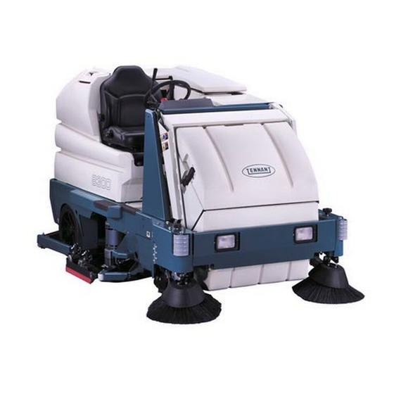
Tennant 8300 Service Manual
Hide thumbs
Also See for 8300:
- User manual ,
- Operator's manual (154 pages) ,
- Instruction bulletin (10 pages)
Table of Contents
Advertisement
Quick Links
Advertisement
Chapters
Table of Contents
Troubleshooting

Related Manuals for Tennant 8300


Summary of Contents for Tennant 8300
- Page 1 8300 Service Manual 330635 Rev. 02 (5- -02) *330635*...
- Page 2 Electrical: Battery maintenance and replacement, electrical schematics, and electrical troubleshooting. Hydraulics: Valve replacement, motor replacement, cylinder replacement, pump replacement, filter replacement, hydraulic schematic, and hydraulic troubleshooting. Manual Number -- 330635 Revision: 02 Published: 5--02 Copyright E 2000, 2001, 2002 TENNANT, Printed in U.S.A.
-
Page 3: Table Of Contents
HYDRAULIC TAPERED SEAT FITTING (JIC) TORQUE CHART ..1-20 HYDRAULIC O--RING FITTING TORQUE CHART ....1-20 8300 330635 (5- -02) - Page 4 GENERAL INFORMATION 8300 330635 (8- -00)
-
Page 5: Safety Precautions
WARNING: Raised hopper may fall. working on machine. Engage hopper support bar. - - Avoid contact with battery acid. - - Use Tennant supplied or equivalent FOR SAFETY: replacement parts. 1. Do not operate machine: - - Unless trained and authorized. - Page 6 380 mm (15 in) or less from the ground. - - Set parking brake after machine is loaded. - - Block machine tires. - - Tie machine down to truck or trailer. 8300 330635 (5- -02)
- Page 7 FOR SAFETY LABEL - - LOCATED BATTERY CHARGING LABEL - - LOCATED ON ON THE INSIDE OF THE OPERATOR THE LINTEL. COMPARTMENT. ENGINE FAN AND BELT LABEL - - LOCATED ON THE VACUUM FAN SHROUD. 8300 330635 (5- -02)
- Page 8 THE INSIDE OF THE SOLUTION TANK COVER. COMPARTMENT. HOPPER LIFT ARMS LABEL - - LOCATED HOPPER SUPPORT BAR LABEL - - LOCATED ON BOTH HOPPER LIFT ARMS. ON THE HOPPER SUPPORT BAR AND ON BOTH HOPPER LIFT ARMS. 353391 8300 330635 (5- -02)
-
Page 9: Specifications
4547 mm (179 in) Minimum turning radius, right 4648 mm (183 in) Minimum aisle turn 2946 mm (116 in) Maximum rated climb and descent angle with full tanks Maximum rated climb and descent angle with empty tanks 8300 330635 (5- -02) -
Page 10: Power Type
Kw (hp) Electric Motors Sweep brush 0.60 (.8) Scrub brush 0.75 (1) Heavy Duty scrub brush 1.12 (1.5) Vacuum fan 0.63 (0.85) Propelling 3.4 (4.6) Type Phase Chargers 208--240--480 208--240--480 208--240--480 208--240--480 208--240--480 208--240--480 208--240--480 208--240--480 8300 330635 (5- -02) -
Page 11: Steering
Mechanical drum brakes (2), one per rear wheel, cable actuated Parking brake Utilizes service brakes, cable actuated TIRES Location Type Size Front (1) Solid 413 X 152 mm (16.25 x 6 in) Rear (2) Solid 406 X 127 mm (16 x 5 in) 8300 330635 (5- -02) -
Page 12: Machine Dimensions
2641 mm (104 in) MaxProt1000 1300 mm (51 in) 1231 mm (48.5 in) MaxProt1200 1510 mm (59.5 in) TOP VIEW 2070 mm (81.5 in) 1450 mm (57 in) SIDE VIEW FRONT VIEW 353382 MACHINE DIMENSIONS 1-10 8300 330635 (5- -02) -
Page 13: Pushing, Towing, And Transporting The Machine
FOR SAFETY: When loading machine onto truck or trailer, use winch. Do not drive the machine onto the truck or trailer unless the loading surface is horizontal AND is 380 mm (15 in) or less from the ground. 1-11 8300 330635 (5- -02) - Page 14 FOR SAFETY: When unloading machine off truck or trailer, use winch. Do not drive the machine off the truck or trailer unless the loading surface is horizontal AND 380 mm (15 in) or less from the ground. 1-12 8300 330635 (5- -02)
-
Page 15: Machine Jacking
FOR SAFETY: When servicing machine, block machine tires before jacking machine up. FOR SAFETY: When servicing machine, jack machine up at designated locations only. Block machine up with jack stands. 1-13 8300 330635 (5- -02) -
Page 16: Storage Information
ESt solution pump. 2. Raise the rear squeegee and the scrub head. 3. Park the machine in a cool, dry area. 4. Remove the batteries, or charge them after every three months. 1-14 8300 330635 (5- -02) -
Page 17: Machine Troubleshooting
Solution tank empty Fill solution tank floor Solution flow lever off Open solution flow lever Solution supply lines plugged Flush solution supply lines ESt switch off Turn ESt switch on Manual control valve closed Open valve more 1-15 8300 330635 (8- -00) - Page 18 Sweeping brushes not properly Adjust brushes adjusted Debris caught in brush drive Remove debris mechanism Brush drive failure Contact Tennant service representative Hopper full Empty hopper Hopper lip skirts worn or Replace lip skirts damaged 1-16 8300 330635 (8- -00)
-
Page 19: Maintenance
Scrub head floor skirts Check for damage and wear (Disk brush heads only) Sweeping assembly side Check for damage and wear and recirculation skirts Front flap skirt Check for damage and wear Battery cells Check electrolyte level 1-17 8300 330635 (5- -02) - Page 20 Check motor brushes motors Propelling motor Check motor brushes SPL -- Special lubricant, Lubriplate EMB grease (Tennant part no. 01433--1) GL -- SAE 90 weight gear lubricant HYDO -- TENNANT or approved hydraulic fluid DW -- Distilled water NOTE: Also check procedures indicated (H) after the first 50-hours of operation.
-
Page 21: Hardware Information
They include the following: 0.75 in 215--280 313--407 (291--380) (424--552) Locktite 515 sealant -- gasket forming material. TENNANT Part No. 75567,15 oz 1.00 in 500--650 757--984 (440 ml) cartridge. (678--881) (1026--1334) NOTE: Decrease torque by 20% when using a Locktite 242 blue -- medium strength thread thread lubricant. -
Page 22: Hydraulic Fitting Information
(81 Nm) (122 Nm) 0.62 0.88--14 40 ft lb (54 Nm) NOTE: Do not use sealant on o- -ring threads. 0.75 1.12--12 70 ft lb (95 Nm) 1.31--12 90 ft lb (122 Nm) *Aluminum bodied components 1-20 8300 330635 (8- -00) - Page 23 ....2--27 HURTH GEAR BOX EXPLODED VIEW (UPPER SECTION) ....2--28 HURTH GEAR BOX REPAIR INFO ..2--29 8300 330635 (8- -00)
- Page 24 CHASSIS 8300 330635 (8- -00)
-
Page 25: Introduction
CHASSIS INTRODUCTION This section includes information on the main chassis related components for example the steering, brakes, and tires. 8300 330635 (8- -00) -
Page 26: Brakes And Tires
Surface, Set Parking Brake, Turn Off Machine And Remove Key. 1. Make sure the parking brake is not engaged. Open the RH sweep brush door. 2. Go under the front, right corner of machine frame. Locate the brake cable assembly. 8300 330635 (8- -00) - Page 27 5. Retighten the large jam nuts on the brake cable at the floor plate mounting tab. IF MORE ADJUSTMENT IS NEEDED: 1. Loosen the smaller jam nuts on the brake cable at the clevis assembly. 8300 330635 (8- -00)
- Page 28 Close the RH sweep brush door. 4. Go to the operators compartment and check the service brake pedal adjustment. The pedal should engage the service brakes with 1 inch of movement or less. 5. If needed, repeat adjustment procedure. 8300 330635 (8- -00)
-
Page 29: To Replace Brake Shoes
4. Jack up one rear corner of the machine. Place jack stands under machine. FOR SAFETY: Block machine tires before jacking machine up. Jack machine up at designated locations only. Block machine up with jack stands. 8300 330635 (8- -00) - Page 30 6. Remove the cotter pin, slotted nut, flat washer, and bearing cone. 7. Remove the tire and wheel assembly from the machine. 8. Remove the two springs holding the brake shoes together. Remove the old brake shoes. 8300 330635 (8- -00)
- Page 31 9. Position the new brake shoes on the brake mounting plate. 10. Reattach the two brake springs to the new brake shoes. 11. Pack the wheel bearings with Lubriplate EMB grease. 12. Slide the tire and wheel assembly on the axle. 8300 330635 (8- -00)
- Page 32 25--50 mm (1--2 in) before engaging brakes. 21. Tighten the brake cable jam nuts at the clevis. Close the RH sweep brush door. 22. Operate the machine and check the brakes for proper operation. 2-10 8300 330635 (8- -00)
-
Page 33: Rear Tires And Wheels
CHASSIS REAR TIRES AND WHEELS The 8300 rear tires are semi--pneumatic. Inspect the rear wheel bearings for seal damage, and repack and adjust every 1600 hours of operation. Use Lubriplate EMB grease (TENNANT part no. 01433--1). TO REPACK REAR WHEEL BEARINGS FOR SAFETY: Before Leaving Or Servicing Machine;... - Page 34 6. Remove the cotter pin, slotted nut, flat washer, and bearing cone. 7. Remove the tire and wheel assembly from the machine. 8. Pack the wheel bearings with Lubriplate EMB grease. 2-12 8300 330635 (8- -00)
- Page 35 25--50 mm (1--2 in) before engaging brakes. 17. Tighten the brake cable jam nuts at the clevis. Close the RH sweep brush door. 18. Operate the machine and check the rear wheels for proper operation. 2-13 8300 330635 (8- -00)
-
Page 36: Front Tire And Wheel, And Wheel Drive Support
Raise the machine so the front wheel is off the ground. Fill one grease fitting with Lubriplate EMB grease (TENNANT Part No. 01433--1) while rotating the gearbox from stop to stop. Fill the second grease fitting while rotating the gearbox back to the original position. -
Page 37: To Replace Front Drive Gear Box
Jack machine up at designated locations only. Block machine up with jack stands. 3. Open the cover and side door. 4. Open the battery cover and un--plug the battery connector from the machine. 2-15 8300 330635 (8- -00) - Page 38 8. Remove the hardware holding the smaller electrical panel to the left side of the steering support column. NOTE: Move the small panel back far enough so there is clearance to remove the large steering sprocket from the drive assembly. 2-16 8300 330635 (8- -00)
- Page 39 11. Remove the front tire and wheel assembly from the drive motor hub. 12. Remove the three M8 socket head cap screws holding the electric drive motor to the drive gear box. 2-17 8300 330635 (8- -00)
- Page 40 Replace the plug. 15. Loosen the hardware holding the hydraulic steering motor to the machine frame. 16. Push the steering motor in until there is slack in the steering chain. 2-18 8300 330635 (8- -00)
- Page 41 19. Remove the six hex screws holding the drive gear box to the machine frame. CAUTION: The drive gear box is very heavy and tippy when the mounting hardware is removed! 2-19 8300 330635 (8- -00)
- Page 42 25. Reinstall the hex screws using 242 blue loctite and tighten to 64 -- 83 Nm (50 -- 60 ft lb). 26. Fill the gear box case through the large hole on top, with .75 gallon of 90 weight gear lube. 2-20 8300 330635 (8- -00)
- Page 43 28. Reinstall the three M8 socket head cap screws holding the electric drive motor to the drive gear box. Tighten to 26 -- 34 Nm (20 -- 26 ft lb). 29. Install front tire. Tighten nuts to 122--150 Nm (90--110 ft lb). 2-21 8300 330635 (8- -00)
- Page 44 34. Reconnect the four electrical cables going to the drive motor. See the schematic in the ELECTRICAL section of this manual. 2-22 8300 330635 (8- -00)
- Page 45 36. Move the larger electrical panel into position and reinstall the three hex screws. Tighten to 18 -- 24 Nm (15 -- 20 ft lb). 37. Reinstall the control panel cover and detergent tank. 38. Reinstall the inside floor plate. 2-23 8300 330635 (8- -00)
- Page 46 39. Reinstall the plastic drive motor cover. 40. Plug in the battery connector. Close the battery cover. 41. Close the cover and side door. 42. Lower the machine to the ground and check the gear box for proper operation. 2-24 8300 330635 (8- -00)
-
Page 47: Steering Chain
TO ADJUST STEERING CHAIN TENSION FOR SAFETY: Before Leaving Or Servicing Machine; Stop On Level Surface, Set Parking Brake, Turn Off Machine And Remove Key. 1. Remove the plastic drive motor cover. 2. Remove the inside floor plate. 2-25 8300 330635 (8- -00) - Page 48 5. Reinstall the inside floor plate. 6. Reinstall the plastic drive motor cover. 7. Lower the machine to the ground and check the steering for proper operation. 2-26 8300 330635 (8- -00)
-
Page 49: Hurth Gearbox Exploded View (Lower Section)
CHASSIS HURTH GEARBOX EXPLODED VIEW (LOWER SECTION) 2-27 8300 330635 (8- -00) -
Page 50: Hurth Gearbox Exploded View (Upper Section)
CHASSIS HURTH GEARBOX EXPLODED VIEW (UPPER SECTION) 2-28 8300 330635 (8- -00) - Page 51 RECIRCULATION SKIRTS ..3-75 TO REPLACE REAR SKIRT ..3-75 HOPPER SEALS ....3-76 8300 330635 (5- -02)
- Page 52 SWEEPING 8300 330635 (8- -00)
-
Page 53: Introduction
SWEEPING INTRODUCTION The Hi--dump sweeper assembly on the 8300 gives the machine ability to pick up debris and dump it into a container. The sweeper assembly is mounted to the front of the machine. All components can be serviced with the sweeper mounted to the front of the machine. -
Page 54: Debris Hopper
SWEEPING DEBRIS HOPPER The debris hopper holds the material swept up by the main and side brush. The 8300 hopper is unique in that only the hopper lifts and dumps, the dust filter and shaker assembly are stationary. The side brushes also are stationary when the hopper is lifted and dumped. -
Page 55: To Adjust Hopper Primary Roll Out Chain
2. Open the top cover and side door. 3. Place a block of wood or jack stand under the front of the hopper. NOTE: Make sure the hopper is positioned tight up against the seal on the filter chamber. 8300 330635 (8- -00) - Page 56 7. Tighten the chain adjuster body tight. Make sure there is no slack in the roll--out chain. Tighten the jam nut. Make sure the chain tensioner assembly is 2- -3 links above the teeth on the large sprocket. 8300 330635 (8- -00)
- Page 57 Lower the hopper. Check to make sure the hopper seal is tight against the filter chamber. NOTE: Re- -adjust primary chain if necessary. 11. Close the top cover and side door. 8300 330635 (8- -00)
-
Page 58: To Replace Hopper Primary Roll Out Chain
2. Open the top cover and side door. 3. Place a block of wood or jack stand under the front of the hopper. NOTE: Make sure the hopper is positioned tight up against the seal on the filter chamber. 8300 330635 (8- -00) - Page 59 6. Continue to unscrew the adjuster body until the adjuster body is free from the adjuster housing. Remove the primary chain from the machine. 7. Remove the adjuster from the existing chain. Install on the new chain in the same orientation. 8300 330635 (8- -00)
- Page 60 Tighten the jam nut. Make sure the chain tensioner assembly is 2- -3 links above the teeth on the large sprocket. 11. Remove the block from under the front of the hopper. 3-10 8300 330635 (8- -00)
- Page 61 Lower the hopper. Check to make sure the hopper seal is tight against the filter chamber. See TO ADJUST PRIMARY HOPPER ROLL--OUT CHAIN instructions. 14. Close the top cover and side door. 3-11 8300 330635 (8- -00)
-
Page 62: To Adjust Hopper Secondary Roll Out Chain
1/3 of the way up. Turn off the machine. 2. Raise the rear cover and unplug the battery connector. 3. Remove the three screws holding the plastic cover to the left side lift arm. Remove the cover. 3-12 8300 330635 (8- -00) - Page 63 Tighten the jam nut. NOTE: Make sure the chain tensioner assembly is positioned about half way between the upper and lower sprockets. 7. Plug the battery connector into the machine. Close the rear cover. 3-13 8300 330635 (8- -00)
- Page 64 Check to make sure the hopper seal is tight against the filter chamber. Re- -adjust secondary chain if necessary. If needed- -- -see TO ADJUST PRIMARY HOPPER ROLL- -OUT CHAIN instructions. 9. Reinstall the left side lift arm cover. 3-14 8300 330635 (8- -00)
-
Page 65: To Replace Hopper Secondary Roll Out Chain
1/3 of the way up. Turn off the machine. 2. Remove the three screws holding the plastic cover to the left side lift arm. Remove the cover. 3. Turn on the machine and lower the hopper. 3-15 8300 330635 (8- -00) - Page 66 5. Locate the secondary roll--out chain adjuster. 6. Loosen the jam nut on the tension adjuster. 7. Continue to unscrew the adjuster body until the adjuster body is free from the adjuster housing. Remove the secondary chain from the machine. 3-16 8300 330635 (8- -00)
- Page 67 11. Tighten the chain adjuster body tight. Make sure there is no slack in the roll--out chain. Tighten the jam nut. Make sure the chain tensioner assembly is positioned about half way between the upper and lower sprockets. 3-17 8300 330635 (8- -00)
- Page 68 Check to make sure the hopper seal is tight against the filter chamber. Re- -adjust secondary chain if necessary. If needed- -- -see TO ADJUST PRIMARY HOPPER ROLL- -OUT CHAIN instructions. 14. Reinstall the left side lift arm cover. 3-18 8300 330635 (8- -00)
-
Page 69: Hopper Dust Filter
TO REPLACE HOPPER DUST FILTER FOR SAFETY: Before Leaving Or Servicing Machine; Stop On Level Surface, Set Parking Brake. 1. Un--snap the two hopper filter cover lock straps. 2. Remove the filter cover. 3-19 8300 330635 (8- -00) - Page 70 3. Disconnect the two wires from the filter shaker solenoid. 4. Remove the shaker assembly from the filter. 5. Remove the filter from the sweeper assembly. 6. Install the new debris filter into the filter housing. 3-20 8300 330635 (8- -00)
- Page 71 8. Route the shaker wires into the slits in the filter seal. 9. Reinstall the filter cover. Secure the filter cover with the two lock straps. 10. Operate the machine. Check the filter shaker for proper operation. 3-21 8300 330635 (8- -00)
-
Page 72: Main Brush
1. Open the right hand sweeper brush door. 2. Remove the knob bolt holding the lower brush arm to the brush tube. 3. Remove the three smaller plastic knobs holding the skirt plate assembly to the frame. 3-22 8300 330635 (8- -00) - Page 73 6. Flip the existing brush end to end or install a new lower main sweep brush. 7. Rotate the brush until it slips on and engages the drive plug on the left side of the sweeper assembly. 3-23 8300 330635 (8- -00)
- Page 74 Reinstall the knob bolt and tighten tight. 11. Close the right hand brush door. 12. Operate the machine. Check the new brush for proper pattern. See TO CHECK AND ADJUST MAIN BRUSH PATTERN instructions in this section. 3-24 8300 330635 (8- -00)
-
Page 75: To Replace Cylindrical Elevator
1. Open the right hand brush door. 2. Remove the hex screw holding the cylindrical elevator arm to the brush tube. 3. Remove the three nuts holding the upper skirt plate assembly to the frame. 3-25 8300 330635 (8- -00) - Page 76 6. Flip the cylindrical elevator end to end or install a new cylindrical elevator. 7. Rotate the cylindrical elevator until it slips on and engages the drive plug on the left side of the sweeper assembly. 3-26 8300 330635 (8- -00)
- Page 77 10. Position the cylindrical elevator idler arm onto the brush tube. Reinstall the hex screw and tighten tight. 11. Close the right hand brush door. 12. Operate the machine. Check the new cylindrical elevator for proper operation. 3-27 8300 330635 (8- -00)
-
Page 78: To Check And Adjust Main Brush Pattern
1. Open the right hand brush door. Locate the brush pattern adjustment bolt at the end of the cylindrical elevator arm. Adjust the bolt DOWN to increase the brush pattern. Adjust the bolt UP to decrease the brush pattern. 3-28 8300 330635 (8- -00) -
Page 79: To Adjust Main Brush Levelness
3. Loosen the three hex screws. Move the bracket up or down to achieve an even taper on the brush pattern. Tighten the hex screws to 18 -- 24 Nm (15 -- 20 ft lb). 4. Re--check the main brush pattern. 3-29 8300 330635 (8- -00) -
Page 80: Main Brush Drive Belts
1. Turn off the machine and set the machine parking brake. FOR SAFETY: Before Leaving Or Servicing Machine; Stop On Level Surface, Set Parking Brake, Turn Off Machine And Remove Key. 2. Remove the left side brush door. 3-30 8300 330635 (8- -00) - Page 81 4. Push the main brush motor forward. 5. Remove the existing primary V--belt from the motor sheave. 6. Position the new V--belt onto the motor sheave and larger two groove sheave. 3-31 8300 330635 (8- -00)
- Page 82 50 hours of operation for wear. 8. Tighten the four motor mount screws to 18 -- 24 Nm (15 -- 20 ft lb). 9. Reinstall or close the left side brush door. 10. Reconnect the battery. 3-32 8300 330635 (8- -00)
- Page 83 SWEEPING 11. Operate the machine. Check the new main brush primary drive belt for proper operation. 3-33 8300 330635 (8- -00)
-
Page 84: To Replace Main Brush Secondary Drive Belt
Servicing Machine; Stop On Level Surface, Set Parking Brake, Turn Off Machine And Remove Key. 2. Remove the left side brush door. 3. Loosen the four hex screws holding the main brush motor to the sweeper frame. 3-34 8300 330635 (8- -00) - Page 85 4. Push the main brush motor forward. 5. Remove the primary V--belt from the motor sheave. 6. Loosen the nut holding the flat idler sheave to the arm. Push the sheave up. 7. Remove the secondary V--belt from the three sheaves. 3-35 8300 330635 (8- -00)
- Page 86 The deflection should be 3 to 7mm (0.125 to 0.25 in) when a force of 2.3 kg (5 lb) is applied at the belt midpoint. The belt should be checked after every 50 hours of operation for wear. 3-36 8300 330635 (8- -00)
- Page 87 18 -- 24 Nm (15 -- 20 ft lb). 13. Reinstall the left side brush door. 14. Reconnect the battery. 15. Operate the machine. Check the new main brush secondary drive belt for proper operation. 3-37 8300 330635 (8- -00)
-
Page 88: To Replace Main Brush Idler Plug Bearing
1. Open the right hand sweeper brush door. 2. Remove the knob bolt holding the lower brush arm to the brush tube. 3. Remove the three smaller plastic knobs holding the skirt plate assembly to the frame. 3-38 8300 330635 (8- -00) - Page 89 5. Remove the skirt assembly from the idler arm. 6. Remove the nut and washer holding the main brush idler plug to the brush arm. 7. Remove the idler pug from the brush arm. 3-39 8300 330635 (8- -00)
- Page 90 9. Remove the bearing from the idler plug. 10. Use an arbor press to install the new bearing into the idler plug. 11. Reinstall the bearing retainer plate. Tighten the hex screws to 11 -- 14 Nm (7 -- 10 ft lb). 3-40 8300 330635 (8- -00)
- Page 91 14. Reinstall the skirt plate assembly onto the frame. Reinstall the three plastic knobs and tighten. 15. Position the main brush idler arm onto the brush tube. Reinstall the knob bolt and tighten tight. 3-41 8300 330635 (8- -00)
- Page 92 SWEEPING 16. Close the right hand brush door. 17. Operate the machine. Check the main sweep brush for proper pattern. See TO CHECK AND ADJUST MAIN BRUSH PATTERN instructions in this section. 3-42 8300 330635 (8- -00)
-
Page 93: To Replace Rotary Elevator Idler Plug
1. Open the right hand sweeper brush door. 2. Remove the hex screw holding the cylindrical elevator arm to the brush tube. 3. Remove the three nuts holding the upper skirt plate assembly to the frame. 3-43 8300 330635 (8- -00) - Page 94 The idler plug may need to be pried off with screw drivers or small crow bars. Discard the idler plug. 7. Use an arbor press to install the new idler plug onto the brush arm. 3-44 8300 330635 (8- -00)
- Page 95 9. Reinstall the idler arm into the cylindrical elevator and onto the sweeper frame. 10. Position the cylindrical elevator idler arm onto the brush tube. Reinstall the hex screw and tighten tight. 11. Reinstall the three knobs and tighten. 3-45 8300 330635 (8- -00)
- Page 96 SWEEPING 12. Close the right hand brush door. 13. Operate the machine. Check the new cylindrical elevator idler plug bearing for proper operation. 3-46 8300 330635 (8- -00)
-
Page 97: To Replace Main Brush Two Groove Sheave Bearings
Machine And Remove Key. 2. Locate the main brush two groove sheave on the left side of the sweeper frame. 3. Loosen the four hex screws holding the main brush motor to the sweeper frame. 3-47 8300 330635 (8- -00) - Page 98 5. Remove the primary V--belt from the two groove sheave. 6. Loosen the nut holding the flat idler sheave to the arm. Push the sheave up. 7. Remove the secondary V--belt from the two groove sheave. 3-48 8300 330635 (8- -00)
- Page 99 9. Use a crow bar or a puller to remove the two groove sheave from the shaft. 10. Use a hammer and punch to remove the bearings from the two groove sheave. 11. Use an arbor press to install the new bearings. 3-49 8300 330635 (8- -00)
- Page 100 7mm (0.125 to 0.25 in) when a force of 2.3 kg (5 lb) is applied at the belt midpoint. The belt should be checked after every 50 hours of operation for wear. 15. Position the primary V--belt onto the two groove sheave. 3-50 8300 330635 (8- -00)
- Page 101 50 hours of operation for wear. 17. Tighten the four motor mount screws to 18 -- 24 Nm (15 -- 20 ft lb). 18. Reinstall the left side brush door. 19. Reconnect the battery. 3-51 8300 330635 (8- -00)
- Page 102 SWEEPING 20. Operate the machine. Check the two groove sheave for proper operation. 3-52 8300 330635 (8- -00)
-
Page 103: To Replace Main Brush Lift Cable
FOR SAFETY: Before Leaving Or Servicing Machine; Stop On Level Surface, Set Parking Brake, Turn Off Machine And Remove Key. 3. Raise the rear cover and unplug the battery connector. 4. Remove the left side brush door. 3-53 8300 330635 (8- -00) - Page 104 5. Un--snap the two hopper filter cover lock straps. 6. Remove the filter cover. 7. Disconnect the two wires from the filter shaker solenoid. 8. Remove the shaker assembly and the filter from the machine. 3-54 8300 330635 (8- -00)
- Page 105 11. Remove the cotter pin from the bottom of the clevis pin at the end of the actuator tube. 12. Remove the clevis pin and both cables. NOTE: Note orientation of cables on the actuator. 3-55 8300 330635 (8- -00)
- Page 106 14. Remove the cable pulley from the left side of the hopper. 15. Remove the pulley from the left side of the sweeper frame, under the area of the debris filter. 16. Pull the main brush lift cable out of the machine. 3-56 8300 330635 (8- -00)
- Page 107 18 -- 24 Nm (15 -- 20 ft lb). 20. Reconnect the ends of the main brush lift cable and the debris flap cable to the tube end of the actuator using the clevis pin and cotter pin. 3-57 8300 330635 (8- -00)
- Page 108 NOTE: Reuse the clevis pin and cotter pin. 22. Reinstall the sweeper panel. 23. Install the debris filter into the filter housing. 24. Install the shaker assembly onto the new filter. 3-58 8300 330635 (8- -00)
- Page 109 25. Route the shaker wires into the slits in the filter seal. 26. Reinstall the filter cover. Secure the filter cover with the two lock straps. 27. Reconnect the battery. 28. Disengage the prop arm and lower the hopper. 3-59 8300 330635 (8- -00)
- Page 110 SWEEPING 29. Operate the machine. Check the main brush lift cable for proper operation. 30. Reinstall the left side brush door. 3-60 8300 330635 (8- -00)
-
Page 111: To Replace Large Debris Skirt Automatic Lift Cable
FOR SAFETY: Before Leaving Or Servicing Machine; Stop On Level Surface, Set Parking Brake, Turn Off Machine And Remove Key. 3. Raise the rear cover and unplug the battery connector. 4. Open the right side brush door. 3-61 8300 330635 (8- -00) - Page 112 5. Un--snap the two hopper filter cover lock straps. 6. Remove the filter cover. 7. Disconnect the two wires from the filter shaker solenoid. 8. Remove the shaker assembly and the filter from the machine. 3-62 8300 330635 (8- -00)
- Page 113 11. Remove the cotter pin from the bottom of the clevis pin at the end of the actuator tube. 12. Remove the clevis pin and both cables. NOTE: Note orientation of cables on the actuator. 3-63 8300 330635 (8- -00)
- Page 114 14. Remove the cable pulley from the right side of the hopper. 15. Remove the pulley from the right side of the sweeper frame, under the area of the debris filter. 16. Pull the main brush lift cable out of the machine. 3-64 8300 330635 (8- -00)
- Page 115 18 -- 24 Nm (15 -- 20 ft lb). 20. Reconnect the ends of the large debris skirt lift cable and the main brush cable to the tube end of the actuator using the clevis pin and cotter pin. 3-65 8300 330635 (8- -00)
- Page 116 NOTE: Reuse the clevis pin and cotter pin. 22. Reinstall the sweeper panel. 23. Install the debris filter into the filter housing. 24. Install the shaker assembly onto the new filter. 3-66 8300 330635 (8- -00)
- Page 117 25. Route the shaker wires into the slits in the filter seal. 26. Reinstall the filter cover. Secure the filter cover with the two lock straps. 27. Reconnect the battery. 28. Disengage the prop arm and lower the hopper. 3-67 8300 330635 (8- -00)
- Page 118 SWEEPING 29. Operate the machine. Check the large debris skirt lift cable for proper operation. 30. Reinstall the right side brush door. 3-68 8300 330635 (8- -00)
-
Page 119: Side Sweeping Brush
The side brush pattern adjustment is made by turning the side brush adjustment knob. The side sweeping brush(es) should be replaced when the remaining brush bristle measures 50 mm (2 in) or less in length. 03376 3-69 8300 330635 (5- -02) -
Page 120: To Adjust Side Brush Pattern
2. Pivot the side brush assembly to the position desired. Tighten the hardware to 18 -- 24 Nm (15 -- 20 ft lb). 3-70 8300 330635 (8- -00) -
Page 121: To Replace Side Brush
1. Make sure the side brush is in the raised position. 2. Reach under the side brush and remove the hair pin from the side brush motor shaft. 3. Remove the side brush, brush plate, and shaft hub. 3-71 8300 330635 (8- -00) - Page 122 4. Position the shaft hub and brush plate onto the new side brush. 5. Position the new side brush, shaft hub, and brush plate onto the side brush motor shaft. Reinstall the hair pin. 6. Operate the side brush. Check for proper operation. 3-72 8300 330635 (8- -00)
-
Page 123: Skirts And Seals
FOR SAFETY: Before Leaving Or Servicing Machine; Stop On Level Surface, Set Parking Brake. 1. Raise the hopper and engage the prop arm. 2. Locate the debris skirt at the front, lower edge of the sweeper frame. 3-73 8300 330635 (8- -00) - Page 124 6. Reinstall the five hex screws and tighten only until the rubber starts to deform slightly. 7. Disengage the prop arm and lower the hopper. Operate the machine. Check the debris skirt for proper operation. 3-74 8300 330635 (8- -00)
-
Page 125: Recirculation Skirts
Reinstall the four hex screws and tighten only until the rubber starts to deform slightly. 5. Reinstall the main sweep brush. See TO REPLACE MAIN SWEEP BRUSH instructions in this section. Operate the machine. Check the recirculation skirts for proper operation. 3-75 8300 330635 (8- -00) -
Page 126: Hopper Seals
Raise the hopper and inspect the hopper seals daily. Replace any torn or damaged seals for optimum sweeping performance. 3-76 8300 330635 (8- -00) -
Page 127: Vacuum Fan
HOPPER VACUUM FAN SEAL The vacuum fan seal is located between the hopper cover and vacuum fan inlet. Replace the vacuum fan seal if it becomes damaged. 3-77 8300 330635 (8- -00) -
Page 128: To Remove Vacuum Fan Housing
Servicing Machine; Stop On Level Surface, Set Parking Brake. 1. Raise the hopper and engage the prop arm. 2. Raise the rear cover and unplug the battery connector. 3. Open the top cover and side door. 3-78 8300 330635 (8- -00) - Page 129 6. Loosen, then remove the belt adjustment screw on the bottom of the vacuum fan assembly mount bracket. This will give slack to the V- -belt. 7. Remove the V--belt from the vacuum fan sheave. 3-79 8300 330635 (8- -00)
- Page 130 SWEEPING 8. Remove the four hex screws holding the vacuum fan housing to the mount plate. 9. Remove the vacuum housing out the front of the machine. 3-80 8300 330635 (8- -00)
-
Page 131: To Install Vacuum Fan Assembly
Loosen the set screws on the vacuum fan sheave and move it in or out to achieve good alignment. Retighten the set screws tight. 3-81 8300 330635 (8- -00) - Page 132 0.25 in) when a force of 2.3 kg (5 lb) is applied at the belt midpoint. 6. Tighten the three motor mount screws to 18 -- 24 Nm (15 -- 20 ft lb). 7. Reconnect the battery connector to the machine connector. 3-82 8300 330635 (8- -00)
- Page 133 8. Close the rear battery cover. 9. Reinstall the access panel, debris filter, and hopper cover. 10. Close the top cover and side door. Lower the hopper. 11. Operate the vacuum fan. Check for proper operation. 3-83 8300 330635 (8- -00)
-
Page 134: To Replace Vacuum Fan Impeller Bearings
2. Remove the eight small sheet metal screws holding the outer housing to the vacuum fan assembly. Pull the housing off the backing plate. 3. Hold the impeller from turning. Remove the hex nut from the center of the vacuum fan shaft. 3-84 8300 330635 (8- -00) - Page 135 6. Remove the bearing housing from the mount bracket and backing plate. 7. Use a press to remove the impeller shaft and inner bearing from the bearing housing. Press the bearing and shaft in the direction of the fan sheave. 3-85 8300 330635 (8- -00)
- Page 136 NOTE: The impeller side of the shaft must be on the flange side of the bearing housing. 11. Press the second bearing into the housing over the impeller shaft. Press the bearing in until the snap ring contacts the housing. 3-86 8300 330635 (8- -00)
- Page 137 Make sure the key and spacer are in place on the shaft. 15. Hold the impeller from turning. Install the hex nut on the impeller shaft. Tighten to 18 -- 24Nm (15 -- 20 ft lb). 3-87 8300 330635 (8- -00)
- Page 138 17. Reinstall the vacuum fan housing assembly into the machine. See TO INSTALL VACUUM FAN HOUSING ASSEMBLY instructions in this section. 18. Reconnect the battery connector to the machine connector. 19. Operate the vacuum fan. Check for proper operation. 3-88 8300 330635 (8- -00)
-
Page 139: To Tension Vacuum Fan Belt
1. Open the cover and side door. 2. Locate the vacuum fan V--belt in front of the main electrical panel. 3. Loosen the three hex screws holding the vacuum fan electric motor to the mount bracket. 3-89 8300 330635 (8- -00) - Page 140 (5 lb) is applied at the belt midpoint. 5. Tighten the three electric motor mount screws to 18 -- 24 Nm (15 -- 20 ft lb). 6. Operate the vacuum fan. Check for proper operation. 7. Close the cover and side door. 3-90 8300 330635 (8- -00)
-
Page 141: Machine Sweeping Troubleshooting
Idler arm not level Adjust arm position Main brush idler arm may be out Adjust arm position of adjustment Main brush not seated correctly Remove and reinstall main brush on drive cups 3-91 8300 330635 (8- -00) - Page 142 SWEEPING 3-92 8300 330635 (8- -00)
- Page 143 ......4--60 TO ADJUST MANUAL SOLUTION VALVE ......4--63 8300 330635 (8- -00)
- Page 144 SCRUBBING 8300 330635 (8- -00)
-
Page 145: Introduction
The brushes scrub the floor. As the machine moves forward the rear squeegee wipes the dirty solution off the floor, which is then picked up and drawn into the recovery tank by the vacuum fans. 8300 330635 (8- -00) -
Page 146: Solution Tank
FOR SAFETY: Before Leaving Or Servicing Machine; Stop On Level Surface, Set Parking Brake. 1. Make sure the solution tank (right side of machine) has been drained. 2. Raise the battery cover. Unplug the battery connector. 8300 330635 (8- -00) - Page 147 5. Remove the six hex screws holding the operator seat mount plate to the solution tank. Remove the seat assembly. 6. Go under the solution tank. Disconnect the main drain line from the bottom of the solution tank. 8300 330635 (8- -00)
- Page 148 NOTE: Remove the solution level switch assembly from the mount hole in the tank. Use this hole to attach a lifting strap. The tank will lift fairly level using this procedure. 8300 330635 (8- -00)
-
Page 149: To Install Solution Tank
2. Loosely install the two hex screws holding the solution tank to the vertical mount channel at the right side of the battery. 3. Loosely install the two hex screws holding battery cover mount plate to the inside of the solution tank. 8300 330635 (8- -00) - Page 150 Tighten screws to 18 -- 24 Nm (15 -- 20 ft lb). 6. Reconnect the main solution line to the bottom of the tank. 7. Reconnect the ESt water line to the top of the solution tank. 8300 330635 (8- -00)
- Page 151 SCRUBBING 8. Reconnect the float switch to the main harness. 9. Plug the battery connector into the main connector. 10. Close the battery cover. 8300 330635 (8- -00)
-
Page 152: Recovery Tank
FOR SAFETY: Before Leaving Or Servicing Machine; Stop On Level Surface, Set Parking Brake. 1. Make sure the recovery tank (left side of machine) has been drained. 2. Raise the battery cover. Unplug the battery connector. 4-10 8300 330635 (8- -00) - Page 153 5. Remove the bracket holding the rear squeegee vacuum hose to the side of the recovery tank. Remove the vacuum hose from the recovery tank. 6. Disconnect the scrubbing vacuum fans and vacuum switch from the main harness. 4-11 8300 330635 (8- -00)
- Page 154 Remove the two hex screws holding the front of recovery tank to the frame bracket. 10. Remove the two hex screws holding battery cover mount plate to the inside of the recovery tank. 4-12 8300 330635 (8- -00)
- Page 155 NOTE: Remove the solution level switch assembly from the mount hole in the tank. Use this hole to attach a lifting strap. The tank will lift fairly level using this procedure. 4-13 8300 330635 (8- -00)
-
Page 156: To Install Recovery Tank
2. Loosely install the two hex screws holding the recovery tank to the vertical mount channel at the right side of the battery. 3. Loosely install the two hex screws holding battery cover mount plate to the inside of the recovery tank. 4-14 8300 330635 (8- -00) - Page 157 6. Reconnect the air valve to the main harness. 7. Reinstall the vacuum hose into the vacuum hole in the recovery tank. Reinstall the bracket holding the rear squeegee vacuum hose to the side of the recovery tank. 4-15 8300 330635 (8- -00)
- Page 158 9. Reconnect the scrubbing vacuum fans and vacuum switch to the main harness. 10. Reconnect the float switch to the main harness. 11. Reinstall the clamp holding the battery cables to the back of the recovery tank. 4-16 8300 330635 (8- -00)
- Page 159 SCRUBBING 12. Plug the battery connector into the main connector. 13. Close the battery cover. 4-17 8300 330635 (8- -00)
-
Page 160: Scrub Head
SCRUBBING SCRUB HEAD The 8300 can be equipped with five different scrub heads; MAXPROt 1000, MAXPROt 1000 HD motors, MAXPROt1200 disc scrub heads. MAXPROt 1000 and 1200 cylindrical scrub heads. TO REMOVE TWO MOTOR DISC SCRUB HEAD (MAXPROt 1000) FOR SAFETY: Before Leaving Or Servicing Machine;... - Page 161 4. Remove any plastic ties holding the wires and solution lines to the scrub head. 5. Disconnect the two scrub brush motors from the main harness. 6. Disconnect the water flow solenoid from the main harness. 4-19 8300 330635 (8- -00)
- Page 162 9. Disconnect the end of the side shift cable where it attaches to the scrub head. 10. Remove the cotter pins and castle nuts from the end of the scrub head drag links where they attach to the machine frame. 4-20 8300 330635 (8- -00)
- Page 163 13. Push or pull the scrub head out the right side (operators compartment side) of the machine. The scrub head can now be removed from the machine. 4-21 8300 330635 (8- -00)
-
Page 164: To Install Two Motor Disc Scrub Head (Maxprot 1000)
2. Push or pull the scrub head into the right side (operators compartment side) of the machine. Push the head in until it is centered in the frame. 3. Position the four scrub head drag links into the frame mount holes. 4-22 8300 330635 (8- -00) - Page 165 Reinstall the cotter pins. 5. Reconnect the two scrub brush motors to the main harness. 6. Reconnect the water flow solenoid to the main harness. 7. Reconnect the solution line to the water flow solenoid. 4-23 8300 330635 (8- -00)
- Page 166 UPPER head lift roller into the mount bracket. Reinstall the roller mount screw and tighten to 18 -- 24 Nm (15 -- 20 ft lb). 11. Reconnect the end of the side shift cable where it attaches to the scrub head. 4-24 8300 330635 (8- -00)
- Page 167 SCRUBBING 12. Reconnect the end of the side shift gas spring where it attaches to the scrub head. 13. Turn on the machine and raise the scrub head. Check the scrub head for proper operation. 4-25 8300 330635 (8- -00)
-
Page 168: To Remove Three Motor Disc
Remove the roller from the scrub head frame. 3. Turn on the machine and raise the scrub head. Turn off the key. 4. Remove any plastic ties holding the wires and solution lines to the scrub head. 4-26 8300 330635 (8- -00) - Page 169 6. Disconnect the water flow solenoid from the main harness. 7. Disconnect the solution line from the water flow solenoid. 8. Disconnect the end of the side shift gas spring where it attaches to the scrub head. 4-27 8300 330635 (8- -00)
- Page 170 11. Pull the drag links out of the frame mount holes. 12. If a hoist is available- -- -raise the front of the machine and place jackstands under the corners of the machine frame. 4-28 8300 330635 (8- -00)
- Page 171 SCRUBBING 13. Push or pull the scrub head out the right side (operators compartment side) of the machine. The scrub head can now be removed from the machine. 4-29 8300 330635 (8- -00)
-
Page 172: Scrub Head (Maxprot 1200)
2. Push or pull the scrub head into the right side (operators compartment side) of the machine. Push the head in until it is centered in the frame. 3. Position the two scrub head drag links into the frame mount holes. 4-30 8300 330635 (8- -00) - Page 173 Reinstall the cotter pins. 5. Reconnect the three scrub brush motors to the main harness. 6. Reconnect the water flow solenoid to the main harness. 7. Reconnect the solution line to the water flow solenoid. 4-31 8300 330635 (8- -00)
- Page 174 UPPER head lift roller into the mount bracket. Reinstall the roller mount screw and tighten to 18 -- 24 Nm (15 -- 20 ft lb). 11. Reconnect the end of the side shift cable where it attaches to the scrub head. 4-32 8300 330635 (8- -00)
- Page 175 SCRUBBING 12. Reconnect the end of the side shift gas spring where it attaches to the scrub head. 13. Turn on the machine and raise the scrub head. Check the scrub head for proper operation. 4-33 8300 330635 (8- -00)
-
Page 176: Scrub Head (Maxprot 1200)
3. Go under the machine in the area of the center of the scrub head. Remove the hex screw holding the UPPER head lift roller to the mount bracket. Remove the roller from the scrub head frame. 4-34 8300 330635 (8- -00) - Page 177 5. Remove any plastic ties holding the wires to the scrub head. 6. Disconnect the two scrub brush motors from the main harness. 7. Disconnect the water flow solenoid from the main harness. 8. Disconnect the solution line from the water flow solenoid. 4-35 8300 330635 (8- -00)
- Page 178 UPPER scrub head drag links where they attach to the machine frame. 13. Pull the drag links out of the frame mount holes. Disconnect the kick--in guard from the front, right corner of the scrub head. 4-36 8300 330635 (8- -00)
- Page 179 15. Push or pull the scrub head out the right side (operators compartment side) of the machine. The scrub head can now be removed from the machine. 4-37 8300 330635 (8- -00)
-
Page 180: To Install Cylindrical Scrub
2. Push or pull the scrub head into the right side (operators compartment side) of the machine. Push the head in until it is centered in the frame. 3. Position the four scrub head drag links into the frame mount holes. 4-38 8300 330635 (8- -00) - Page 181 Tighten the castle nuts tight. Reinstall the cotter pins. 6. Reconnect the two scrub brush motors to the main harness. 7. Reconnect the water flow solenoid to the main harness. 4-39 8300 330635 (8- -00)
- Page 182 UPPER head lift roller into the mount bracket. Reinstall the roller mount screw and tighten to 18 -- 24 Nm (15 -- 20 ft lb). 12. Reconnect the end of the side shift cable where it attaches to the scrub head. 4-40 8300 330635 (8- -00)
- Page 183 14. Turn on the machine and raise the scrub head. Check the scrub head for proper operation. 15. Reinstall the debris tray into the right side of the machine. 16. Operate the machine and check the scrub head for proper operation. 4-41 8300 330635 (8- -00)
-
Page 184: To Replace Cylindrical Scrub Head Drive Plug Shaft Bearings
2. Remove the cogged drive belt from the scrub brush drive sheave. See TO REPLACE CYLINDRICAL SCRUB HEAD BRUSH MOTOR instructions in the ELECTRICAL section. 3. Remove the three hex screws holding the cogged drive sheave to the shaft hub. 4-42 8300 330635 (8- -00) - Page 185 6. Remove the snap ring from the end of the outside shaft bearing. 7. Remove the screw and washer holding the scrub brush drive plug to the shaft. 4-43 8300 330635 (8- -00)
- Page 186 12. Install the new bearings and shaft assembly into the bearing housing (tap the assembly into the housing from the center of the scrub head to the outside of the scrub head). The longer shaft end goes to the outside of flange. 4-44 8300 330635 (8- -00)
- Page 187 Hand tighten the set screw tight. 16. Position the cogged sheave onto the shaft hub. Reinstall the three hex screws. Tighten to 8 -- 10 Nm (5 -- 7 ft lb). 4-45 8300 330635 (8- -00)
- Page 188 BRUSH MOTOR instructions in the ELECTRICAL section. 18. Reinstall the scrub brush onto the drive plug. See TO REPLACE CYLINDRICAL SCRUB BRUSH instructions in this section. 19. Operate the machine and check the scrub head for proper operation. 4-46 8300 330635 (8- -00)
-
Page 189: To Replace Cylindrical Scrub Head Idler Plug Shaft Bearing
REPLACE CYLINDRICAL SCRUB BRUSH instructions in this section. 2. Remove the scrub brush idler plate from the scrub head. 3. Remove the hex screw holding the brush idler plug and cam assembly to the mount plate. 4-47 8300 330635 (8- -00) - Page 190 5. Remove the four screws holding the bearing retainer plate to the idler hub. 6. Remove the retainer plate to expose the idler bearing. 7. Use a mechanical arbor press to remove the existing bearing and to install the new bearing. 4-48 8300 330635 (8- -00)
- Page 191 See TO REPLACE CYLINDRICAL SCRUB BRUSH instructions in this section. 12. Operate the machine and check the cylindrical scrub brush patterns. See CHECKING AND ADJUSTING CYLINDRICAL BRUSH PATTERN instructions in this section. 4-49 8300 330635 (8- -00)
-
Page 192: Disc Scrub Head Skirts
SCRUBBING DISC SCRUB HEAD SKIRTS The 8300 disc scrub heads are equipped with rubber skirts front and rear. These skirts control water spray during the scrubbing operation. TO REPLACE DISC SCRUB HEAD SKIRTS FOR SAFETY: Before Leaving Or Servicing Machine; Stop On Level Surface, Set Parking Brake. -
Page 193: Scrub Brushes
0.38 in (10 mm) or less in length. NOTE: Be sure to replace the scrub brushes in sets. Otherwise one scrub brush will be more aggressive than the other. 4-51 8300 330635 (8- -00) -
Page 194: To Replace Disc Scrub Brush
Turn the machine off. 2. Lift the side squeegee up and engage the double scrub clips. 3. Reach into the scrub brush area and spin the scrub brush until the spring clips are visible. 4-52 8300 330635 (8- -00) - Page 195 6. Position the new scrub brush under the scrub head. Line up the motor drive plug with the brush drive insert. 7. Push the scrub brush up until the spring clips lock onto the drive hub. 4-53 8300 330635 (8- -00)
-
Page 196: Cylindrical Scrub Brushes
FOR SAFETY: Before Leaving Or Servicing Machine; Stop On Level Surface, Set Parking Brake. 3. Open the side squeegee support guard with the latch. Swing the support guard outward to access the idler support casting. 4-54 8300 330635 (8- -00) - Page 197 Guide the new brush onto the drive hub. 7. Insert the Idler plug (on the inside of the idler door), into the brush. 8. Secure the idler support casting with the idler support latch. 4-55 8300 330635 (8- -00)
- Page 198 SCRUBBING 9. Firmly close the side squeegee support guard. 10. Repeat for the other brush on the other side of the scrub head. 4-56 8300 330635 (8- -00)
-
Page 199: Cylindrical Brush Pattern
5. Observe the shape of the brush patterns. If the brush patterns have parallel sides, the brushes do not need adjustment. If one, or both of the brush patterns are tapered, the brushes need adjustment to straighten the brush pattern. 4-57 8300 330635 (8- -00) - Page 200 4. Check the brush patterns again and readjust as necessary until both patterns are the same. 6. If one brush pattern is wider than the other, the scrub head needs to be leveled. 4-58 8300 330635 (8- -00)
- Page 201 SCRUBBING Level the scrub head by turning the scrub head links. Both scrub head links should be adjusted equally. Check the brush patterns again and readjust as necessary until both patterns are the same. 4-59 8300 330635 (8- -00)
-
Page 202: Manual Solution Valve
SCRUBBING MANUAL SOLUTION VALVE The 8300 manual solution valve is located under the front of the solution/recovery tanks. The manual valve is controlled with the solution lever on the left side of the steering column. The manual valve controls the amount of water going to the electric solution solenoid (located on the scrub head). - Page 203 5. Remove the two screws holding the valve to the mount bracket. Remove the valve from the machine. 6. Remove the two fittings and install into the new valve. 4-61 8300 330635 (8- -00)
- Page 204 10. Reconnect the push/pull cable to the valve lever. Reinstall the clevis pin and cotter pin. 11. Fill the solution tank and check the new valve for proper operation. See TO ADJUST MANUAL WATER VALVE instructions. 4-62 8300 330635 (8- -00)
-
Page 205: To Adjust Manual Solution Valve
2. Locate the manual solution valve push/pull cable on the left side of the steering column. 3. Loosen the large jam nuts holding the cable to the mount bracket. Move the cable in or out. Retighten the jam nuts. 4-63 8300 330635 (8- -00) -
Page 206: Squeegees
SCRUBBING SQUEEGEES The 8300 is equipped with two side squeegees and one rear squeegee. The rear squeegee comes in two different widths (Maxprot 1000 and 1200). The squeegee assemblies have replaceable rubber blades. SIDE SQUEEGEES The side squeegees control water spray and channel water into the path of the rear squeegee. - Page 207 The new blade will slip on with less resistance. 5. Reinstall the metal retainer and plastic tip. 6. Reinstall the clevis pin and hair pin. 7. Operate the machine and check the side squeegee for proper operation. 4-65 8300 330635 (8- -00)
-
Page 208: To Adjust Side Squeegees
Flip the double scrub clip over so it engages the notch in the squeegee arm. The squeegee will stay in the up position until the clips are moved back. NOTE: The clips can also be used when changing the scrub brushes. 4-66 8300 330635 (8- -00) -
Page 209: Rear Squeegee
1. Make sure the rear squeegee is in the raised position. Pull the vacuum hose out of the squeegee frame. 2. Loosen the hardware holding the squeegee frame to the lift assembly. Pull the squeegee frame and blade assembly off the machine. 4-67 8300 330635 (8- -00) - Page 210 NOTE: Make sure the slots in the blade match up with the tangs on the frame. 6. Reinstall the squeegee band. NOTE: Make sure the slots in the band match up with the tangs on the frame. 4-68 8300 330635 (8- -00)
- Page 211 SCRUBBING 7. Flip the squeegee band lock into place and snap down to lock. 8. Repeat this procedure for the front and rear blades. 4-69 8300 330635 (8- -00)
-
Page 212: To Adjust Rear Squeegee Deflection
6. Recheck the deflection of the squeegee. If squeegee deflection is even across the entire length of the blades----tighten the jam nut. If needed----repeat the previous step. 7. Operate the machine and check the rear squeegee for proper operation. 4-70 8300 330635 (8- -00) -
Page 213: To Level Rear Squeegee
5. Recheck the levelness of the squeegee. If the squeegee blade is even across the entire length----tighten the jam nut. If needed----repeat the previous step. 6. Operate the machine and check the rear squeegee for proper operation. 4-71 8300 330635 (8- -00) -
Page 214: To Replace Rear Squeegee Lift Cable
4. Remove the cotter pin from the long clevis pin in front of the squeegee lift cable roller. Remove the clevis pin and the lift cable from the machine. 4-72 8300 330635 (8- -00) - Page 215 8. Reattach the squeegee lift cable to the actuator squeegee lift bracket using the clevis pin and cotter pin. 9. Operate the machine. Check the rear squeegee for proper operation. 4-73 8300 330635 (8- -00)
-
Page 216: To Remove Rear Squeegee Assembly
2. Loosen the hardware holding the squeegee frame to the lift assembly. Pull the squeegee frame and blade assembly off the machine. 3. Remove the four hex screws holding the rear squeegee assembly to the machine frame. 4-74 8300 330635 (8- -00) - Page 217 SCRUBBING 4. Pull the squeegee assembly away from the rear of the machine. 5. Disconnect the squeegee lift actuator from the main harness. The squeegee assembly can now be removed from the machine. 4-75 8300 330635 (8- -00)
-
Page 218: To Install Rear Squeegee Assembly
37 -- 48 Nm (26 -- 34 ft lb). 4. Reinstall the squeegee blade assembly frame onto the lift bracket. Position the vacuum hose into the hole in the squeegee frame. 5. Operate the machine and check the squeegee assembly for proper operation. 4-76 8300 330635 (8- -00) -
Page 219: Vacuum Fans
Servicing Machine; Stop On Level Surface, Set Parking Brake. 1. Raise the battery cover. Unplug the battery connector. 2. Open the top cover and side door. 3. Disconnect the vacuum fans from the main harness. 4-77 8300 330635 (8- -00) - Page 220 5. Remove the six M8 hex screws holding the scrub vacuum fan assembly to the front of recovery tank. 6. Remove the vacuum fan assembly from the machine. 7. Check the tank gasket for rips or tears. Replace if needed. 4-78 8300 330635 (8- -00)
-
Page 221: To Install Vacuum Fan Assembly
NOTE: If machine is equipped with the ES/AUTO FILL option- -- -adjust the mount bracket to the middle of the slots. 2. Reconnect the vacuum fan motors to the main harness. 3. Reconnect the vacuum switch to the main harness. 4-79 8300 330635 (8- -00) - Page 222 SCRUBBING 4. Plug the battery into the connector. 5. Close the top cover and side door. 6. Operate the machine. Check the scrubbing vacuum fans for proper operation. 4-80 8300 330635 (8- -00)
-
Page 223: To Replace Individual Vacuum Fan
Servicing Machine; Stop On Level Surface, Set Parking Brake. 1. Raise the battery cover. Unplug the battery connector. 2. Open the top cover and side door. 3. Disconnect the vacuum fans from the main harness. 4-81 8300 330635 (8- -00) - Page 224 Note orientation of exhaust port. 6. Check the gasket on the back of the vacuum fan for rips or tears before installing on the mount bracket. 7. Position the new vacuum fan onto the fan mount bracket. 4-82 8300 330635 (8- -00)
- Page 225 9. Reconnect the vacuum fan to the main electrical harness. 10. Plug the battery into the connector. 11. Close the top cover and side door. 12. Operate the machine. Check the scrubbing vacuum fans for proper operation. 4-83 8300 330635 (8- -00)
- Page 226 ESt system does not fill solution Clogged solution pump or lines. Flush ESt system. tank. ESt float switch(es) stuck. Clean switch floats of debris. Clogged ESt filter. Clean filter. Water levels too low in tanks. Add water. 4-84 8300 330635 (8- -00)
- Page 227 ..5-108 DISABLED ....5-136 WIRE HARNESSES GROUP ..5-112 DETERGENT PUMP ENABLED5-136 8300 330635 (5- -02)
- Page 228 ....5-188 SWEEPER VACUUM ACTIVATION5-191 SWEEP SIDE BRUSH SYSTEM TESTING ....5-194 8300 330635 (5- -02)
-
Page 229: Introduction
ELECTRICAL INTRODUCTION The 8300 electrical system consists of the batteries, instrument panel, control panels, traction motor, actuators, pumps, switches, relays, circuit board, and circuit breakers. 8300 330635 (8- -00) -
Page 230: Batteries
If one or more of the battery cells test lower than the other battery cells (0.050 or more), the cell is damaged, shorted, or is about to fail. 04380 8300 330635 (8- -00) -
Page 231: To Charge Batteries
The support arm will engage when the cover is lifted all the way up. WARNING: Batteries emit hydrogen gas. Explosion or fire can result. Keep sparks and open flame away. Keep covers open when charging. 4. Open the rear battery compartment door. 8300 330635 (8- -00) - Page 232 9. Plug the battery charger into the wall outlet. NOTE: If the red “ABNORMAL CYCLE” lamp lights when the TENNANT charger is plugged into a wall outlet, the charger can not charge the battery and there is something wrong with the battery.
- Page 233 FOR SAFETY: When maintaining or servicing machine, avoid contact with battery acid. 08247 15. Close the rear battery compartment door. Disengage the support arm, and close the top battery compartment cover. 8300 330635 (8- -00)
-
Page 234: Circuit Breakers
15 A Lights 15 A Horn CB10 20 A Scrub Vac Fan #1 CB11 20 A Scrub Vac Fan #2 CB12 25 A Control Board CB13 40 A Center Scrub Motor CB14 40 A Power Steering Pump 8300 330635 (5- -02) -
Page 235: To Replace Circuit Breaker
FOR SAFETY: Before Leaving Or Servicing Machine; Stop On Level Surface, Set Parking Brake. 1. Raise the rear cover and unplug the battery connector. 2. Open the top cover and side door. 3. Remove the plastic traction motor cover. 8300 330635 (8- -00) - Page 236 7. Install the new circuit breaker (with the same amp rating) into the mount hole. Reinstall the rubber boot and hand tighten. 8. Reconnect the wires to the back of the new circuit breaker. 5-10 8300 330635 (8- -00)
- Page 237 9. Reinstall the plastic traction motor cover. 10. Close the top cover and side door. 11. Plug the battery connector into the machine. Close the rear cover. 12. Operate the machine. Check the new circuit breaker for proper operation. 5-11 8300 330635 (8- -00)
-
Page 238: Fuse
TO REPLACE PROPELLING FUSE FOR SAFETY: Before Leaving Or Servicing Machine; Stop On Level Surface, Set Parking Brake. 1. Raise the rear cover and unplug the battery connector. 2. Open the top cover and side door. 5-12 8300 330635 (8- -00) - Page 239 6. Pull one end of the fuse up, then remove the fuse from the standoff. 7. Install the new propelling fuse in the same orientation. Hand tighten the two hex screws tight. 5-13 8300 330635 (8- -00)
- Page 240 9. Close the top cover and side door. 10. Plug the battery connector into the machine. Close the rear cover. 11. Operate the machine. Check the propelling circuit for proper operation. 5-14 8300 330635 (8- -00)
-
Page 241: Instrument Panel
TO REPLACE TOUCH PANEL FOR SAFETY: Before Leaving Or Servicing Machine; Stop On Level Surface, Set Parking Brake. 1. Raise the rear cover and unplug the battery connector. 2. Open the top cover and side door. 5-15 8300 330635 (8- -00) - Page 242 4. Remove the four wing nuts from the studs of the touch panel bezel. 5. Pull the bezel off the touch panel. 6. Remove the four screws holding the cover on the small control panel. 5-16 8300 330635 (8- -00)
- Page 243 Remove the touch panel and ribbon cable from the machine. 10. Install the new touch panel and ribbon assembly on the dash mount plate. Route the ribbon cable through the grommet and dash slot. 5-17 8300 330635 (8- -00)
- Page 244 12. Plug the ribbon cable into the circuit board. 13. Reinstall the small control panel cover. Tighten the screws to 11 -- 14 Nm (7 -- 10 ft lb). 14. Position the touch panel and bezel onto the dash plate. 5-18 8300 330635 (8- -00)
- Page 245 11 -- 14 Nm (7 -- 10 ft lb). 17. Close the top cover and side door. 18. Plug the battery connector into the machine. Close the rear cover. 19. Operate the machine. Check the touch panel for proper operation. 5-19 8300 330635 (8- -00)
-
Page 246: To Replace Scrubbing Circuit Board
Surface, Set Parking Brake. 1. Raise the rear cover and unplug the battery connector. 2. Open the top cover and side door. 3. Remove the four screws holding the cover on the small control panel. 5-20 8300 330635 (8- -00) - Page 247 Remove the board from the machine. Note orientation of the board. 8. Position the new circuit board onto the panel cover in the same orientation as the old one was removed. 5-21 8300 330635 (8- -00)
- Page 248 11. Reconnect the wire connectors on top of the circuit board. 12. Position the panel cover back on the control box. Reinstall the hardware and tighten to 11 -- 14 Nm (7 -- 10 ft lb). 5-22 8300 330635 (8- -00)
- Page 249 ELECTRICAL 13. Close the top cover and side door. 14. Plug the battery connector into the machine. Close the rear cover. 15. Operate the machine. Check the circuit board for proper operation. 5-23 8300 330635 (8- -00)
-
Page 250: To Replace Sweeping Circuit Board
Surface, Set Parking Brake. 1. Raise the rear cover and unplug the battery connector. 2. Open the top cover and side door. 3. Remove the four screws holding the cover on the small control panel. 5-24 8300 330635 (8- -00) - Page 251 Remove the board from the machine. Note orientation of the board. 8. Position the new circuit board onto the panel cover in the same orientation as the old one was removed. 5-25 8300 330635 (8- -00)
- Page 252 11. Reconnect the wire connectors on top of the circuit board. 12. Position the panel cover back on the control box. Reinstall the hardware and tighten to 11 -- 14 Nm (7 -- 10 ft lb). 5-26 8300 330635 (8- -00)
- Page 253 ELECTRICAL 13. Close the top cover and side door. 14. Plug the battery connector into the machine. Close the rear cover. 15. Operate the machine. Check the circuit board for proper operation. 5-27 8300 330635 (8- -00)
-
Page 254: Directional Pedal
Reverse: Press the bottom of the directional pedal with the heel of your foot. Neutral: Take your foot off the directional pedal and it will return to the neutral position. 5-28 8300 330635 (8- -00) -
Page 255: To Replace Curtis Directional Control Unit
Surface, Set Parking Brake, Turn Off Machine And Remove Key. 1. Raise the rear cover and unplug the battery connector. 2. Open the top cover and side door. 3. Unplug the directional control unit from the main harness. 5-29 8300 330635 (8- -00) - Page 256 Curtis unit when it is in the neutral position. 7. Loosen the hex screw and nut holding the lever and rod to the Curtis accelerator unit. Remove the lever and rod assembly from the unit. 5-30 8300 330635 (8- -00)
- Page 257 Reinstall the M6 nyloc nut and tighten to 7.6 -- 9.9 Nm (5 -- 6 ft lb). approx. 4 inch 5-31 8300 330635 (8- -00)
- Page 258 13. Close the top cover and side door. 14. Plug the battery connector into the machine. Close the rear cover. 15. Start the machine. Move the accelerator into the forward and reverse positions checking for proper operation. 5-32 8300 330635 (8- -00)
-
Page 259: To Replace Traction Motor Controller
Machine And Remove Key. 1. Raise the rear cover and unplug the battery connector. 2. Open the top cover and side door. 3. Remove the detergent tank and main control panel cover from the machine. 5-33 8300 330635 (8- -00) - Page 260 6. Remove the four hex screws holding the controller to the control panel. Remove the controller from the machine. 7. Cover the back side of the new controller with electrical thermal grease. 5-34 8300 330635 (8- -00)
- Page 261 9. Reconnect the electrical cables and smaller wires leading to the top of the controller. 10. Reinstall the detergent tank and main control panel cover onto the machine. 11. Close the top cover and side door. 5-35 8300 330635 (8- -00)
- Page 262 ELECTRICAL 12. Plug the battery connector into the machine. Close the rear cover. 13. Start the machine. Check the new traction motor controller for proper operation. 5-36 8300 330635 (8- -00)
-
Page 263: To Replace 36V Relay
Machine And Remove Key. 1. Raise the rear cover and unplug the battery connector. 2. Open the top cover and side door. 3. Remove the detergent tank and main control panel cover from the machine. 5-37 8300 330635 (8- -00) - Page 264 6. Remove the two hex screws holding the 36V relay to the control panel. Remove the relay from the machine. 7. Install the new 36V relay onto the control panel. Reinstall the two hex screws. Hand tighten lightly----do not over tighten. 5-38 8300 330635 (8- -00)
- Page 265 10. Close the top cover and side door. 11. Plug the battery connector into the machine. Close the rear cover. 12. Start the machine. Check the new traction motor controller for proper operation. 5-39 8300 330635 (8- -00)
-
Page 266: To Replace Traction Motor
FOR SAFETY: Block machine tires before jacking machine up. Jack machine up at designated locations only. Block machine up with jack stands. 3. Open the top cover and side door. 5-40 8300 330635 (8- -00) - Page 267 5. Remove the plastic traction motor cover. 6. Mark and disconnect the four electrical cables leading to the traction motor. 7. Remove the front tire and wheel assembly from the traction motor hub. 5-41 8300 330635 (8- -00)
- Page 268 Go far enough up the side of the motor so the mark can be seen when the motor is in its position in the drive gear box. 5-42 8300 330635 (8- -00)
- Page 269 Tighten to 26 -- 34 Nm (20 -- 26 ft lb). 14. Install front tire. Tighten nuts to 122--150 Nm (90--110 ft lb). 15. Reconnect the four electrical cables going to the traction motor. See the schematic in this section. 5-43 8300 330635 (8- -00)
- Page 270 16. Reinstall the plastic traction motor cover. 17. Plug in the battery connector. Close the battery cover. 18. Close the top cover and side door. 19. Lower the machine to the ground and check the new traction motor for proper operation. 5-44 8300 330635 (8- -00)
-
Page 271: Propel Motor Breakdown
ELECTRICAL PROPEL MOTOR BREAKDOWN 5-45 8300 330635 (8- -00) -
Page 272: To Replace Disc Scrub Head Brush Motor
REPLACE DISC SCRUB BRUSH instructions in SCRUBBING section. 2. Disconnect the motor from the main harness. 3. Go under the scrub head and remove the hex screw holding the scrub brush drive plug to the brush motor. 5-46 8300 330635 (8- -00) - Page 273 6. Start the machine and lower the scrub head. Shut off the machine. 7. Remove the motor from the machine. Note the orientation of the motor on the top of the scrub head. 5-47 8300 330635 (8- -00)
- Page 274 10. Start the machine and raise the scrub head. Shut off the machine. 11. Reinstall the four hex screws holding the motor to the scrub head. Tighten to 18 -- 24 Nm (15 -- 20 ft lb). 5-48 8300 330635 (8- -00)
- Page 275 Tighten to 18 -- 24 Nm (15 -- 20 ft lb). 14. Reinstall the scrub brushes. See TO REPLACE DISC SCRUB BRUSH instructions in SCRUBBING section. 15. Operate the machine. Check the new scrub brush motor for proper operation. 5-49 8300 330635 (8- -00)
-
Page 276: To Replace Cylindrical Scrub Head Brush Motor
2. Disconnect the motor from the main harness. 3. Remove the screws holding the plastic belt cover to the side of the scrub head. Remove the cover. 5-50 8300 330635 (8- -00) - Page 277 5. Loosen the hex screws holding the brush motor support strap to the mount bracket. 6. Let the scrub brush motor drop down in the slots. 7. Remove the cogged drive belt from the grooved pulley on the brush motor. 5-51 8300 330635 (8- -00)
- Page 278 Hand tighten the allen screws tight. 11. Position the new motor onto the scrub head. Reinstall the four hex screws. Leave loose for now. 12. Position the cogged brush drive belt over the motor pulley. 5-52 8300 330635 (8- -00)
- Page 279 Move the upper pulley in or out if needed. 16. Reinstall the plastic belt cover. Reinstall the five pan screws holding the plastic cover to the scrub head. Hand tighten the screws tight. 5-53 8300 330635 (8- -00)
- Page 280 17. Connect the new motor to the main electrical harness. 18. Reinstall the scrub brushes. See TO REPLACE CYLINDRICAL SCRUB BRUSH instructions in SCRUBBING section. 19. Operate the machine. Check the scrub brush motor for proper operation. 5-54 8300 330635 (8- -00)
-
Page 281: To Replace Scrub Head Lift Actuator
3. Go to the operators compartment and remove the cotter pin and clevis pin from the actuator where it attaches to the scrub head lift pivot bracket. 5-55 8300 330635 (8- -00) - Page 282 7. Position the new lift actuator in the machine. The actuator motor should be pointing to the left side of the machine. 8. Reinstall the clevis pin and cotter pin into the actuator where it attaches to the machine frame (battery compartment). 5-56 8300 330635 (8- -00)
- Page 283 (operators compartment). 10. Reconnect the scrub head lift actuator to the main harness. 11. Operate the machine. Check the scrub head lift actuator for proper operation. 5-57 8300 330635 (8- -00)
-
Page 284: To Replace "Failed" Scrub Head Lift Actuator
1. Jack up the front of the machine until the scrub and brushes are off the floor and the pressure on the bottom die spring has been eliminated. 2. Go to step 3 in the TO REPLACE SCRUB HEAD LIFT ACTUATOR instructions. 5-58 8300 330635 (8- -00) -
Page 285: To Replace Rear Squeegee Lift Actuator
2. Loosen the hardware holding the squeegee frame to the lift assembly. Pull the squeegee frame and blade assembly off the machine. 3. Remove the four hex screws holding the rear squeegee assembly to the machine frame. 5-59 8300 330635 (8- -00) - Page 286 7. Remove the cotter pin and clevis pin from the rod end of the actuator where it attaches to the squeegee lift cable pivot bracket. Remove the actuator from the machine. 5-60 8300 330635 (8- -00)
- Page 287 Reconnect the squeegee lift actuator to the main harness. 11. Position the squeegee assembly onto the back of the machine frame. MAXPROt 1000: Use the left hand bolt pattern. MAXPROt 1200: Use the right hand bolt pattern. 5-61 8300 330635 (8- -00)
- Page 288 37 -- 48 Nm (26 -- 34 ft lb). 13. Reinstall the squeegee blade assembly frame onto the lift bracket. Position the vacuum hose into the hole in the squeegee frame. 14. Operate the machine and check the squeegee assembly for proper operation. 5-62 8300 330635 (8- -00)
-
Page 289: To Replace Side Shift Actuator
1. Make sure the scrub head is retracted in under the machine. 2. Go under the machine on the left side, under the recovery tank. 3. Locate the scrub head side shift actuator above the front of the scrub head. 5-63 8300 330635 (8- -00) - Page 290 6. Remove the cotter pin and clevis pin from the end of the actuator where it attaches to the machine frame. Remove the actuator from the machine. 7. Position the new actuator in the machine. Reinstall the two clevis pins and cotter pins. 5-64 8300 330635 (8- -00)
- Page 291 ELECTRICAL 8. Reconnect the side shift actuator to the main harness. 9. Operate the machine and check the side shift actuator for proper operation. 5-65 8300 330635 (8- -00)
-
Page 292: Est Pump
Shut off the machine. 2. Go under the machine on the right side and locate the ESt pump on the mount bracket between the back wheels. 3. Disconnect the ESt pump from the main harness. 5-66 8300 330635 (8- -00) - Page 293 ESt pump to the mount bracket. Remove the ESt pump from the machine. 7. Remove the fittings from the existing ESt pump. Install fittings in the new pump in the same orientation as they were removed. 5-67 8300 330635 (8- -00)
- Page 294 10. Reinstall the recovery tank hose onto the lower fitting on the ESt pump. Tighten the wormdrive clamp. 11. Reconnect the ESt pump to the main harness. 12. Operate the machine and check the new ESt pump for proper operation. 5-68 8300 330635 (8- -00)
-
Page 295: Detergent Pump
1. Start the machine and lower the scrub head. Shut off the machine. 2. Go under the machine on the left side, under the recovery tank. 3. Locate the detergent pump on the left hand frame leg. 5-69 8300 330635 (8- -00) - Page 296 6. Remove the two hex screws holding the detergent pump to the mount bracket. Remove the pump from the machine. 7. Position the new detergent pump on the mount bracket. Reinstall the two screws and tighten. 5-70 8300 330635 (8- -00)
- Page 297 NOTE: Make sure the hose leading from the detergent tank is attached to the top fitting. 9. Reconnect the detergent pump to the main harness. 10. Operate the machine and check the new detergent pump for proper operation. 5-71 8300 330635 (8- -00)
-
Page 298: To Replace Auto Fill Valves
1. Drain the solution and recovery tanks. 2. Start the machine and lower the scrub head. Shut off the machine. 3. Go under the machine on the left side, under the recovery tank, ahead of the left, rear wheel. 5-72 8300 330635 (8- -00) - Page 299 6. Mark and disconnect the three hoses leading to the autofill valve assembly. 7. Remove the three screws holding the autofill valve assembly retainer bracket to the pump mount bracket. Remove the assembly from the machine. 5-73 8300 330635 (8- -00)
- Page 300 8. Remove the fitting from the autofill valve. 9. Remove the autofill valve from the plastic tee fitting. 10. If replacing left hand autofill valve----note orientation of valve and fittings. 11. If replacing right hand autofill valve----note orientation of valve and fittings. 5-74 8300 330635 (8- -00)
- Page 301 11 -- 14 Nm (7 -- 10 ft lb). 13. Reconnect the three hoses to the autofill valve assembly. 14. Reconnect the valve solenoids to the main harness. 15. Operate the machine and check the new autofill valve for proper operation. 5-75 8300 330635 (8- -00)
-
Page 302: To Replace Solution Solenoid Valve
1. Drain the solution and recovery tanks. 2. Start the machine and lower the scrub head. Shut off the machine. 3. Go under the machine on the left side, under the recovery tank, ahead of the left, rear wheel. 5-76 8300 330635 (8- -00) - Page 303 6. Loosen the worm drive clamps and remove the water lines leading to the solenoid valve. 7. Remove the two screws holding the solenoid valve to the mount bracket. Remove the solenoid valve from the machine. 5-77 8300 330635 (8- -00)
- Page 304 9. Connect the new valve to the main harness. 10. Position the two water lines onto the new solenoid valve. Tighten the wormdrive clamps. 11. Operate the machine and check the new solution solenoid valve for proper operation. 5-78 8300 330635 (8- -00)
-
Page 305: To Replace Sweeper Vacuum Fan Motor
Servicing Machine; Stop On Level Surface, Set Parking Brake. 1. Raise the rear cover and unplug the battery connector. 2. Open the top cover and side door. 3. Remove the hopper cover, debris filter, and access panel. 5-79 8300 330635 (8- -00) - Page 306 6. Loosen, then remove the belt adjustment screw on the bottom of the vacuum fan assembly mount bracket. This will give slack to the V- -belt. 7. Remove the V--belt from the motor sheave. 5-80 8300 330635 (8- -00)
- Page 307 11. Remove the four flat screws holding the vacuum fan motor to the angle mount plate. Remove the motor from the plate. NOTE: Note the orientation of the motor to the plate. 5-81 8300 330635 (8- -00)
- Page 308 Come in through the front of the hopper and access panel area. 15. Install the three hex screws holding the motor assembly to the mount plate. Just snug the hex screws for now. 5-82 8300 330635 (8- -00)
- Page 309 17. Tighten the two sets screws on the motor sheave. Hand tighten tight. 18. Install the belt adjustment hex screw into the bottom of the motor mount angle bracket. Leave loose for now. 19. Position the V--belt over the two sheaves. 5-83 8300 330635 (8- -00)
- Page 310 21. Tighten the three motor mount screws to 18 -- 24 Nm (15 -- 20 ft lb). 22. Plug the new motor into the main harness. 23. Reinstall the access panel, debris filter, and hopper cover. 5-84 8300 330635 (8- -00)
- Page 311 ELECTRICAL 24. Reconnect the battery. 25. Operate the machine. Check the new vacuum fan motor for proper operation. 26. Close the top cover and side door. 5-85 8300 330635 (8- -00)
-
Page 312: To Replace Sweeper Main Brush Motor
Surface, Set Parking Brake. 1. Raise the rear cover and unplug the battery connector. 2. Remove the left hand sweep brush door. 3. Locate the main brush motor at the back side of the sweeper frame. 5-86 8300 330635 (8- -00) - Page 313 6. Push the main brush motor forward. Remove the V--belt from the motor sheave. 7. Finish removing the four mount screws. Remove the motor out the bottom of the machine. 5-87 8300 330635 (8- -00)
- Page 314 10. Install the new main brush motor into the machine. Go in from under the left side of the machine. 11. Position the new motor onto the mount bracket. Reinstall the four hex screws snug only. 5-88 8300 330635 (8- -00)
- Page 315 15. Pull back on the new motor until the V--belt is tight. The deflection should be 3 to 7mm (0.125 to 0.25 in) when a force of 2.3 kg (5 lb) is applied at the belt midpoint. 5-89 8300 330635 (8- -00)
- Page 316 16. Tighten the four motor mount screws to 18 -- 24 Nm (15 -- 20 ft lb). 17. Connect the new motor to the main harness. 18. Reinstall or close the left side brush door. 19. Reconnect the battery. 5-90 8300 330635 (8- -00)
- Page 317 ELECTRICAL 20. Operate the machine. Check the new sweep main brush motor for proper operation. 5-91 8300 330635 (8- -00)
-
Page 318: To Replace Sweeper Side Brush Motor
1. Remove the side brush from the brush motor assembly. 2. Disconnect the side brush motor from the main harness. 3. Remove the four hex screws holding the side brush motor assembly and brush guard to the mount bracket. 5-92 8300 330635 (8- -00) - Page 319 Reinstall the hardware and tighten to 8 --10 Nm (6 -- 8 ft lb). 7. Connect the new side brush motor to the main harness. 5-93 8300 330635 (8- -00)
- Page 320 ELECTRICAL 8. Reinstall the side brush. 9. Operate the machine. Check the side brush for proper operation. 5-94 8300 330635 (8- -00)
-
Page 321: To Replace Hopper Roll Out Actuator
Servicing Machine; Stop On Level Surface, Set Parking Brake. 1. Raise the rear cover and unplug the battery connector. 2. Open the top cover and side door. 3. Remove the hopper cover, debris filter, and access panel. 5-95 8300 330635 (8- -00) - Page 322 6. Loosen the tension on the primary roll--out chain. This is done by loosening the chain tensioner assembly. 7. Once the tension has been released on the roll--out chain----the lower cotter pin and clevis pin can be removed. 5-96 8300 330635 (8- -00)
- Page 323 9. Pull the roll--out actuator off the pivot pin. 10. Disconnect the actuator from the main harness. Remove the actuator from the machine. 11. Position the new actuator into the machine. The motor on the actuator faces the rear of the machine. 5-97 8300 330635 (8- -00)
- Page 324 14. Retighten the primary roll--out chain tension adjuster. See TO ADJUST HOPPER PRIMARY ROLL--OUT CHAIN instructions in the SWEEPING section. 15. Connect the new actuator to the main harness. 5-98 8300 330635 (8- -00)
- Page 325 ELECTRICAL 16. Reconnect the battery. 17. Operate the machine. Check the hopper roll--out for proper operation. 18. Close the top cover and side door. 5-99 8300 330635 (8- -00)
-
Page 326: To Replace Sweeper Main Brush Lift Actuator
Surface, Set Parking Brake. 1. Start the machine, lower the sweep main brush, turn off the machine. 2. Raise the rear cover and unplug the battery connector. 3. Open the top cover and side door. 5-100 8300 330635 (8- -00) - Page 327 5. Locate the sweep main brush lift actuator on the inside, front area of the sweeper frame. 6. Disconnect the actuator from the main harness. 7. Remove the three hex screws holding the actuator mount bracket to the sweeper frame. 5-101 8300 330635 (8- -00)
- Page 328 9. Remove the clevis pin and both cables. Note orientation of cables on the actuator. 10. Remove the actuator and bracket from the machine. 11. Remove the hex screw and nut holding the actuator to the mount bracket. Remove the actuator from the bracket. 5-102 8300 330635 (NIL)
- Page 329 15. Reinstall the three actuator mount screws. Tighten to 18 -- 24 Nm (15 -- 20 ft lb). 5-103 8300 330635 (8- -00)
- Page 330 16. Reconnect the main harness to the new actuator. 17. Reinstall the access panel, debris filter, and hopper cover. 18. Reconnect the battery. 19. Operate the machine. Check the new main brush lift actuator for proper operation. 5-104 8300 330635 (8- -00)
-
Page 331: To Replace Side Brush Lift Actuator
1. Start the machine, lower the side sweep brush, turn off the machine. 2. Raise the rear cover and unplug the battery connector. 3. Remove the four hex screws holding the side brush assembly to the front bumper. 5-105 8300 330635 (8- -00) - Page 332 7. Position the new actuator into the side housing with the motor end facing the back of the mount housing. Reinstall the smaller diameter clevis pin and cotter pin into the housing and actuator. 5-106 8300 330635 (8- -00)
- Page 333 9. Position the side brush assembly into the front bumper. Make sure to reconnect the main harness to the new actuator and side brush motor. 10. Reconnect the battery. 11. Operate the machine. Check the side brush lift actuator for proper operation. 5-107 8300 330635 (8- -00)
-
Page 334: Electrical Schematic
ELECTRICAL ELECTRICAL SCHEMATIC 353346 5-108 8300 330635 (5- -02) - Page 335 ELECTRICAL ELECTRICAL SCHEMATIC 353346 5-109 8300 330635 (5- -02)
- Page 336 ELECTRICAL ELECTRICAL SCHEMATIC 353346 5-110 8300 330635 (5- -02)
- Page 337 ELECTRICAL ELECTRICAL SCHEMATIC 353346 5-111 8300 330635 (5- -02)
-
Page 338: Wire Harnesses Group
ELECTRICAL WIRE HARNESSES GROUP Main Wire Harness 5-112 8300 330635 (5- -02) -
Page 339: Wire Harnesses Group
ELECTRICAL WIRE HARNESSES GROUP 5-113 8300 330635 (5- -02) - Page 340 ELECTRICAL WIRE HARNESSES GROUP 5-114 8300 330635 (5- -02)
- Page 341 ELECTRICAL WIRE HARNESSES GROUP 5-115 8300 330635 (5- -02)
- Page 342 ELECTRICAL WIRE HARNESSES GROUP 5-116 8300 330635 (5- -02)
- Page 343 ELECTRICAL WIRE HARNESSES GROUP 5-117 8300 330635 (5- -02)
- Page 344 ELECTRICAL WIRE HARNESSES GROUP 5-118 8300 330635 (5- -02)
- Page 345 ELECTRICAL WIRE HARNESSES GROUP 5-119 8300 330635 (5- -02)
- Page 346 ELECTRICAL WIRE HARNESSES GROUP 5-120 8300 330635 (5- -02)
- Page 347 ELECTRICAL WIRE HARNESSES GROUP 5-121 8300 330635 (5- -02)
- Page 348 ELECTRICAL WIRE HARNESSES GROUP 5-122 8300 330635 (5- -02)
- Page 349 ELECTRICAL WIRE HARNESSES GROUP 5-123 8300 330635 (5- -02)
- Page 350 ELECTRICAL WIRE HARNESSES GROUP 5-124 8300 330635 (5- -02)
- Page 351 ELECTRICAL WIRE HARNESSES GROUP 5-125 8300 330635 (5- -02)
- Page 352 ELECTRICAL WIRE HARNESSES GROUP Hopper Harness Group 5-126 8300 330635 (5- -02)
-
Page 353: Diagnostics--8300
ELECTRICAL DIAGNOSTICS- -8300 The Model 8300 has an on--board diagnostic system. The first part of the diagnostics section describes the different operating modes that can be activated by using an entry sequence on the dash panel. There is also a chart describing the normal mode messages that may appear on the dash panel. -
Page 354: Operating Modes
ELECTRICAL OPERATING MODES The sweep and scrub functions of the 8300 are controlled using a touch panel with two dedicated buttons, and 6 multi--function buttons. The multi--function buttons surround a graphics display panel. Images on the display panel identify the current function of the six buttons. -
Page 355: 8300 Operating Modes
Squeegee operator control of the sweep mode. Sweep primary sweep controls, 2. Pressing the sweep Side brush and the three primary button while in the Sweep fan scrub controls. scrub mode. 5-129 8300 330635 (8- -00) -
Page 356: 8300 Maintenance Modes
Operator can use the Manually operate ”MAN” INDICATED from Maintenance 1 logo button to scroll discrete functions ON GRAPHIC screen through the various without interlocks. DISPLAY operating modes and select individual functions. Continued on next page. 5-130 8300 330635 (8- -00) - Page 357 ELECTRICAL 8300 MAINTENANCE MODES (continued) MAINTENANCE MODE ENTRY SEQUENCE FUNCTIONS DESCRIPTION AVAILABLE D INPUT DISPLAY Select the Input Display Display the state of MODE mode from the floats, limit switches, Maintenance 2 screen and sensors. This mode enables a special...
-
Page 358: Interlocks
ELECTRICAL INTERLOCKS: The operator can start and stop the various functions of the 8300 using a variety of switch closures and interlocks. What follows are two tables for each of the basic functions. One table lists the action that are required for the basic function to be running. -
Page 359: Est Pump Operation Enabled
Sweep icon visible and LED extinguished Hopper down switch Hopper up, hopper up icon visible Forward or Reverse not sensed Neutral for 5 seconds Thermal Sentry switch closed Fire icon displayed (fire sensed in hopper) 5-133 8300 330635 (8- -00) -
Page 360: Sweep Fan Operation Enabled
Side brush button Side brush icon visible and LED extinguished Hopper down switch Hopper up, Hopper up icon visible Hopper Thermal Sentry Hopper temperature light Forward or Reverse not sensed Neutral for 5 seconds 5-134 8300 330635 (8- -00) -
Page 361: Solution Tank Autofill Valve Enabled
Hopper lower solenoid enabled by: Indicator Hopper lower button Hopper lower LED extinguished Hopper at or below minimum tilt None height switch Hopper actuator in the tilt position Tilt actuator position is estimated using onboard timers 5-135 8300 330635 (8- -00) -
Page 362: Hopper Tilt Open/Down Enabled
1 or 2 arrows present on detergent icon Forward or reverse propel sensed None DETERGENT PUMP DISABLED Detergent pump disabled by: Indicator Scrub button Scrub icon inactive on screen Detergent button X present below detergent icon Neutral Forward/reverse not sensed 5-136 8300 330635 (8- -00) -
Page 363: Shaker Solenoid Disabled5-137
5 second audible alarm Maintenance interval (15 second) Maintenance icon and 5 second audible alarm Solution tank low Blinking solution tank icon and 5 (7300 with no ESt option only) second audible alarm. 5-137 8300 330635 (8- -00) -
Page 364: Mode)
4. If the Edge Scrub LED is on and the machine is propelling forward, the scrub head will go into the edge scrub position. 5. The scrub vacuum fan will turn on. Continued on next page... 5-138 8300 330635 (8- -00) - Page 365 5. A 7 second delay will pass, and the squeegee will rise. 6. Another 4 second delay will pass and the vacuum fan will turn off. NOTE: If neutral is sensed for several seconds, the brushes turn off. 5-139 8300 330635 (8- -00)
- Page 366 The overflow icon will not turn off by simply emptying the recovery tank. The scrub or squeegee buttons must be pressed, or the key switch must be cycled. 5-140 8300 330635 (8- -00)
-
Page 367: Sweep/Scrub Mode)
The hopper will not lower beyond the minimum tilt height position until the hopper has been tilted up. NOTE: The hopper will tilt back automatically if the hopper button is held. Then the hopper will continue to lower. 5-141 8300 330635 (8- -00) -
Page 368: Hopper Tilt Down
The hopper will tilt up automatically if the operator tries to lower the hopper below the minimum tilt height position. 5-142 8300 330635 (8- -00) -
Page 369: Filter Shaker
If the vacuum fan is enabled, and the hopper thermal switch closes, the fan will shut off. If the vacuum fan is enabled, and the hopper is lifted, the fan will shut off. 5-143 8300 330635 (8- -00) -
Page 370: Maintenance Modes
ELECTRICAL MAINTENANCE MODES The 8300 front panel has a total of eight maintenance modes. The operator can access the maintenance modes by turning the machine off, pressing and holding the button inside the Tennant logo, turning the machine on, holding the button for about 15 seconds, and releasing it. -
Page 371: Manual Mode
Pressing the ESt button in the manual mode turns on and off the ESt pump. h EDGE SCRUB BUTTON (scrub mode): Pressing the Edge Scrub button will extend or retract the scrub head. Continued on next page..5-145 8300 330635 (8- -00) - Page 372 NOTE: DO NOT hold the button long enough to drive the brush into the ground. The actuator could be damaged. Continued on next page..5-146 8300 330635 (8- -00)
- Page 373 The hopper down switch no longer influences the operation of this device. h SHAKER BUTTON (sweep mode): Pressing the Shaker button will turn on or off the filter shaker. 5-147 8300 330635 (8- -00)
-
Page 374: Input Display Mode
REVERSE LIMIT SWITCH RIGHT ARROW FORWARD LIMIT SWITCH SHAKER LED CLOGGED SWEEP FILTER SOLUTION FULL ICON AND LED SOLUTION FULL FLOAT HOPPER UP/DOWN ICON HOPPER UP SWITCH HOPPER THERMAL ICON AND LED HOPPER THERMAL SENSOR 5-148 8300 330635 (8- -00) -
Page 375: Self Test Mode
2. Press and hold the logo button. 3. Turn on the machine. 4. Hold the logo button for 15 seconds. 5. Release the logo button. 6. Press and release the logo button twice. 7. Select Self Test mode. 5-149 8300 330635 (8- -00) -
Page 376: Set Clock
+ BUTTON INCREMENT UNDERLINED SEGMENT -- BUTTON DECREMENT UNDERLINED SEGMENT RIGHT ARROW SHIFT UNDERLINE TO NEXT SEGMENT ON RIGHT LEFT ARROW SHIFT UNDERLINE TO NEXT SEGMENT ON LEFT 12/24 SELECT 12 OR 24 HOUR CLOCK 5-150 8300 330635 (8- -00) -
Page 377: Check Maintenance Mode
D If the Enable maintenance button from maintenance screen 3 is activated: The operator will get a 10 second alert each time the machine is started, if one or more of the maintenance hour counters goes beyond the recommended interval. 5-151 8300 330635 (8- -00) -
Page 378: Scrub Circuit Board Pin Functions
0 to approx. B+. (De- 0 VDC across the motor pends on act. Position.) P1--11 and 12 Edge scrub in/out act. 0 to approx. B+. (De- 0 VDC across the motor pends on act. Position.) 5-152 8300 330635 (8- -00) -
Page 379: Sweep Circuit Board Pin Functions
0 to approx. B+. (De- 0 VDC across the motor pends on act. Position.) P2--10, J2--14 Right side br up/dn. act. 0 to approx. B+. (De- 0 VDC across the motor pends on act. Position.) 5-153 8300 330635 (8- -00) -
Page 380: Power Up Testing
+36V = REV B/WHT 29C/GRY REVERSE S--1 27/PUR +36/VDC 27A/PUR D--8 13F/BLK START 13H/BLK 27B/PUR POWER STEERING 23A/YEL D--5 13D/BLK EMERGENCY--STOP 23D/YEL 13K/BLK 48/GRN 23/YEL S--2 MAIN 23C/YEL AUX. MAIN 23B/YEL 13J/BLK = CLOSED CONTACT 5-154 8300 330635 (8- -00) - Page 381 RELEASE THE KEYSWITCH TO THE RUN POSITION: CHECK VOLTAGE AT M1A WIRE 80B/ BLU AGAIN. 0 VOLTS BATTERY VOLTAGE 80B/BLU, CB--5, 79/WHT, D--1, 49/BRN OR MACHINE IS KEYSWITCH S--1 PINS 30 POWERED UP. TO 15 IS OPEN. 5-155 8300 330635 (8- -00)
-
Page 382: Scrub Vacuum Fan Testing
P1- -5 P2- -1 13AJ/BLK POWER TESTING SCRUB BRUSH RELAY P1- -6 21C/ORA 37/GRY 13AL/BLK P2--2 CONTROL P1- -10 SCRUB VAC FAN RELAY REC.TANK FULL S- -3 13Y/BLK CLOSED = 45/GRN P3- -3 VAC/SQGE N.O. DISABLE 5-156 8300 330635 (8- -00) - Page 383 REPLACE BAD VAC FAN. THE CONTROL BOARD IS SWITCHING 37/GRY AT P2--2 TO GROUND, THIS SHOULD TURN ON M4. M4 IS BAD, OR (21C/ORA, 37/GRY,1A/RED, 2/ORA, 2A/ORA, CB--10, CB--11, 3/PUR, 4/ YEL, 13AG/BLK, 13AK/BLK) IS OPEN. 5-157 8300 330635 (8- -00)
- Page 384 P5--28 = Pulled to ground by center left switch. P5--29 = Pulled to ground by upper left switch. P5--30 = Pulled to ground by lower right switch. P5--31 = Pulled to ground by Tennant Logo switch. See schematic on following page. 5-158...
-
Page 385: Touch Panel And Ribbon Cable Testing
P1- -18 SCRUB BRUSH SHIFT LED- -4 P5- -18 (SCRUB UP/DN. AND P1- -19 LED- -5 P5- -19 SCRUB SHIFT ACT.) 13A/BLK TOUCHPANEL GND. P2- -2 BACKLIGHT LCD DISPLAY RIBBON 21/ORA +36V POWER P2- -1 5-159 8300 330635 (8- -00) - Page 386 STILL NOT WORKING CHECK CONTINUITY OF TOUCH PANEL REPLACE RIBBON CABLE, IF REPLACE TOUCH PANEL TESTS GOOD. GOOD, REPLACE THE CONTROL TOUCH PANEL. BOARD. STILL NOT WORKING REPLACE STILL NOT CONTROL WORKING BOARD. REPLACE THE CONTROL BOARD. 5-160 8300 330635 (8- -00)
- Page 387 +36V = REV B/WHT 29C/GRY S--1 REVERSE 27/PUR +36/VDC 27A/PUR D--8 13F/BLK START 13H/BLK 27B/PUR POWER STEERING 23A/YEL D--5 13D/BLK EMERGENCY--STOP 23D/YEL 13K/BLK 48/GRN 23/YEL S--2 MAIN 23C/YEL AUX. MAIN 23B/YEL 13J/BLK = CLOSED CONTACT 5-161 8300 330635 (8- -00)
-
Page 388: Propel Testing
NOTE: IF ONE CONTACTOR IS BAD, THE MACHINE WILL MOTOR A2), (CONTROLLER A2 OFTEN PROPEL IN ONE DIRECTION ONLY. AND COMMON N.O.CONNECTION OF M2 AND M3), OR THE MOTOR ARMATURE IS OPEN. SEE NEXT PAGE 5-162 8300 330635 (8- -00) - Page 389 THE GROUND CABLE AT MOTOR CONTROLLER IS WORKING. MOTOR CONTROLLER B-- TERMINAL IS OPEN OR OR GEARBOX ARE LOCKED UP. REMOVE MO- THE MOTOR CONTROLLER IS BAD TOR AND VERIFY THE GEARBOX TURNS FREE- LY. IF OK REPLACE MOTOR 5-163 8300 330635 (8- -00)
-
Page 390: Scrub Testing
Sensing no current from one of the shunts will automatically turn off the scrub system, and flash a circuit breaker icon. Note: This testing assumes that the machine powers up and propels. See schematic on following page. 5-164 8300 330635 (8- -00) - Page 391 35/GRN P1--17 P1--12 LED--2 P5--17 P1--24 LED--3 P5--24 P1--18 SCRUB BRUSH SHIFT LED--4 P5--18 (SCRUB UP/DN. AND P1--19 LED--5 P5--19 SCRUB SHIFT ACT.) 13A/BLK TOUCHPANEL GND. P2--2 BACKLIGHT LCD DISPLAY RIBBON 21/ORA +36V POWER P2--1 5-165 8300 330635 (8- -00)
-
Page 392: Scrub System
REPLACE M5 WITH 37/GRY DISCONNECTED AT M5 AND SHORT THE CONTROL BOARD, VERIFY THAT THIS LINE IS NOT SHORTED TO BATTERY VOLTAGE OR GROUND. NO SHORT REPLACE REPAIR WIRE CONTROL BOARD CONTINUED ON NEXT PAGE 5-166 8300 330635 (8- -00) - Page 393 ARE OPEN, OR M5 IS BAD. WITH 37/GRY DISCONNECTED AT M5 AND SHORT SHORT THE CONTROL BOARD, VERIFY THAT THIS REPLACE M5 LINE IS NOT SHORTED TO BATTERY VOLTAGE OR GROUND. REPLACE REPAIR WIRE CONTROL BOARD 5-167 8300 330635 (8- -00)
- Page 394 NOTE: FUSE 1 AND FUSE 2 ARE LOCATED ON THE SCRUBBING CIRCUIT BOARD. THE CIRCUIT BOARD IS LOCATED IN THE SMALL CONTROL PAN- EL AT THE LEFT OF THE STEERING COLUMN CONTINUED ON NEXT PAGE 5-168 8300 330635 (8- -00)
- Page 395 P4--2). IF AN OPEN EXISTS: SHUNT WIRES OR SHUNT ARE OPEN. IF CONTINUITY EXISTS: REPLACE THE SHUNT, THEN REPLACE THE CONTROL BOARD. NOTE: THE SHUNT SIGNAL, REPRESENTING BRUSH MOTOR CURRENT, BEING READ BY THE CONTROL BOARD, CAN BE MONITORED IN ”CURRENT DISPLAY” DIAGNOSTIC MODE. 5-169 8300 330635 (8- -00)
-
Page 396: Squeegee Testing
If no stall is sensed, the actuator will lower for a set time. (approx. 5--8 seconds.) Note: This testing assumes that the machine powers up and propels. See schematic on following page. 5-170 8300 330635 (8- -00) - Page 397 STATIC GND. SW--0 P5--29 P1--28 SW--1 P5--28 TO FRAME SQUEEGEE UP/DN ON BOARD 30/PUR P1--25 SW--2 P5--25 P1--7 FUSE#1 = 10A P1--26 SW--3 P5--26 31/YEL P1--27 P1--8 SW--4 P5--27 P1--30 SW--5 P5--30 MEMBRANE TOUCH PANEL 5-171 8300 330635 (8- -00)
- Page 398 INPUTS IN ”INPUT MODE” DIAGNOSTICS. 0 VOLTS VERIFY THAT THE LINKAGE IS OK, THEN REPLACE THE ACTUATOR. CHECK CONTINUITY OF 30/PUR AND 31/YEL FROM THE ACTUATOR TO THE CONTROL BOARD. THEN REPLACE THE CONTROL BOARD. 5-172 8300 330635 (8- -00)
- Page 399 41/WHT (P2--3) is pulled to ground by the control board, turning on the water valve (sol.--7) Note: A mechanically operated valve controls the flow rate once the valve is turned on. Note: This testing assumes that the machine powers up and propels. See schematic on following page. 5-173 8300 330635 (8- -00)
-
Page 400: Water Valve Testing
SCRUB VAC FAN RELAY REC.TANK FULL SOL.- -7 21J/ORA 41/WHT S- -3 P2- -3 13Y/BLK 45/GRN P3- -3 WATER SOLENOID N.O. REC.TANK 21E/ORA 40/YEL S- -4 P2- -5 13Z/BLK 46/ORA 1/2 FULL P3- -4 N.O. DET.PUMP 5-174 8300 330635 (8- -00) - Page 401 BOTH = GROUND IN NEUTRAL P3--1 = BATTERY VOLTAGE IN FORWARD ONLY. CORRECT P3--2 = BATTERY VOLTAGE IN REVERSE ONLY. VOLTAGES INCORRECT VOLTAGES INPUTS TEST 24A/WHT OR 29A/ BAD, REPLACE GRY ARE OPEN. THE CONTROL BOARD. 5-175 8300 330635 (8- -00)
- Page 402 If vacuum pressure exceeds 50 inches (clogged vac condition) the high side of S--6 closes, and a clogged vacuum icon is shown on the touchpanel display. Displays warning icons only - - No flow chart needed See schematic on following page. 5-176 8300 330635 (8- -00)
-
Page 403: Open/Clogged Scrub Vac Switch Testing
CLOSED = N.O. AUTO FILL VALVE(SOL) > 15 INCHES SOL.- -4 S- -6 21P/ORA 44/GRY 13W/BLK CLOSED = P2- -8 50/YEL P3- -7 N.O. > 50 INCHES AUTO FILL VALVE(REC) HIGH CLOSED = CLOGGED SCRUB VAC 5-177 8300 330635 (8- -00) -
Page 404: Est System Operation And Testing
21N/ORA 43/BRN 13X/BLK TANK EMPTY P2--7 25/BLU P3--6 CLOSED = N.O. AUTO FILL VALVE(SOL) > 15 INCHES SOL.--4 S--6 21P/ORA 44/GRY 13W/BLK P2--8 CLOSED = 50/YEL P3--7 > 50 INCHES N.O. AUTO FILL VALVE(REC) HIGH 5-178 8300 330635 (8- -00) - Page 405 EXCEEDED THE FLOAT LEVER. NOTE: DISCONNECT THE FLOAT, AND SHORT THE 2 WIRES TO SIMULATE A CLOSED FLOAT SWITCH. NOTE: TO TEST ACTUAL SWITCHING OF THE FLOAT SWITCHES, THE FLOATS MUST BE SUBMERGED IN WATER. 5-179 8300 330635 (8- -00)
-
Page 406: Detergent Metering System Testing
40/YEL (P2--5) is pulsed to ground by the control board, turning on the detergent pump. Note: Low speed = 35% duty cycle = about 12.5VDC at the pump. Note: High speed = 62.5% duty cycle = about 22.5VDC at the pump. See schematic on following page. 5-180 8300 330635 (8- -00) - Page 407 21N/ORA 43/BRN 13X/BLK TANK EMPTY P2--7 25/BLU P3--6 CLOSED = N.O. AUTO FILL VALVE(SOL) > 15 INCHES SOL.--4 S--6 21P/ORA 44/GRY 13W/BLK CLOSED = P2--8 50/YEL P3--7 > 50 INCHES N.O. AUTO FILL VALVE(REC) HIGH 5-181 8300 330635 (8- -00)
- Page 408 BOTH = GROUND IN NEUTRAL P3--1 = BATTERY VOLTAGE IN FORWARD ONLY. P3--2 = BATTERY VOLTAGE IN REVERSE ONLY. INCORRECT VOLTAGES 24A/WHT OR 29A/ INPUTS TEST SYSTEM TESTS GRY ARE OPEN. BAD, REPLACE GOOD THE CONTROL BOARD. 5-182 8300 330635 (8- -00)
-
Page 409: Auto Fill System Testing
(s--5) closes. 4) 44/GRY is pulled to ground at pin P2--8, turning on the recovery auto fill valve (sol--4). This valve stays on until the recovery 1/2 full float (s--4) closes. See schematic on following page. 5-183 8300 330635 (8- -00) - Page 410 21N/ORA 43/BRN 13X/BLK TANK EMPTY P2--7 25/BLU P3--6 CLOSED = N.O. AUTO FILL VALVE(SOL) > 15 INCHES SOL.--4 S--6 21P/ORA 44/GRY 13W/BLK P2--8 CLOSED = 50/YEL P3--7 N.O. > 50 INCHES AUTO FILL VALVE(REC) HIGH 5-184 8300 330635 (8- -00)
- Page 411 WIRES TO SIMULATE A CLOSED FLOAT SWITCH. INPUTS TEST 24A/WHT OR 29A/ BAD, REPLACE GRY ARE OPEN. THE CONTROL NOTE: TO TEST ACTUAL SWITCHING OF THE FLOAT BOARD. SWITCHES, THE FLOATS MUST BE SUBMERGED IN WATER. 5-185 8300 330635 (8- -00)
-
Page 412: Power Steering Testing
23B/YEL + 17/CLR P4--6 19A/GRY BATTERY SENSE P4--7 13AN/BLK CB--14 POWER STEERING PUMP -- 7300 1C/RED 96/BRN 94A/YEL 94B/YEL 94/ORA (8 AMPS TYP. W/WHEEL CENTERED AND STILL.) 13BN/BLK POWER STEERING PUMP -- 8300 94C/ORA 13AM/BLK 5-186 8300 330635 (8- -00) - Page 413 FROM THE PUMP ELECTRICAL SYSTEM TESTS MOTOR, AND GOOD. CHECK HYDRAULICS REMEASURE THE RELATED TO THE PUMP. AMPERAGE. 8 AMPS OUT OF +/-- 3 AMPS SPEC. REPLACE THE REPLACE THE HYDRAULIC ELECTRICAL PUMP. PUMP MOTOR. 5-187 8300 330635 (8- -00)
- Page 414 3) Low battery will automatically turn off the scrub system, and flash the battery icon. 4) Hopper Thermal Sentry system senses a hopper fire (Thermal sentry switch closes). Note: This testing assumes that the machine powers up and propels. 5-188 8300 330635 (8- -00)
- Page 415 96/BRN 94A/YEL 94B/YEL POWER STEERING PUMP - - 7300 94/ORA (8 AMPS TYP. W/WHEEL CENTERED AND STILL.) 13BN/BLK 13AM/BLK 94C/ORA POWER STEERING PUMP - - 8300 CB- -3 13BQ/BLK 1G/RED 5/WHT 6/BLU SWEEP BRUSH MOTOR 20AMP TYP. CB- -2 13BP/BLK...
-
Page 416: Sweep Brush System Testing
DRAWING EXCESSIVE CURRENT, OR THE CONTROL BOARD OUTPUT IS BAD. GO TO MANUAL MODE, THEN PUT IN A NEW FUSE. LOWER THE SWEEPER HEAD. REPLACE THE ACTUATOR IF THE FUSE BLOWS AGAIN. IF IT STILL BLOWS A FUSE, REPLACE THE CONTROL BOARD. 5-190 8300 330635 (8- -00) -
Page 417: Sweeper Vacuum Activation5-191
4) Hopper Thermal Sentry system senses a hopper fire (Thermal sentry switch closes), and turns off the sweeper system (including sweeper vac), and displays a hopper with thermostat icon. Note: This testing assumes that the machine powers up, propels and scrubs. 5-191 8300 330635 (8- -00) - Page 418 96/BRN 94A/YEL 94B/YEL POWER STEERING PUMP - - 7300 94/ORA (8 AMPS TYP. W/WHEEL CENTERED AND STILL.) 13BN/BLK 13AM/BLK 94C/ORA POWER STEERING PUMP - - 8300 CB- -3 13BQ/BLK 1G/RED 5/WHT 6/BLU SWEEP BRUSH MOTOR 20AMP TYP. CB- -2 13BP/BLK...
- Page 419 0 VOLTS DIAGNOSTICS. REPLACE BAD SWEEP VACUUM MOTOR. THE CONTROL BOARD IS SWITCHING 76/YEL AT P2--2 TO GROUND, THIS SHOULD TURN ON M8. M8 IS BAD, OR (52D/ORA, 77/YEL, 1F/RED, 7/BRN, 8/GRN, CB--2, 13BP/BLK) IS OPEN. 5-193 8300 330635 (8- -00)
-
Page 420: Sweep Side Brush System Testing
4) Hopper Thermal Sentry system senses a hopper fire (Thermal sentry switch closes), and will deactivate the sweep system. Note: The optional left side brush must be enabled. This is one of the diagnostic menus. Note: This testing assumes that the machine powers up, propels, scrubs and sweeps. 5-194 8300 330635 (8- -00) - Page 421 96/BRN 94A/YEL 94B/YEL POWER STEERING PUMP - - 7300 94/ORA (8 AMPS TYP. W/WHEEL CENTERED AND STILL.) 13BN/BLK 13AM/BLK 94C/ORA POWER STEERING PUMP - - 8300 CB- -3 13BQ/BLK 1G/RED 5/WHT 6/BLU SWEEP BRUSH MOTOR 20AMP TYP. CB- -2 13BP/BLK...
- Page 422 ENABLED IN DIAGNOSTIC MODE. VERIFY THAT THE LINKAGE IS OK, THEN CHECK CONTINUITY OF (59/GRY AND 60/PUR, OR REPLACE THE 57/BRN AND 58/GRN). FROM THE ACTUATOR TO BAD ACTUATOR. THE CONTROL BOARD. THEN REPLACE THE CONTROL BOARD. 5-196 8300 330635 (8- -00)
- Page 423 1) If the operator turns off the shaker system the 10 second shake cycle will be cancelled. 2) If the hopper is lifted, the shaker system is turned off automatically. Note: This testing assumes that the machine powers up, propels, scrubs and sweeps. 5-197 8300 330635 (8- -00)
- Page 424 96/BRN 94A/YEL 94B/YEL POWER STEERING PUMP - - 7300 94/ORA (8 AMPS TYP. W/WHEEL CENTERED AND STILL.) 13BN/BLK 13AM/BLK 94C/ORA POWER STEERING PUMP - - 8300 CB- -3 13BQ/BLK 1G/RED 5/WHT 6/BLU SWEEP BRUSH MOTOR 20AMP TYP. CB- -2 13BP/BLK...
- Page 425 THE CONTROL BOARD IS SWITCHING 93/BLU AT P2--4 TO GROUND, THIS SHOULD ALSO REQUIRES REPLACEMENT. TURN ON M10. M10 IS BAD, OR (52C/ORA, 93/BLU, 1D/RED, 84/GRY, 84D/GRY, CB--4, 66/GRN, 66A/ GRN, 13BK/BLK) IS OPEN. REPLACE THE SHAKER MODULE. 5-199 8300 330635 (8- -00)
- Page 426 3) The hopper will automatically tilt up if the hopper is lowered below the minimum hopper tilt height. 4) The hopper is automatically tilted up slightly, when the hopper is lowered all the way down. This seals the hopper properly. 5-200 8300 330635 (8- -00)
- Page 427 96/BRN 94A/YEL 94B/YEL POWER STEERING PUMP - - 7300 94/ORA (8 AMPS TYP. W/WHEEL CENTERED AND STILL.) 13BN/BLK 13AM/BLK 94C/ORA POWER STEERING PUMP - - 8300 CB- -3 13BQ/BLK 1G/RED 5/WHT 6/BLU SWEEP BRUSH MOTOR 20AMP TYP. CB- -2 13BP/BLK...
- Page 428 HOPPER TILT 0 VOLTS ACTUATOR OUTPUT. VERIFY THAT THE LINKAGE IS OK, THEN CHECK CONTINUITY OF (55/WHT AND 56/BLU). REPLACE THE FROM THE ACTUATOR TO THE CONTROL BOARD. BAD ACTUATOR. THEN REPLACE THE CONTROL BOARD. 5-202 8300 330635 (8- -00)
- Page 429 ... . 6-29 HYDRAULIC HOSE DIAGRAM ..6-30 EATON REPAIR INFORMATION ..6-31 8300 330635 (5- -02)
- Page 430 HYDRAULICS 8300 330635 (8- -00)
-
Page 431: Introduction
HYDRAULICS INTRODUCTION The 8300 hydraulic system consists of a electro/hydraulic power unit, solenoid valve, steering wheel motor, drive unit turning motor, hopper lift cylinder, and hydraulic hoses. 8300 330635 (8- -00) -
Page 432: Hydraulic Fluid Reservoir
Damage to the machine hydraulic system may result. The reservoir has a built--in filter outlet that filters hydraulic fluid before it enters the system. Replace the filter every 500 hours of operation. 8300 330635 (5- -02) -
Page 433: Hydraulic Fluid
The quality and condition of the hydraulic fluid play a very important role in how well the machine operates. Tennant’s hydraulic fluid is specially selected to meet the needs of Tennant machines. Tennant’s hydraulic fluids provide a longer life for the hydraulic components. -
Page 434: Electro/Hydraulic Power Unit
TO REPLACE ELECTRO/HYDRAULIC POWER UNIT FOR SAFETY: Before Leaving Or Servicing Machine; Stop On Level Surface, Set Parking Brake. 1. Raise the battery cover. Unplug the battery connector. 2. Open the top cover and side door. 8300 330635 (8- -00) - Page 435 4. Locate the electro/hydraulic motor on the right hand side of the sweeper assembly. 5. Disconnect the two wires leading to the electro/hydraulic motor. 6. Mark, disconnect, and plug the three hydraulic hoses leading to the electro/hydraulic pump. 8300 330635 (8- -00)
- Page 436 8. Remove the electro/hydraulic unit from the mount bracket. 9. Remove the hydraulic fittings from the existing pump. Install into the new unit in the same orientation. 10. Position the new power unit onto the mount bracket. 8300 330635 (8- -00)
- Page 437 12. Reconnect the three hydraulic hoses onto the electro/hydraulic pump. 13. Reconnect the two wires leading to the electro/hydraulic motor. 14. Fill the reservoir on the new electro/hydraulic motor with hydraulic oil. See page (6- -4). 8300 330635 (8- -00)
- Page 438 16. Close the top cover and side door. 17. Plug the battery connector into the main connector. 18. Close the battery cover. 19. Start the machine. Check the power steering and hopper lift for proper operation. 6-10 8300 330635 (8- -00)
-
Page 439: To Replace Hydraulic Solenoid
Servicing Machine; Stop On Level Surface, Set Parking Brake. 1. Raise the battery cover. Unplug the battery connector. 2. Open the top cover and side door. 3. Remove the hopper cover, debris filter, and access panel. 6-11 8300 330635 (8- -00) - Page 440 5. Disconnect the wires leading to the top of the valve cartridges. 6. Mark, disconnect, and plug the five hydraulic hoses leading to the hydraulic solenoid. 7. Remove the two M8 hex screws holding the hydraulic solenoid to the machine frame. 6-12 8300 330635 (8- -00)
- Page 441 10. Position the new hydraulic solenoid onto the mount bracket. Reinstall the two hex screws and tighten to 18 -- 24 Nm (15 -- 20 ft lb). 11. Connect the five hydraulic hoses to the new hydraulic solenoid. 6-13 8300 330635 (8- -00)
- Page 442 14. Close the top cover and side door. 15. Plug the battery connector into the main connector. Close the battery cover. 16. Start the machine. Check the power steering and hopper lift for proper operation. 6-14 8300 330635 (8- -00)
-
Page 443: To Replace Hydraulic Turning Motor
FOR SAFETY: Before Leaving Or Servicing Machine; Stop On Level Surface, Set Parking Brake. 1. Raise the battery cover. Unplug the battery connector. 2. Remove the plastic drive motor cover. 3. Remove the inside floor plate. 6-15 8300 330635 (8- -00) - Page 444 5. Remove the steering chain from the steering motor sprocket. 6. Remove the three hex screws holding the steering motor sprocket to the motor hub. 7. Thread the three screws into the open holes on top of the steering sprocket. 6-16 8300 330635 (8- -00)
- Page 445 Install the fittings and hub on the new motor. Position the top of hub even with the top of the motor shaft. Make sure the key is installed on the motor shaft. 6-17 8300 330635 (8- -00)
- Page 446 15. Use a straight edge to align the small sprocket with the large sprocket. Tighten the three hex screws to 11 -- 14 Nm (7 -- 10 ft lb). NOTE: Use loctite blue 242 on the threads. 6-18 8300 330635 (8- -00)
- Page 447 0.12 to 0.25 in (3 to 6 mm) between the steering sprocket and the idler sprocket when the steering wheel is turned the tightest position either direction. 18. Reinstall the inside floor plate. 19. Reinstall the plastic drive motor cover. 6-19 8300 330635 (8- -00)
- Page 448 HYDRAULICS 20. Plug in the battery connector. Close the battery cover. 21. Close the top cover and side door. 22. Start and operate the machine. Check the steering for proper operation. 6-20 8300 330635 (8- -00)
-
Page 449: To Replace Hydraulic Steering Wheel Motor
1. Raise the battery cover. Unplug the battery connector. 2. Open the top cover and side door. 3. Mark, disconnect, and plug the five hydraulic hoses leading to the steering wheel motor. Note routing of hoses through frame. 6-21 8300 330635 (8- -00) - Page 450 The splines on the motor shaft must line up with the splines in the steering column. Note the orientation of the spacer between the motor and the column. Hand tighten the hardware tight. 6-22 8300 330635 (8- -00)
- Page 451 Start at the back hose and work your way forward. 9. Plug in the battery connector. Close the battery cover. 10. Close the top cover and side door. 11. Start and operate the machine. Check the steering for proper operation. 6-23 8300 330635 (8- -00)
-
Page 452: To Replace Hopper Lift Cylinder
1. Start the machine and raise the hopper. Engage prop arm, lower the hopper onto the prop arm. Turn off the machine. 2. Raise the battery cover. Unplug the battery connector. 3. Remove the hopper cover, debris filter, and access panel. 6-24 8300 330635 (8- -00) - Page 453 6. Remove the large “C” clip on the clevis pin at the bottom of the lift cylinder. Remove the clevis pin from the cylinder. 7. Remove the hex screw holding the upper clevis pin to the lift arm lug. 6-25 8300 330635 (8- -00)
- Page 454 10. Remove the hydraulic fittings from the existing cylinder and install in the new cylinder in the same orientation. 11. Position the new cylinder into the machine through the opening between the lift arm and the frame lintel. 6-26 8300 330635 (8- -00)
- Page 455 (6 -- 8 ft lb). 13. Reinstall the lower clevis pin and “C” clip. 14. Reconnect the hydraulic hoses to the new lift cylinder. See schematic in this section. 15. Plug in the battery connector. Close the battery cover. 6-27 8300 330635 (8- -00)
- Page 456 HYDRAULICS 16. Reinstall the access panel, debris filter, and hopper cover. 17. Start the machine and raise the hopper. Disengage the prop arm. Lower the hopper. Check the lift cylinder for proper operation. 6-28 8300 330635 (8- -00)
-
Page 457: Hydraulic Schematic
HYDRAULICS HYDRAULIC SCHEMATIC .047 DIA. 353434 - - 8300 6-29 8300 330635 (8- -00) -
Page 458: Hydraulic Hose Diagram
HYDRAULICS HYDRAULIC HOSE DIAGRAM Steering Valve Hopper Lift Cylinder Hydraulic Power Unit Steering Motor Solenoid Valve 353434 - - 8300 6-30 8300 330635 (8- -00) - Page 459 No. 7-145 Char-Lynn ® November, 1996 Hydraulic Motor Repair Information T Series ® General Purpose Geroler Motor...
- Page 460 General Purpose Motors...
- Page 461 General Purpose Motors Output Shaft Needle Thrust Bearing Parts Drawing Bearing Race Seal Pressure Seal Back-Up Ring Mounting Flange Exclusion Seal Screw Cap Screw End Cap Seal Geroler Seal Spacer Plate Drive Seal Housing Tools Required • Torque wrench ( 34 Nm [300 lb-in] capacity) •...
- Page 462 General Purpose Motors T Series Geroler Motors Seal End Cap Geroler Seal Cap Screw (7) Disassembly Spacer Plate Seal Drive Figure 1 Cleanliness is extremely important when repairing hydraulic 2 Remove the seven cap screws from the end cap and disas- motors.
- Page 463 General Purpose Motors Disassembly Caution: These screws were Loctited during assembly. Do Not exceed 56 Nm [500 lb-in] of removal torque. If the Loctite is holding the screws too tightly, heat the motor housing, with a propane torch, while turning the screw. Apply heat to where the screw threads into the motor housing, see figure 3.
- Page 464 General Purpose Motors T Series Geroler Motors Reassembly Important: The Loctite must cure completely before the motor is put into service. Loctite curing time is six hours. 11 Lubricate and install the back-up ring and pressure seal. Use of Loctite Primer reduces curing time to 15 minutes. Use seal installation tool no.
- Page 465 General Purpose Motors Geroler Star Valley Star Point Timing Dot Spacer Plate Threaded hole for Timing Dot Reference Standard Timing Reverse Timing Speed Sensor Installation Figure 6 Reference Notch Notch Perpendicular to Centerline of Motor Speed Sensor 9/16 inch Hex Head 90°...
- Page 466 General Purpose Motors How to Order Replacement Parts Date Code Char-Lynn ® Each Order Must Include the Following: 00 0 Product number 1. Product Number 4. Part Number Week of Last 2. Date Code 5. Quantity of Parts Year 01 Number Eaton Corp.
- Page 467 We Need Your Help... As part of Tennant’s Zero Defects Program, we want to know about errors you have found or suggestions you may have regarding our machine manuals. If you find an error or have a suggestion, please complete this postage-paid form and mail it to us.
- Page 469 We Need Your Help... As part of Tennant’s Zero Defects Program, we want to know about errors you have found or suggestions you may have regarding our machine manuals. If you find an error or have a suggestion, please complete this postage-paid form and mail it to us.
Need help?
Do you have a question about the 8300 and is the answer not in the manual?
Questions and answers