Advertisement
Quick Links
Read and Save These Instructions
All Hoods Must Be Installed By A Qualified Installer
INSTALLATION INSTRUCTIONS
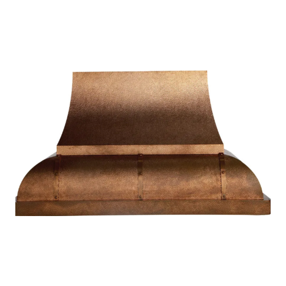
JCH/A1 DESIGNER SERIES
Read All Instructions Thoroughly Before Beginning Installation
WARNING - TO REDUCE THE RISK OF FIRE, ELECTRIC SHOCK,
OR INJURY TO PERSONS, OBSERVE THE FOLLOWING:
A. Installation work and electrical wiring must be done by qualified person(s)
in accordance with all applicable codes and standards, including fire-
rated construction. Switch power off at service panel and lock the service
disconnecting means to prevent power from being switched on accidentally
during installation.
B. When cutting or drilling into wall or ceiling, do not damage electrical wiring
and other hidden utilities.
C. Ducted fans must always be vented to the outdoors.
D. Sufficient air is needed for proper combustion and exhausting of gases
through the flue (chimney) of fuel burning equipment to prevent back
drafting. Follow the heating equipment manufacturer's guideline and
safety standards such as those published by the National Fire Protection
Association (NFPA), and the American Society for Heating, Refrigeration
and Air Conditioning Engineers (ASHRAE), and local code authorities.
E. ASHRAE residential ventilation standard 62.2 limits exhaust fans (total) to
a maximum of 15 CFM per 100 square feet of occupiable space, unless a
back drafting test is performed or make-up air is provided. Consult a local
HVAC engineer for make-up air evaluation.
WARNING - TO REDUCE THE RISK OF FIRE, USE ONLY METAL
JCH/A1 0611A
WALL MOUNT HOOD
DUCTWORK
Page 1
U L
C
US
R
Advertisement

Related Manuals for Vent-a-Hood JCH/A1 DESIGNER SERIES


Summary of Contents for Vent-a-Hood JCH/A1 DESIGNER SERIES
-
Page 1: Installation Instructions
Read and Save These Instructions All Hoods Must Be Installed By A Qualified Installer INSTALLATION INSTRUCTIONS JCH/A1 DESIGNER SERIES WALL MOUNT HOOD Read All Instructions Thoroughly Before Beginning Installation WARNING - TO REDUCE THE RISK OF FIRE, ELECTRIC SHOCK, OR INJURY TO PERSONS, OBSERVE THE FOLLOWING: A. - Page 2 20 feet, increase the duct diameter by one inch for every ten feet of duct. A 90 degree elbow is equal to 5 feet of duct. Using Vent-A-Hood roof jacks or wall louvers (back page) will ensure proper efficiency. Airflow must not be restricted at the end of the duct run. Do not use screen wire or spring-loaded doors on wall louvers or roof jacks.
-
Page 3: Installation Details
1”. This will allow the transition to engage 1” inside of duct. Consult the connection diagrams (on next page) for further details on exhaust outlet placement. Use duct tape to seal all joints. A complete listing of available Vent-A-Hood ducting materials is provided on the back page of this instruction sheet. - Page 4 Installation Details Continued Connection Diagram (36” - 48” Widths) 1 ¾” 1 ⁄ ” Wall Side Vent Hole Electrical 5 ¼” 6" Outlet Centerline Of Hood 300 CFM B100 Single Blower (Front View) (Top View) Connection Diagram (36” - 48” Widths) 5 ½”...
- Page 5 Installation Details Continued 5) Remove the shipping tape that is securing the E-Z Clean shield(s) inside the hood. Remove the E-Z Clean shield(s) by lightly pulling it toward the front of the hood. Gently close the back draft damper(s) from the top side of the hood. To remove the blower housing(s), unsnap the suitcase latches (one on each side of the housing).
- Page 6 Installation Details Continued 11) FOR BACK VENTING APPLICATIONS ONLY. IF NOT BACK VENTING, PROCEED DIRECTLY TO STEP 12. Note: Wall studs may interfere with back venting installations. Additional framing may be required. It is necessary to cut a duct access hole in the wall prior to installing the hood. To accomplish this, first remove and set aside the duct cover that was previously installed in Step 8.
- Page 7 VENTING ACCESSORIES WALL LOUVER WALL LOUVER WALL LOUVER RECTANGULAR WALL LOUVER 8 ⁄ ” 13” 11” 8 ½” 10” Back Back Back 6” 11” View View View 3 ¼” 7” 13” 6” 8” 1 ½” Flange 1 ½” Flange 1 ½” Flange MODEL DESCRIPTION MODEL...
Need help?
Do you have a question about the JCH/A1 DESIGNER SERIES and is the answer not in the manual?
Questions and answers