
Related Manuals for BURY UNI CarTalk Time


Summary of Contents for BURY UNI CarTalk Time
-
Page 1: Table Of Contents
UNI CarTalk Time Index Introductory information 1. General 2. Security guidelines 3. Scope of supply Installation of the hands-free car kit 4. Positioning and mounting 5. Connections on the electronics box 6. Installation of the loudspeaker switch box AC 5120 7. -
Page 2: Introductory Information
Congratulation on purchasing a BURY hands-free car kit. You have cho- sen a high quality product that is extremely easy to use. All aspects of BURY production through to sales and service are subject to strict qua- lity management according to DIN EN ISO 9001. All BURY hands-free car kits meet CE and e1 security standards. - Page 3 Faults Do not commission the device if you detect or assume a defect. In this case, contact a BURY specialised dealer or our hotline. Improper repair efforts can be dangerous for you. Therefore, only skilled personnel may perform inspections.
-
Page 4: Scope Of Supply
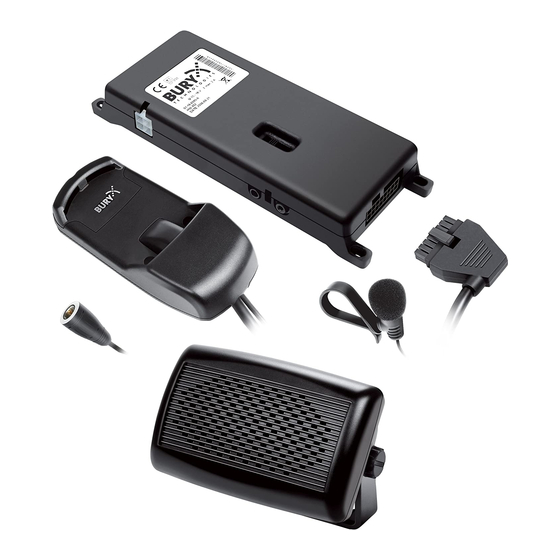
Installation of the hands-free car kit 3. Scope of supply 150 cm... - Page 5 The hands-free car kit (HFCK) is supplied with different combinations of components, depending on the sales regions (countries). The operating manual refers to all versions. Description of the components: 1) Electronics box (with and without integrated loudspeaker switch box) 2) Hang up cup for connection sets, including micro SD card slot and antenna connections for GPS (satellite detection) and GSM (telephone reception) 3) Fixing screws for electronics box, rider, assembly ring and blind plug...
-
Page 6: Positioning And Mounting
Installation of the hands-free car kit 4. Positioning and mounting Step 1: First of all, please choose the most convenient position for the hang-up cup in your vehicle by checking different positions in the vehicle. A connection set is inserted into this hang up cup, e.g. a UNI Take&Talk mobile holder that fits your mobile. - Page 7 In order to be able to use a mobile holder, you require approx. 10cm above the hang up cup and approx. 5cm on the left side to be able to insert and/or take out the memory card. Important: When positioning the monitor please take care that the monitor does not impair the view onto the road, that it will not be installed in the impact zone of the passenger compartment (amongst others in the airbag inflation zones) and that cables may be laid without any problems.
- Page 8 Installation of the hands-free car kit Step 2: To produce an electronic log, position data is required from your vehi- cle. This is provided via NAVSTAR GPS, a global navigation satellite sy- stem for determining position and timing, and is received by a GPS re- ceiver.
- Page 9 The end of the cable with the small plug is ideally suited for placing through small openings in the dashboard area. This facilitates a practi- cally invisible installation of the cable. Take the length of the cable into account and make sure that it is of sufficient length to reach the inten- ded location of the electronics box.
- Page 10 Installation of the hands-free car kit Step 4: A GSM antenna is not included in the scope of delivery. However you will require this, as your mobile may no longer have GSM reception af- ter a short time when is in the mobile holder. A separate GSM antenna improves the reception of your mobile phone, as it can be installed in various positions in or on the vehicle according to the type and design.
-
Page 11: Connections On The Electronics Box
5. Connections on the electronics box The additional components of the hands-free car kit are connected to the electronics box. The following connections are provided: Connection options: Power supply Voice output: internal loudspeaker switch box (depending on version) External loudspeaker Microphone Hang-up cup (basePlate) 1 - Power supply... - Page 12 Installation of the hands-free car kit 2 and 3 - Voice output of the hands-free car kit Version 1: Refer to separate chapter: Installation of the audio switch box AC 5120 Version 2: With version 2, this connection remains unused. Version 3: The cable (scope of supply no.
- Page 13 4 - Microphone This is where you plug in the microphone jack. After connection 3 has already been occupied use the rider. This ensures that neither of the jacks is able to loosen as a result of vibrations. 5 - Hang up cup Please plug in the molex plug of the hang up cup in this socket.
- Page 14 Use with vehicle loud speaker - with integrated loud speaker switch box - with external switch box AC 5120 - with external BURY loud speaker Use of vehicle loud speaker - with integrated loud speaker switch box - with external switch box AC 5120 Carry out a test call to check the volume and change the volume setting as required before you reattach facings to the vehicle.
-
Page 15: Installation Of The Loudspeaker Switch Box Ac 5120
If your car radio doesn‘t have this function, then the signals will be suppressed by the speaker switch box. You can use the AC 5120 through the connections that your BURY hands free car kit offers, which guarantee voltage supply via molex plugs and also have a speaker output. - Page 16 Installation of the hands-free car kit Now disconnect the (a) and/or the (b) loudspeaker connector from the speaker socket on the radio at the back. Connect this connector with the suitable socket (3) on the AC 5120. Now con- nect the plug (4) with the radio. Depending on the switcher position (5), the voice of your conversation partner will be fed back through either the front right speaker, the front left speaker, or through both of the front lou- dspeakers.
- Page 17 Different connections of the ISO plug on the radio The layout of the pins on the ISO plug used in a car depends on the type of car. Before using the switch box, you should make sure that the connections are correct in order to prevent possible damage to the device.
- Page 18 Installation of the hands-free car kit In the operating manual of the radio device, you can find the pin assignment for the “mute” signal. This signal can occur on one of three cables marked with “mute1”, “mute2”, or “mute3”. mute 1 mute (yellow) mute 2 radio device...
-
Page 19: Installation Instructions For The Fuses
7. Installation instructions for the fuses If you install the hands-free kit without the AC 5120 switch box then the power supply must be secured with a fuse in the way described below. Please cut through the red, the black and the blue cable by means of a wire cutter or scissors. Now insert the two endings of the red cable resulting from the cut into one of the binders, then close it. -
Page 20: Operating Guidelines
If you don’t want to receive a permanent visual display via the LEDs, then you can choose a different setting using BURY Time Suite PC- Software and deactivate the LEDs. After setting and/or changing the... -
Page 21: Automatic Switch Off
9. Automatic switch off The hands-free car kit is active as long as the motor and/or the ignition of the vehicle is turned on. If you turn off the motor, the collected log book data will be transferred onto the micro SF card, if this is inserted. -
Page 22: Electronic Driver's Logbook
USB interface When you open the BURY Time Suite for the first time, you must set an administrator and enter a user name and password. If you use the software on a private basis then this will be no problem. If you use the software in a network and several people need to be able to work with it, than the roles of the persons (who is the administrator) should be defined in advance. - Page 23 Important: Format the memory card under the configuration section - UNI CarTalk Time card. Then generate some example log book data by travelling a few kilometres with the vehicle and chan- ging the journey mode several times. When the data is read in, the memory card will be firmly alloca- ted to a vehicle.
- Page 24 Operating guidelines Using the BURY Time Suite you can also transfer data about danger zones onto the memory card and release the warning function for this, under the configuration section. Note: The danger zones that are included are provided by the third party company Eifrig Media.
-
Page 25: Further Information
Further Information 11. Service In case of general or technical queries, suggestions and comments, please do not hesitate to contact our team at any time: BURY GmbH & Co. KG Robert-Koch-Straße 1-7 32584 Löhne Hotline: +49(0)180 5 - 842 468*...
Need help?
Do you have a question about the UNI CarTalk Time and is the answer not in the manual?
Questions and answers