Table of Contents
Advertisement
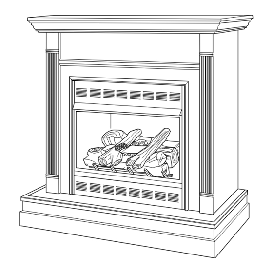
UNVENTED (VENT-FREE) GAS FIREPLACE
OWNER'S OPERATION AND INSTALLATION MANUAL
PFS
Shown with optional cabinet mantel
and hearth base accessories.
REMOTE CONTROL GAS FIREPLACE SYSTEMS
WARNING: If the information in this manual is not
followed exactly, a fire or explosion may result causing
property damage, personal injury or loss of life.
— Do not store or use gasoline or other flammable
vapors and liquids in the vicinity of this or any other
appliance.
— WHAT TO DO IF YOU SMELL GAS
• Do not try to light any appliance.
• Do not touch any electrical switch; do not use any
phone in your building.
• Immediately call your gas supplier from a neighbor's
phone. Follow the gas supplier's instructions.
• If you cannot reach your gas supplier, call the fire
department.
— Installation and service must be performed by a quali-
fied installer, service agency or the gas supplier.
INSTALLER: Leave this manual with the appliance.
CONSUMER: Retain this manual for future reference.
For more information, visit www.fmiproducts.com
®
US
CGEFP33NRC AND CGEFP33PRC
Advertisement
Table of Contents

Related Manuals for Comfort Flame CGEFP33NRC


Summary of Contents for Comfort Flame CGEFP33NRC
- Page 1 OWNER’S OPERATION AND INSTALLATION MANUAL ® Shown with optional cabinet mantel and hearth base accessories. CGEFP33NRC AND CGEFP33PRC REMOTE CONTROL GAS FIREPLACE SYSTEMS WARNING: If the information in this manual is not followed exactly, a fire or explosion may result causing property damage, personal injury or loss of life.
-
Page 2: Table Of Contents
TABLE OF CONTENTS Safety ..............2 Troubleshooting ..........26 Product identification ........... 4 Specifications ............ 30 Local Codes............4 Wiring Diagram ..........30 Unpacking............5 Technical Service..........30 Product Features ..........5 Replacement Parts ..........30 Air for Combustion and Ventilation ...... 5 Service Hints ............. - Page 3 SAFETY Do not place clothing or other Continued flammable material on or near the appliance. Never place any DANGER: Carbon monoxide objects on the heater. poisoning may lead to death! Fireplace and screen become Carbon Monoxide Poisoning: Early signs very hot when running fireplace. of carbon monoxide poisoning resemble the Keep children and adults away flu, with headaches, dizziness or nausea.
-
Page 4: Product Identification
SAFETY PRODUCT IDENTIFICATION Continued 4. This fireplace shall not be installed in a bedroom or bathroom. 4-Piece 5. Do not use this fireplace as a wood-burn- Log Set ing fireplace. Use only the logs provided with the fireplace. 6. Do not add extra logs or ornaments such as pine cones, vermiculite or rock wool. -
Page 5: Unpacking
LOCAL CODES SAFETY DEVICE Continued This fireplace has a pilot with an Oxygen Deple- tion Sensing (ODS) safety shutoff system. The ODS/pilot is a required feature for vent-free State of Massachusetts: The installation room heaters. The ODS/pilot system shuts off must be made by a licensed plumber or the fireplace if there is not enough fresh air. - Page 6 AIR FOR COMBUSTION whose volume is less than 50 cubic feet per 1,000 Btu per hour (4.8 m per kw) of the ag- AND VENTILATION gregate input rating of all appliances installed Continued in that space and an unconfined space as a Exhaust fans, fireplaces, clothes dryers and space whose volume is not less than 50 cubic fuel burning appliances draw air from the house...
- Page 7 AIR FOR COMBUSTION VENTILATION AIR AND VENTILATION Ventilation Air From Inside Building This fresh air would come from an adjoining Continued unconfined space. When ventilating to an Direct-vent draws combustion air from the adjoining unconfined space, you must provide outdoors and vents to the outdoors. two permanent openings: one within 12"...
-
Page 8: Installation
INSTALLATION Note: Your fireplace is designed to be used in zero clearance installations. Wall or framing NOTICE: This heater is intended material can be placed directly against any for use as supplemental heat. exterior surface on the rear, sides or top of your fireplace, except where standoff spacers Use this heater along with your are integrally attached. -
Page 9: Installation Clearances
INSTALLATION Continued Trim Hanging Screws Hanging Notches on Trim Assembled Trim Figure 5 - Installing Hood to Firebox Figure 7 - Attaching Trim to Fireplace ASSEMBLING AND ATTACHING INSTALLATION CLEARANCES BLACK TRIM WARNING: Maintain the IMPORTANT: If you are recessing the firebox in a wall, do not attach trim at this time. - Page 10 INSTALLATION 7. Break off nailing flanges (see Figure 11) with hammer or pliers. Continued 8. Place cardboard or other protective mate- CONVENTIONAL FIREPLACE rial on top of hearth base. Carefully set INSTALLATION fireplace on protective material, with back of fireplace inside mantel opening. Conventional installation of this fireplace involves installing fireplace along with the 9.
- Page 11 INSTALLATION 2. If using blower, install duplex outlet to the right support bracket in the bottom of firebox Continued (see Figure 14). See Accessories, page 31. BUILT-IN FIREPLACE If not using blower, go to step 7. INSTALLATION 3. Route wires from electrical box through smallest hole in outer casing using strain Built-in installation of this fireplace involves relief fitting provided (see Figure 14).
- Page 12 INSTALLATION WARNING: Do not allow any Continued combustible materials to overlap 11. Plug electrical cord into electrical outlet the firebox front facing. installed in step 2 if using blower. 12. Carefully insert fireplace into rough IMPORTANT: Noncombustible materials such opening. as brick, tile, etc.
- Page 13 INSTALLATION Continued Mantel Shelf Wall board or facing material (above 10" firebox) may be of 8" combustible material, including decorative 6" mantel ornaments or " other similar projec- tions off of the facing material. Framing Material Noncombustible Material May Project Off this Surface above Firebox the Firebox...
- Page 14 INSTALLATION Continued For propane/LP units, the installer must contaminants. This keeps them from going supply an external regulator. The external into fireplace gas controls. If sediment trap regulator will reduce incoming gas pressure. is not installed or is installed wrong, fireplace You must reduce incoming gas pressure to may not run properly.
- Page 15 INSTALLATION Continued CONNECTING FIREPLACE TO GAS 7. Replace log base assembly back into fireplace. Feed flexible gas line into fire- SUPPLY place base area while replacing log base Installation Items Needed assembly. Make sure the entire flexible • 5/16" hex socket wrench or nut-driver gas line is in fireplace base area.
- Page 16 INSTALLATION Test Pressures Equal To or Less Than 1/2 PSIG (3.5 kPa) Continued 1. Close equipment shutoff valve (see Fig- CHECKING GAS CONNECTIONS ure 22). 2. Pressurize supply piping system by either WARNING: Test all gas pip- opening propane/LP supply tank valve ing and connections, internal for propane/LP gas or opening main gas and external to unit, for leaks...
-
Page 17: Safety Information
INSTALLATION 1. Locate pegs on bottom of back log (#1). Slide these pegs into holes in grate base Continued behind burner (see Figure 25). PRESSURE TESTING FIREPLACE GAS 2. Place base of middle log (#2) in U-shaped CONNECTIONS slots of grate base in front of back log. 1. - Page 18 INSTALLATION Continued 3. Locate the notches in bottom of front Crossover Crossover log (#3). Place front log on grate fingers. Log (#4) Log (#5) Make sure notches of front log line up with grate fingers (see Figure 27). 4. Place left crossover log (#4) across logs #1, #2 and #3 fitting holes on bottom of log #4 Pins onto pin on front and middle logs as shown...
- Page 19 INSTALLATION Continued INSTALLING BATTERIES IN Installing Cover Plate Onto Remote Receiver 1. Locate and remove cover plate from REMOTE CONTROL AND RECEIVER packaging. 2. Make sure sliding selector switch fits over WARNING: Make sure your switch on receiver. selector switch is in OFF posi- 3.
-
Page 20: Operation
OPERATION LIGHTING INSTRUCTIONS FOR YOUR SAFETY READ BEFORE LIGHTING WARNING • If fireplace has glass doors, WARNING: If you do not fol- never operate this heater with low these instructions exactly, glass doors closed. If you op- a fire or explosion may result erate heater with doors closed, causing property damage, per- heat buildup inside fireplace... - Page 21 OPERATION 9. Slightly push in and turn control knob coun- terclockwise to the ON position. Continued 10. Press the on/off key on the remote control 3. Set remote selector switch in the AUTO to turn on appliance main burner. Wait at position (see Figure 32).
- Page 22 OPERATION OPERATING REMOTE CONTROL Continued WARNING: Fireplace can HAND-HELD turn on suddenly. Keep away REMOTE OPERATION from burner. BATTERIES After lighting pilot, let pilot flame burn for about one minute. Slide remote selector switch to WARNING: Make sure your REMOTE position. You can now turn the selector switch is in OFF posi- burner on and off with the remote.
- Page 23 OPERATION To activate this function, press THERMOSTAT button until the word SMART appears to the Continued right of temperature bulb graphic on display. FLAME HEIGHT Use UP/DOWN arrow button to set desired This function allows you to control the height room temperature.
-
Page 24: Inspecting Burners
INSPECTING BURNERS MAIN BURNER Periodically inspect all burner flame holes with Check pilot flame pattern and burner flame the fireplace running. All slotted burner flame patterns often. holes should be open with yellow flame present. PILOT FLAME PATTERN All round burner flame holes should be open Figure 43 shows a correct pilot flame pattern. -
Page 25: Cleaning And Maintenance
CLEANING AND 4. Check injector holder located at the end of burner tube again. Remove any large MAINTENANCE particles of dust, dirt, lint or pet hair with a soft cloth or vacuum cleaner nozzle. WARNING: Turn off fireplace 5. Blow air into the primary air holes on the and let cool before cleaning. -
Page 26: Troubleshooting
TROUBLESHOOTING WARNING: Turn off heater and let cool before servicing. Only a qualified service person should service and repair heater. CAUTION: Never use a wire, needle or similar object to clean ODS/pilot. This can damage ODS/pilot unit. Note: All troubleshooting items are listed in order of operation. OBSERVED PROBLEM POSSIBLE CAUSE REMEDY... - Page 27 TROUBLESHOOTING Continued OBSERVED PROBLEM POSSIBLE CAUSE REMEDY ODS/pilot lights but flame 1. C o n t r o l k n o b n o t f u l l y 1. Press in control knob fully goes out when control knob pressed in is released 2.
- Page 28 TROUBLESHOOTING Continued OBSERVED PROBLEM POSSIBLE CAUSE REMEDY Slight smoke or odor during 1. Not enough air 1. Check burner for dirt and initial operation debris. If found, clean burner (see Cleaning and Moisture/condensation no- Maintenance, page 25) ticed on windows 2.
- Page 29 TROUBLESHOOTING Continued WARNING: If you smell gas • Shut off gas supply. • Do not try to light any appliance. • Do not touch any electrical switch; do not use any phone in your building. • Immediately call your gas supplier from a neighbor’s phone. Fol- low the gas supplier’s instructions.
-
Page 30: Specifications
SPECIFICATIONS CGEFP33NRC CGEFP33PRC • Rating (Variable): 23/33,000 Btu/Hr • Rating (Variable): 23/33,000 Btu/Hr • Gas Type: Natural Gas • Gas Type: Propane/LP Gas • Ignition: Piezo • Ignition: Piezo • Pressure Regulator Setting: 3.5" W.C. • Pressure Regulator Setting: 7.9" W.C. -
Page 31: Accessories
ACCESSORIES CABINET MANTEL AND FULL NOTICE: All accessories may HEARTH BASE not be available for all fireplace W32TU - Unfinished, Traditional models. W32TO - Medium Oak, Traditional W32CO - Dark Oak, Classic Purchase these accessories from your local W32DO - Medium Oak, Traditional/Dentil dealer. -
Page 32: Parts
PARTS MODELS CGEFP33NRC AND CGEFP33PRC www.fmiproducts.com 121308-01J... - Page 33 PARTS This list contains replaceable parts used in your fireplace. When ordering parts, follow the instructions listed under Replacement Parts on page 30 of this manual. PART NO. DESCRIPTION QTY. 111625-03 Middle Log • • 111625-04 Rear Log • • 111625-02 Front Log •...
- Page 34 PARTS FIREBOX CGEFP33NRC AND CGEFP33PRC www.fmiproducts.com 121308-01J...
- Page 35 PARTS FIREBOX CGEFP33NRC AND CGEFP33PRC This list contains replaceable parts used in your fireplace. When ordering parts, follow the instructions listed under Replacement Parts on page 30 of this manual. NO. PART NO. DESCRIPTION QTY. 101357-03 Top Outer Casing Outer Casing...
-
Page 36: Warranty
WARRANTY KEEP THIS WARRANTY Model (located on product or identification tag) _____________________________ Serial No. (located on product or identification tag) __________________________ Date Purchased __________________________ Keep receipt for warranty verification. FMI PRODUCTS, LLC LIMITED WARRANTIES New Products Standard Warranty: FMI PRODUCTS, LLC warrants this new product and any parts thereof to be free from defects in material and workmanship for a period of two (2) years from the date of first purchase from an authorized dealer provided the product has been installed, maintained and operated in accordance with FMI PRODUCTS, LLC’s warnings and instructions.
Need help?
Do you have a question about the CGEFP33NRC and is the answer not in the manual?
Questions and answers