Table of Contents
Advertisement
Quick Links
Advertisement
Table of Contents

Related Manuals for Tennant Castex BR-2000


Summary of Contents for Tennant Castex BR-2000
- Page 1 BR-2000 Battery Burnisher Operator and Parts Manual Model No.: 607418 CASTEX INCORPORATED 12875 RANSOM STREET HOLLAND MI 49424 U.S.A. A TENNANT COMPANY 1–800-522–7839 616-786–2330 608265 FAX: 1–800–678–4240 Rev. 00 (07-99) CUSTOMER SERVICE: 1–800-964–9644 Home Find... Go To..
-
Page 2: Table Of Contents
E1999 Tennant Company Printed in U.S.A. manufacturer subsidiaries. Castex is a registered United States trademark of Tennant Company. This machine will provide excellent service. However, the best results will be obtained at minimum costs if: The machine is operated with reasonable care. -
Page 3: Safety Precautions
OPERATION 5. When servicing machine: SAFETY PRECAUTIONS – Avoid moving parts. Do not wear loose jackets, shirts, or sleeves. – Block machine tires before jacking This machine is suited to burnish smooth floors in an machine up. indoor environment and is not constructed for any –... -
Page 4: Machine Components
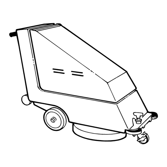
OPERATION MACHINE COMPONENTS 1. Control Console 8. Small Rear Wheels – for tilting back machine to install pad. 2. Control Grips 9. Pad Pressure Adjustment Knob 3. Machine ON/OFF Switch 10. Wall Rollers 4. Power ON Indicator Light 11. Front Caster 5. -
Page 5: Machine Installation
OPERATION MACHINE INSTALLATION MACHINE UNCRATING Carefully check carton for signs of damage. Report damages at once to carrier. Batteries and battery charger are packaged separately. Battery installation must be accomplished after removing machine from crate. To uncrate your machine remove straps and carefully Fig. -
Page 6: Machine Setup
OPERATION MACHINE SETUP PRE–OPERATION CHECKS 1. Sweep the floor to remove particles and other debris. 2. Check battery meter charge level to ensure batteries are fully charged (See BATTERY CHARGING). 3. Check that a pad is installed. Fig. 4. 4. Before burnishing make sure floor is dry. ATTENTION: Make sure centerlock does not cross INSTALLING PAD thread or floor damage could occur. -
Page 7: Machine Operation
OPERATION MACHINE OPERATION FOR SAFETY: Do not operate machine unless operator manual is read and understood. 1. Adjust pad to correct pad pressure: With pad installed and caster wheel swung towards pad driver, rotate pad pressure adjustment knob clockwise until pad is not touching floor, (check by manually spinning pad;... -
Page 8: While Operating Machine
OPERATION CHARGER SPECIFICATIONS: OUTPUT VOLTAGE - 24 VOLTS OUTPUT CURRENT - 25 AMPS AUTOMATIC SHUTOFF CIRCUIT FOR DEEP CYCLE BATTERY CHARGING NOTE: For optimum machine operation, keep batteries charged at all times. Never let batteries set in a discharge condition. ATTENTION: Do not continue to run machine when battery meter needle is in the red zone, battery damage will result. -
Page 9: Maintenance
OPERATION 9. Recheck battery fluid level after charging. If needed, add distilled water to bring level of fluid to bottom of sight tubes. Be certain to replace cell caps securely and to wipe off the top of batteries with a clean cloth. MAINTENANCE To keep machine in good working condition, simply follow machines daily, weekly and monthly... -
Page 10: Battery Maintenance
OPERATION ATTENTION: Do not transport machine tilted back BATTERY MAINTENANCE on small rear wheels. Battery acid may run out the top of batteries. Battery acid can cause severe burns on contact with skin. WARNING: Batteries emit hydrogen gas. Explosion or fire can result. Keep sparks and 3. -
Page 11: Trouble Shooting
OPERATION TROUBLE SHOOTING PROBLEM CAUSE SOLUTION No power, nothing runs. Faulty ON/OFF switch Contact Service Center. Batteries need charging. See Battery Charging Battery(s) faulty. Replace battery(s) Loose battery cable. Tighten loose cables. Batteries are not connected correctly. See Battery Installation. Pad motor does not run. -
Page 12: Parts List
PARTS LIST CHASSIS ASSEMBLY BR-2000 (07–98) Home Find... Go To.. - Page 13 PARTS LIST CHASSIS ASSEMBLY PART # DESCRIPTION QTY. PART # DESCRIPTION QTY. 607818 CHASSIS, BLUE 15752.14 WASHER, LOCK 25660 AXLE, FRONT 14501 DGRIP, HANDLE 140015 WASHER, LOCK 200823 DSWITCH 140223 SCREW 19417 DLIGHT, INDICATOR 25656 WHEEL 130738 DMETER, PAD PRESSURE 103071 BEARING 25647...
- Page 14 PARTS LIST BRUSH DRIVE GROUP BR-2000 (07–98) Home Find... Go To..
- Page 15 PARTS LIST BRUSH DRIVE GROUP PART # DESCRIPTION QTY. PART # DESCRIPTION QTY. DMOTOR, 24V 607816 COVER, BATTERY, BLUE 130479 D CARBON BRUSH 140829 SCREW 512003 DGASKET 140932 LATCH (ASM.) 25675 140539 NUT, KEP 140628 26656.BK GUARD, PAD DRIVER 25732 WASHER, FLAT DGASKET 25675...
-
Page 16: Electrical Diagram
ELECTRICAL DIAGRAM BR-2000 (07–98) Home Find... Go To..
Need help?
Do you have a question about the Castex BR-2000 and is the answer not in the manual?
Questions and answers