DRAKE R-4C Instruction Manual
Hide thumbs
Also See for R-4C:
- Instruction manual (36 pages) ,
- Instruction manual (42 pages) ,
- Instruction manual (36 pages)
Table of Contents
Advertisement
Quick Links
Download this manual
See also:
Instruction Manual
Advertisement
Table of Contents

Subscribe to Our Youtube Channel
Related Manuals for DRAKE R-4C


Summary of Contents for DRAKE R-4C
-
Page 2: Table Of Contents
TABLE OF CONTENTS Page CHAPTER I INTRODUCTION ..... . . l - l l - l . GENERAL DESCRIPTION l - l 1 - 2 . - Page 3 TABLE OF CONTENTS (continued) Page 3 - 1 3 . S'METER 3 - 1 4 . PHONE-JACK. S'METER ZERO. 3-15. 3 - 1 6 . B A S I C CONTROL SETTINGS 3- 5 3 - 17. SSB RECEPTION 3 -6 3 - 1 8 .
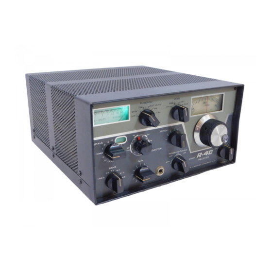
- Page 4 LIST OF ILLUSTRATIONS Figure Page 1-1. R-4C RECEIVER 2-1. VIEWING ANGLE OPTIONS. 2-2. REAR CHASSIS CONTROLS ..2 - 5 CONNECTING TR--4C. 2-3. 2 - 3 FRONT PANEL CONTROLS..
-
Page 5: Chapter I
CHAPTER I INTRODUCTION 1.1. GENERAL DESCRIPTION. the frequency range of the receiver. The R-4C Receiver is a triple conversion super- 1-2. MANUAL COVERAGE. heterodyne receiver designed for optimum recep- tion of all types of amateur radio communications. This manual is presented in 5 chapters and is ar-... -
Page 6: Specifications
SPECIFICATIONS Frequency Coverage Covers 3.5 to 4.0 MHz, 7.0 to 7.5 MHz, 14.0 to 14.5 MHz, 21.0 to 21.5 MHz, and 28.5 to 29.0 MHz. Accessory Coverage: 15 accessory crystal sockets are provided. Coverage of any additional 500 kHz ranges between 1.5 and 30 MHz (except between 5.0 and 6.0 MHz) can be added by installing accessory crystals. -
Page 7: Chapter Ii Installation
120 V position. Operation of the receiver from 240 V with the switch in the 120 V position will The location of the R-4C is not critical, as long as cause serious damage. allowance is made for adequate air circulation. -
Page 8: Mute
PTO dial. The R-4C is shipped with a shorted phono plug in this jack so that the 2-14. ACCESSORY CRYSTALS. lamp will light. When the R-4C is used with the T-4XC transmitter, remove the shorted phono By inserting the appropriate crystals in the acces-... -
Page 9: Noise Blanker
R-4/R-4B. The adjust- The 4-NB mounts on the four plastic stand-offs ment on the R-4C is C59 located on a PC board on which are on the metal shields on either side of the the top of the R-4C chassis (see figure 5-l). - Page 10 Table 2- 1. Crystal Frequency Chart FREQUENCY FREQUENCY RANGE CRYSTAL BAND RANGE CRYSTAL BAND 1.5 - 12.6 1.5 - - 3.0 16.5 - - 1 17.0 27.6 21.0 2.0 - - 13.1 1.5 - - 3.0 17.0 - - 17.5 28.1 21.0 2.5 - 3.0...
-
Page 11: Chapter Iii Operation
PASSBAND TUNING control to 12 o’clock. sory AM 8 pole filter can be installed in the internal b. Tune the R-4C to zero beat with the nearest accessory filter socket in place of the 150 Ohm 25 kHz calibrator signal. -
Page 12: Front Panel Controls
FRONT PANEL CONTROLS 8. PASSBAND TUNING Control: Adjusts the 1. S Meter: Indicates relative signal strength. positioning of the BFO in SSB and CW modes. Calibrated in S units from 1 to 9. Above 9 the scale is calibrated in decibels. 9. -
Page 13: B A N D
stationary and rotate the knob skirt until the knob pointer indicates the position of the BFO dial displays the correct frequency. with respect to the passband. The longest line in- dicates the passband width of the 2.4 kHz filter used in the SSB mode. The dot at the left end of 3-6. -
Page 14: Agc
The S meter zero control is on the rear panel of the the unwanted carrier is removed by the notch filter. R-4C. It may be used to set the S meter needle to Since the notch filter will remove the wanted car- S-l under no-signal conditions. -
Page 15: Ssb Reception
3-18 CW RECEPTION. f. Set AF GAIN knob to a comfortable level. g. Set PRESELECTOR control to center of band a. Make the basic control settings listed in para- segment marked on panel. After desired signal is graph 3-l6. tuned in, adjust for maximum S meter reading. b. -
Page 16: Rtty Reception
RTTY is possible to add up to 15 additional tuning ranges reception. (each 500 kHz wide) to the coverage of the R-4C. With the exception of the band from 5.0 to 6.0 Set PASSBAND TUNING to the RTTY region. -
Page 17: Theory Of Operation
CHAPTER IV THEORY OF OPERATION 4-1. GENERAL. kHz from V2. Gang tuning of the RF coils Tl and T2 and the premixer ouptut coils T3 and T4 is Refer to the block diagram figure 4-l and the used to maintain a fixed frequency relationship schematic diagram figure 5-3 as required for the among these variable circuit elements. -
Page 18: Second If System And Detectors
scale. Potentiometers R32 and R33 are used to set 4-6. SECOND IF SYSTEM AND DETECTORS. the bridge balance point, determining the zero ad- justment of the S Meter. The current characteristics The 50 kHz signal from T7C is coupled to the grid of the plate circuits of V2 and V4 are such that of V5 through the T-Notch filter T8 and its associ- line voltage variation does not affect the zero set-... -
Page 19: Maintenance
Careful consideration has been given in the design of the R-4C to keeping maintenance problems to a The R-4C has been designed so that tubes can be minimum. However, it is quite possible that some replaced without need for realignment. The best... -
Page 20: 50Khz Bfo And If Alignment
5-7. 50 kHz BFO AND IF ALIGNMENT. ward the front panel). The pointer on the knob should be at the nine o’clock position. If it isn’t, Apply signal of exactly 50.000 kHz to pin 2 of loosen the knob setscrew and position the knob V4 (6EJ7). - Page 21 Plug the 12.6 MHz crystal into one of the acces- inserted . sory crystal sockets. i. Turn off the R-4C, and remove the alignment Set the receiver right side up on the bench and resistors. turn the PRESELECTOR knob as far clockwise as possible.
- Page 22 Resistance Chart Table 5- 1. MEASURED AT PIN Type 0.01 5.5K 6BA6 6.5 K 6EJ7 100 K 6BE6 5.0M 0.01 5.5 K 16 K 1 2 K 6.5 K 4 2 K 6EJ7 6BA6 0.01 5.5K 6EJ7 680 K 2N5950 D:180 G:l K+ S:68...
Need help?
Do you have a question about the R-4C and is the answer not in the manual?
Questions and answers