Table of Contents
Advertisement
Quick Links
Advertisement
Table of Contents

Related Manuals for DRAKE SPR-4


Summary of Contents for DRAKE SPR-4
- Page 1 DRAKE MODEL SPR-4 COMMUNICATIONS RECEIVER TECHNICAL MANUAL...
-
Page 2: Table Of Contents
Table of Contents Fig. P a g e GENERAL DESCRIPTION Viewing Angle Options Features Front Pane1 Operating Controls Specifications Rear Controls & Connections Block Diagram INSTALLATION Top Alignment Adjustment Points Unpacking 2 . 1 Bottom Alignment Adjustment Points Location 2 . 2 SCC-4 Circuit Board Power Requirements 2 . -
Page 3: Features
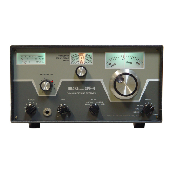
G E N E R A L D E S C R I P T I O N FEATURES The SPR-4 is an a11 solid-state communications receiver which can te programmed with accessory crystals to cover 150 kHz to 30 MHz. The SPR-4 receives AM, CW, SSB (Upper and lower and may be powered from 120 VAC, 240 VAC and 12 VDC. -
Page 4: Front Pane1 Operating Controls
Audio Output Power: 3 watts into 4 ohm load (less into higher imped- ance loads More than 60 dB below rated output. Hum and Noise: Calibration: Dial is accurate to better than _ + 1 kHz when calibrated to nearest 100 kHz calibration point. POWER CONSUMPTION: 18 watts on 120 V DC, or 240 V AC, and 6 watts 1 . -
Page 5: Rear Controls & Connections
Function Symbol Type lN270 Premixer Switch lN4148 RF Amplifier Protection lN4148 RF Amplifier Protection lN714 Zener Regulator B5G5 Power Supply Rectifier B5G5 Power Supply Rectifier B5G5 Power Supply Rectifier Z13B Zener Regulator lN714 Zener Regulator lN4148 AVC Switch CRl0 lN270 AVC Switch CRll lN4148... -
Page 6: Block Diagram
V I E W I N G A N G L E O P T I O N S F i g u r e 1 . -
Page 7: Installation
INSTALLATION UNPACKING Carefully remove the receiver from the shipping carton, and examine it If any damage is discovered, immediately noti- for evidence of damage. fy the transportation company that delivered the receiver. Be sure to keep the shipping carton and packing material, as the transportation com- pany will want to examine them if there is a damage claim. -
Page 8: Speakers
results . 50 to 100 feet long will give good An antenna kit (Mode1 AN-S) is available. For best single band performance, a half wave dipole or other resonant used . fed with unbalanced 50 ohm coaxial table, may be How- antenna , ever, Bands A and B require a long wire antenna. - Page 9 P O W E R 2.8.1 The power connector mates with both the AC and DC power cords . See “2 3 ” 2 . 8 . 2 F U S E The fuse holder must have the proper fuse installed for 120 or 240 V AC operation .
- Page 10 The SPR-4 audio amplifier may be used with an external audio source such as a tuner. The level of the external source must be approximately The received signals may be eliminated by volts into a 3 K load . turning the RF GAIN control counter-clockwise or by removing the mute plug 2.8.9 DIAL LAMPS The DIAL LAMPS switch may be used to tum off the three dial...
-
Page 13: Operation
OPERATION Refer to Figure 3 for the location of the operating controls. OPERATING CONTROLS The S-meter indicates the relative level of the received signals . The crystal selector switch selects the band determining crystals . The top line of the dial sector reads the lowest frequency of each band in MHz, the middle line indicates the approximate position for tuning the preselector and the bottom line indicates the proper sett- ing of the range switch. -
Page 14: Dia1 Calibration
knob from the off position moves the rejection notch across the re- ceiver pass band . The accessory switch turns on the S-NB Noise Blanker and the SCC-4 Crystal Calibrator if they are installed. The 5-NB and the SCC-4 are off in the NORM position. - Page 15 -13-...
-
Page 16: Principles Of Operation
P R I N C I P L E S O F O P E R A T I O N 4 . 1 LOOP AM PLIFIER On Bands A and B Q1 amplifies signals from the loop antenna and feeds one gate of the R.F. -
Page 17: Second Mixer
to one gate of the premixer, Q5 through C26 and R15. The P.T.O. drives the other gate of Q5 through R25 and C76. The P.T .O. is tuneable from 4955 kHz to 5455 kHz. The output of Q5 is tuned by the components associated with S4F, S4R, S8F, S8R and drives the 1st mixer through T6, S6R, C99 and C96. -
Page 18: Avc System
AVC SYSTEM The AVC threshold is established by the setting of R111, the R.F. gain is normally operated fully This applies approx- control. R111 clockwise . imately +2 volts to the AVC line through R104, R100 and CR15 with no received signal. -
Page 19: Pictorial Wiring Diagram
-17-... -
Page 20: Circuit Board
-18-... -
Page 21: Alignm Ent
A L I G N M E N T 5 . 1 REMOVING COVERS Remove the AL-4 Loop Antenna if it is in use. Remove the top three screws on each side of the SPR-4 and remove the top cover by pulling up on the rear and then on the front of the cabinet. -
Page 22: Bottom View - Circuit Board
An accessory crystal for reception of W W V standard frequency trans- mission that is most reliably received in your area. See Page 33 to determine crystal frequency required. This crystal is not required if SPR-4 does not have an SCC-4 Crystal Cal- ibra tor . - Page 23 minal on the R.F. amplifier board at the left top corner, looking into the bottom of the SPR-4 and front pane1 facing you. This terminal has coax connected to it . Care should be taken not to short this point to ground because Q4 will be ruined, Preset the balance pot on the 1st mixer board fully clockwise.
-
Page 24: Loop Amplifier Circuit Board
and mixer trimmers for maximum AVC deflection. Detune T6 by grasp- ing a metal screwdriver shaft and touching it to the rotor contact of S4R, and tune the rear H band injection trimmer for maximum AVC deflection. Detune T1 by touching the rotor contact of S8F and tune the front H band injection trimmer for maximum AVC deflection. -
Page 25: Rf Amplifier Circuit Board
the notch control at 12 o’clock and adjust the main tuning knob for max- Altemately adjust the notch control imum AVC voltage ( positive going and the notch depth control, R57, for maximum AVC voltage (positive going 5.3.5 S-METER ADJUSTMENT Tune in a 10,000 microvolt signal on 7.2 MHz LSB and looking into the top of the chassis with the front panel facing you, adjust R73, the left control on the S-meter circuit board for + 4.5 volts on the middle top ter-... -
Page 26: Accessories
ACCESSORIES MCDEL SCC-4 CRYSTAL CALIBPATOR GENERAL DESCRIPTION 6 . 1 . 1 The SCC-4 is a 100 kHz crystal controlled oscillator that injects into the receiver a harmonic every 100 kHz throughout the SPR-4 frequency cover- age . 6.1.2 INSTALLATION Remove the top row of 3 screws on each side of the SPR-4 cabinet. - Page 27 puls e. Between noise pulses full receiver gain is restored . Receiver AVC is affected only by the desired signal and not by noise when the 5-NB is in use. The 5-NB is most effective on strong, periodic impulse noise such as ignition noise. 6.2.2 INSTALLATION install the 5-NB, remove the top row of three screws on each side of the SPR-4 Receiver cabinet.
-
Page 28: Radio Teletype Adaptor
reverse biased and turned “off”. With the series gate “off”, the signal path through the 5-NB is broken and reception is blanked for the dura- tion of the interferring noise pulse. The 5-NB is turned on by the acces- sory switch in the SPR-4 which removes the ground from Pin 1 of P-5 and allows Q3 in the 5-NB to oscillate permitting signals to mix in the 5-NB balanced mixer and eventually operates the series gate. -
Page 29: Premixer Output Circuit Board
When the mode switch is in the AM or USB position, shorting the RTTY jack will have no effect. 6.3 .2 INSTALLATION This modification should be made by a competent technician. If you need help or want the RY-4 to be installed by one of our factory authorized service centers or by the factory service technicians , please call or write our Customer Service Department . -
Page 30: Transceive Adaptor
CIRCUIT DESCRIPTION 6 . 3 . 4 The BF0 is shifted in frequency for RTTY reception by shunting a capacitor across T17 with an electronic switch . Transistor Q2 electronically switches C2 across T17, and Q3 switches C3. Switch S14R connects the collector of Q1 to the base of Q3 in CW and to the base of Q2 in LSB . -
Page 31: 2Nd Mixer Circuit Board
Late SPR-4’s have a 12 K 1/2 watt resistor between T-6 and the pins . pre- Cut the resistor lead from T-6 and remove the resistor. Route mixer board the coax cable along the wiring harness and install the phono fitting on the end of the cable in the large hole near the center of rear chassis apron a s The nut and the flat washer should be on the outside... -
Page 32: 1St If Amplifier Circuit Board
6.4.4 CIRCUIT DESCRIPTION The transceive switch on the T-4/T-4B/T-4X/T-4XB Transmitter controls the TA-4 by applying a negative or positive D.C. potential to the injec- tion c a b l e . When the transceive switch on the transmitter is in SPOT position, no D potential is applied to the injection cable and the .C . -
Page 33: Avc Alterations
S PR-4 CONTROL OR SWITCH T-4XB Band or Range switch 3 . 5 - - - Crys tal switch 3 . 5 - - - Function Mode - - - 3 o’clock Audio Gain - - - Transceive spot - - - Anti -Vox Full clockwise - - -... -
Page 34: S -Meter Circuit Board
6.5.3 AVC OFF ALTERATION The AVC may be remotely turned off in SPR-4’s with serial numbers above 1,000. This is obtained by altering connections to two terminals on the power supply board One of these two terminals has two white/bIue wires Cut the jumper from these two terminals and connect an attached . -
Page 35: Notch Filter Circuit Board
S P R - 4 A C C E S S O R Y C R Y S T A L C H A R T FREQ . OPERATING FREQ. OPERATING FREQ. CRYSTAL CRYSTAL FREQ. i n M H z . i n M H z . -
Page 36: Service Data On Accessories
SERVICE DATA FOR SPR-4 ACCESSORIES 6 . 6 SCC-4 D.C. and R.F. VOLTAGE CHART Transistor Drain Collectr Source Emitter Gate Base 3 . 3 (3 v) 3 . 0 6.2 (670 mV) 2 . 4 MEASUREMENT CONDITIONS Conditions same as the SPR-4 R.F. VoItage char-t with the accessory switch in CAL position. -
Page 37: Calibration Connection To Scc4
Note: All components on this board are not shown. -JUMPER TO THIS LEAD “SEE TEXT” ,‘^.. -” RY-4 CALIBRATION CONNECTION TO SPR-4 Figure 8 3 220 ‘“‘“-L “” 3 2.2K 1N270 SCC-4 SCHEMATIC DIAGRAM F i g u r e 9 - 35 -... -
Page 38: Am Detector Circuit Board
5-NB D . C . A N D R . F . V O L T A G E C H A R T Source Emitter Gate 1 Base Transistor Drain Collector 12.1 (31) 3.4 (4) 2 . 6 3 . 0 8.5 (3.4V) 3 . - Page 42 B a s e Emitter Collector Transistor - 1.4 8 . 8 8 . 7 Q1, CW Ql, LSB - 1.1 8 . 8 8 . 7 Q2, , CW 2 . 2 -. 3 Q2, LSB 2 . 2 -.
- Page 43 S\4R TO EMITTER Figure 15 RY-4 Schematic Diagram -41-...
-
Page 44: Pictorial Wiring Diagram
INJECTION ANTI-VOX TA4 CIRCUIT BOARD INSTALLATION DIAGRAM F i g u r e 1 6 PWR SUPPLY AND AGC TA-4 PICTORAL WIRING DIAGRAM F i g u r e 17 - 42 -... - Page 45 T A - 4 D . C . VOLTAGE CHART Base Transistor Transceive Mode Collector Emitter Separate ----- Transmitter - - - - - Separate 0.05 Transmitter 11.1 Separate 12.2 12.2 11.5 Transmitter 0.02 11.9 10.6 Separate Trans mitter 0.02 Separate 12.2 0.01...
- Page 46 2Ni394- TA-4 CIRCUIT BOARD F i g u r e 1 8 - 44 -...
- Page 47 YELLOW TO CENTER TAP T-6 TA4 SCHEMATIC Figure 19 - 45 -...
- Page 49 V O L T A G E C H A R T S P R - 4 D . C . Gate Source Emitter Gate 1 Base Drain Collector Transistor ----- 7 . 3 - - - - - 3 . 9 4 .
- Page 50 S P R - 4 R . F . VOLTAGE CHART Trans is tor Function Drain Collector Gate 1 Gate i Source Loop Amp 131” RF Amp 1st Mixer 215** Q7, Q8 2nd Mixer 900** 1st IF Amp 2nd IF Amp Range Xtal Osc.
-
Page 51: Transistor Lead Configuration
2N 3394 MFE 3007 *SFC4982 *2N 5949 TIS88 *2N 5950 *2N 5245 8 5030 *2N 5246 2N 4125 2N 3566 CA 3053 * SERIAL N O ' S ABOVE 1000 TRANSISTOR LEAD CONFIGURATION F i g u r e 21 - 49 -... - Page 52 TERMINAL(PC SIDE) LOOP ANTENNA CIRCUIT BOARD F i g u r e 2 2 - 50 -...
- Page 53 51 -...
- Page 55 53 -...
- Page 56 54 -...
- Page 61 20K POT...
- Page 62 c?.o* Cl41...
- Page 64 --62--...
Need help?
Do you have a question about the SPR-4 and is the answer not in the manual?
Questions and answers