
Related Manuals for DRAKE R8B


Summary of Contents for DRAKE R8B
- Page 1 ® R8B Communications Receiver Owner's Manual is a registered trademark of the R. L. Drake Company ® © Copyright 1997 R. L. Drake Company P/N: 3851305A-9-1997 Printed in the U. S. A.
-
Page 2: Declaration Of Conformity
Declaration of Conformity We, Manufacturer/Importer (Full address) R. L. Drake Company 230 Industrial Drive Franklin, Ohio 45005 United States of America declare that the product (Description of the apparatus, system, installation to which it refers) R8B Communications Receiver 1294 is in conformity with... - Page 3 Important Safeguards WARNING: TO PREVENT FIRE OR ELECTRICAL SHOCK DO NOT An appliance and cart combination should be moved EXPOSE TO RAIN OR MOISTURE with care. Quick stops, excessive force and uneven surfaces may cause the appliance and cart combina- tion to overturn.
- Page 4 Important Safeguards, continued 15. Overloading—Do not overload wall outlets and extension cords as this 19. Replacement Parts—When replacement parts are required, be sure can result in a risk of fire or electric shock. the service technician has used replacement parts specified by the 16.
-
Page 5: Table Of Contents
Gain and AGC Operation Warning: The R8B Communications Receiver complies with FCC rule Part 15. Any changes or modifications to the receiver, without expressed approval of the R. L. Drake Company, could cause the receiver to violate the FCC Compliance rules. - Page 6 This page left intentionally blank.
-
Page 7: Introduction
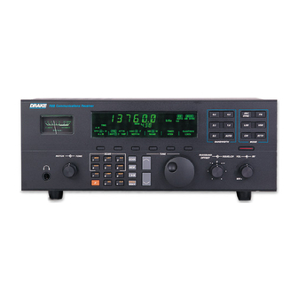
LAMP BEEP M/KHz A PASSBAND OFFSET control also aids in reducing or The R8B communications receiver is a microprocessor controlled, synthesized, all mode, world band receiver eliminating interfering signals by electronically shifting the receiver's IF frequencies without disturbing the operating with continuous coverage capability from 100 through 30,000 kHz. -
Page 8: Specifications / Accessories
Introduction - Specifications / Accessories Frequency Range 100-30,000 kHz - Intercept Point +20 dBm @ Modes AM, LSB, USB, CW, RTTY, FM (preamp off) 100 kHz spacing -20 dBm @ Sensitivity: SSB, CW (10dB 0.5 V nominal, 100-30,000 kHz 5 kHz spacing S+N/N) (preamp off) Less than 0.25 V, 100-30,000 kHz... -
Page 9: Safety Voltage Selection
Introduction - Safety / Voltage Selection SAFETY/VOLTAGE SELECTION WARNING!!! Please read before applying power The receiver is normally shipped with the input line voltage Antenna grounding is necessary if the unit is connected to selector switch set to 108-132 VAC for operation in the U.S. an outdoor antenna. -
Page 10: Installation
MOBILE INSTALLATION box. Locate the registration card, fill out, and immedi- ately return to the R. L. Drake Company to insure registra- For use in a mobile environment, the receiver includes a tion and validation of warranty. -
Page 11: Installation Diagram
Installation, continued FOR USE WITH DIPOLE LONGWIRE ATTENTION: LOCATE ANY OPTIONAL VHF LOW IMPEDANCE HIGH IMPEDANCE RECEIVER ANTENNAS SOME CONVERTER DISTANCE AWAY FROM TRANSMITTER ANTENNAS TO AVOID POSSIBLE DAMAGE TO THE RECEIVER 50 OHM COAXIAL CABLE 50 OHM - OR - DC POWER PLUG TO PL-259 COAXIAL... -
Page 12: Front Panel Description
Front Panel Description R8B Communications Receiver MODE SYNC AUTO AM SYNC 6.0 4.0 SCAN LSB USB 40 60 2.3 1.8 CW FM SEEK RTTY LIST TIME TUNE S UNITS DECIBLES CARR 12 ON OFF SIGNAL VFO A = B ATTN... - Page 13 Front Panel Description, continued The step size may be programmed per mode. The re- (VFO to Memory) - Pressing this button in VFO mode ceiver, as shipped from the factory, has step sizes pro- transfers the current status of the receiver, for example, grammed as shown in Table 1 below: frequency, mode, bandwidth, etc., into memory.
-
Page 14: Front Panel Display
Front Panel Display MODE AUTO AM SYNC 6.0 4.0 LSB USB SCAN 2.3 1.8 CW FM SEEK RTTY LIST TIME TUNE CARR 12 ON OFF ATTN AGC S NB N W TIMER CLK/FREQ VFO A = B A = B ANT 1 2 VHF NOTCH NAME... - Page 15 Front Panel Display, continued 10) AGC S/F - A box appears around the selected AGC setting. With no box illuminated, the AGC is Off. As the receiver is factory supplied, two choices are possible: S or F. Select either the Slow or Fast AGC setting for most all modes of operation.
-
Page 16: Rear Panel Description
Rear Panel Description WARNING CONV ANT 1 40 WATTS 50/60 Hz DISCONNECT FROM A N T 2 SUPPLY BEFORE CHANGING RANGES TYPE T EXT 11 - 16 VDC IN 108- 132V TIMER LINE AUDIO SPEAKER MUTE 100VAC 400 mA 120VAC 400 mA BOTH 200VAC 200 mA 240VAC 200 mA... -
Page 17: Mute Operation Of The Receiver
The mute line does not disconnect the antenna. Older is often desirable to be able to externally mute the Drake equipment required the mute line to be grounded receiver during transmission. The receiver provides this for receive. This receiver requires ground to mute. -
Page 18: Getting Started
Getting Started R8B Communications Receiver MODE SYNC AUTO AM SYNC 6.0 4.0 SCAN LSB USB 40 60 2.3 1.8 CW FM SEEK RTTY LIST TIME TUNE S UNITS DECIBLES CARR 12 ON OFF SIGNAL VFO A = B ATTN AGC S... -
Page 19: Dual Vfo's
Getting Started, continued The three choices are as follows: For example, suppose you want WWV at 10 MHz in VFO B A) 1 kHz display readout (tuning in 1 kHz steps). while using VFO A to tune other frequencies. Used for fairly rapid frequency search. Press: VFO to select B B) 100 Hz display readout (tuning in 100 Hz steps). -
Page 20: Front Panel Lock
Getting Started, continued FRONT PANEL LOCK (UNLOCK) detector should be engaged. Make sure the main tuning is set to within 1 kHz of the station’s transmitting frequency. First be sure the receiver is in the VFO mode, ( MEM or SCAN not displayed). -
Page 21: Rf Function (Attenuator/Preamplifier)
Getting Started, continued TUNE SCAN PASSBAND NOTCH TONE SQUELCH OFFSET LIST A - B SCAN SEEK TIME CARR LAMP BEEP M/KHz NOTCH TONE SQUELCH PASSBAND OFFSET RF GAIN VOLUME CENTERED CENTERED COUNTER-CLOCKWISE CENTERED CLOCKWISE COUNTER-CLOCKWISE FIGURE 10 RF FUNCTION (ATTENUATOR/PREAMP) CW OPERATION Occasionally, a received signal may be very strong such For general tuning in CW mode, the 1.8 kHz bandwidth is... -
Page 22: Fm Operation
Getting Started, continued R8B Communications Receiver MODE SYNC AUTO AM SYNC 6.0 4.0 SCAN LSB USB 40 60 2.3 1.8 CW FM SEEK RTTY LIST TIME TUNE S UNITS DECIBLES CARR 12 ON OFF SIGNAL VFO A = B ATTN... -
Page 23: Memory Functions
Memory Functions R8B Communications Receiver MODE SYNC AUTO AM SYNC 6.0 4.0 SCAN LSB USB 40 60 2.3 1.8 CW FM SEEK RTTY LIST TIME TUNE S UNITS DECIBLES CARR 12 ON OFF SIGNAL VFO A = B ATTN AGC S... -
Page 24: Memory Channel Programming
Memory Functions, continued MEMORY CHANNEL PROGRAMMING To save any altered settings, press the button, and First be sure the receiver is in the VFO mode (MEM, MEM within three seconds, enter the three digit memory num- not displayed). TUNE or SCAN ber. -
Page 25: Scan Functions
Scan Functions SCAN FUNCTIONS The receiver provides nine distinct scan functions which are programmed with keys 1-6 on the numeric keypad and indicated in the scan status area of the display. Keys 1-3 are considered modes. Scans all unlocked memory locations. s Receiver Scans all unlocked memory locations within LIST... -
Page 26: Scan Memory List Block
Scan Functions, continued SCAN MEMORY LIST BLOCK upper left-hand numeric digits of the display. The two- The memory channels 000 to 999 are partitioned into 100 digit Index number (00-99) serves to catalog multiple List LISTS (blocks), with each block having ten memory chan- nels (total of 1000 channels). -
Page 27: Scan A - B
Scan Functions, continued SCAN A - B To program a 9 kHz step rate for overseas broadcast band An A-B scan allows continuous tuning of frequencies reception- between two programmed limits. Table 4 charts the tuning step size and display resolution for the various Press POWER to turn receiver off modes. -
Page 28: Clock And Timer Functions
Clock and Timer Functions R8B Communications Receiver MODE SYNC AUTO AM SYNC 6.0 4.0 SCAN LSB USB 40 60 2.3 1.8 CW FM SEEK RTTY LIST TIME TUNE S UNITS DECIBLES CARR 12 ON OFF SIGNAL VFO A = B... -
Page 29: Enabling/Disabling Timer Operation
Clock and Timer Functions, continued Press the desired numeric buttons to enter a new ON Timer 1 Enabled; Timer 2 Disabled time. Enter the time in ‘HH:MM’ and in 24 hour format. Press the button followed by the button to MODE remove the ‘On Time’... - Page 30 Clock and Timer Functions, continued It is important to note that the timer is enabled only when 3) Example for Setting Overlapping Events: the timer is deliberately changed from a to 1, or to 2. With frequency displayed, suppose it is desired to Even if the 1 or 2 is already displayed, the timer is not record a one hour program on one frequency with a enabled unless the...
-
Page 31: Timer Connector Interface
Clock and Timer Functions, continued TIMER CONNECTOR INTERFACE WARNING!!! A standard 5 pin DIN connector located on the rear panel DO NOT USE TIMER CONNECTIONS TO SWITCH STANDARD provides the connections for unattended, programmed 120 VAC LINE OPERATED EQUIPMENT DIRECTLY. MAXIMUM Timer control of cassette recorders, RTTY or FAX demodu- RATINGS OF TIMER CONNECTIONS ARE 30 VDC AT 1 AM- lators, etc. -
Page 32: Special Use Features And Functions
Special Use Features and Functions This receiver has several special features that are referred 10 kHz/9 kHz SCAN to in the main body of this owner's manual but may require If a selected scan range includes the 540-1800 kHz broad- additional explanation. -
Page 33: Rs232C Interface
RS-232C Interface The receiver rear panel provides a common DB-9 con- NOTE: nector which conforms to the RS-232C serial data com- The following additional items apply when using the munications standard with the receiver configured as RS-232C Interface capability of the receiver: DCE. - Page 34 [nnn] Store (Program) Channel (nnn=000 through 999) CR AND LF Enter key 3. Information Retrieval Identify Receiver (5) R8B.n CR LF Output Control (8) (On, Off) OO, OF CR AND LF Report (9) RA, RC, RF, RM, RN, RSS, RSL...
- Page 35 Invalid commands result in a ‘Not recognized’ response. (9) Report types may be entered in any combination for customized reports. Transfers to and from a PC to an R8B can be made using a terminal program capable of Raw ASCII data transfer, such as PROCOMM PLUS 2.0 for DOS.
- Page 36 This reduces the data for a blank channel from 8 meaningless nn = two digits 0-9 c = any ASCII character value, in the R8B character set bytes to only 1. Data sent in a block store must be terminated with a hex value of 7D.
-
Page 37: Glossary Of Terms
Glossary of Terms 1) AC Input - Alternating Current power source available parallel glass plates with conductive coatings sandwich- at wall outlet sockets. ing a liquid-crystal compound between them. The com- pound becomes opaque and reflective when subjected 2) AM - Amplitude Modulated signals in which the infor- to an electric field. -
Page 38: Suggested References
Suggested References SUGGESTED REFERENCES 4) The ARRL Handbook 1) Passport to World Band Radio Published by: Published by: The American Radio Relay League International Broadcasting Services, Ltd. P. O. Box 300 Newington, CT USA 06111 Copyright © 1989 by The American Radio Relay League Penn's Park, Pennsylvania 18943 Library of Congress Catalog Card Number: 41-3345 2) World Radio TV Handbook... -
Page 39: Quick Reference Guide
Quick Reference Guide Press VFO function button until desired VFO is enclosed in box. Select VFO (page 13) Select VFO function button. Use numeric keypad, , or tuning Adjust Frequency (page13) wheel. Preamp or Attenuator (page 15) Press PRE ATTN function button until a box encloses ATTN Select AGC (page 9, 16) Press AGC function button until desired AGC action is enclosed in box. - Page 40 Quick Reference Guide Press press Press until dial lighting is at desired level. Dim Lamp (7,26) LAMP Press press to enable or disable beep. Disable Beep (7) BEEP MEMORY FUNCTIONS Program Memory Channel (page 18) Select VFO & mode, adjust frequency & bandwidth. Press (MEM will flash), use keypad to enter 3 digit memory...
-
Page 41: Troubleshooting
Troubleshooting TROUBLESHOOTING Symptom Probable Cause Corrective Action No front panel display or lights A) Power connection A) Check power supply cables when power is depressed B) Blown supply fuse B) Check fuse C) Contact service Scrambled front panel display A) Microprocessor malfunction A) Unplug from power source and re- when power is depressed connect to reset microprocessor... -
Page 42: Service
Typically, equipment is repaired in five to ten working Inside the carton, enclose a note with your name, days after it arrives at R. L. DRAKE if we have all the facts. address, daytime phone number, and a description of If we must call you, it may take longer. -
Page 43: Warranty
During the warranty period the R.L.DRAKE COMPANY or an authorized Drake service facility will provide, free of charge, both parts and labor necessary to correct defects in material and workmanship. At its option, R. L. DRAKE COMPANY may replace a defective unit. - Page 44 ® R. L. Drake Company 230 Industrial Drive Franklin, Ohio 45005 U.S.A. Customer Service and Parts Telephone: +1 (513) 746-6990 Telefax: +1 (513) 743-4576 World Wide Web Site: http://www.rldrake.com...
Need help?
Do you have a question about the R8B and is the answer not in the manual?
Questions and answers