Kenwood TK-860G Service Manual
Uhf fm transceiver
Hide thumbs
Also See for TK-860G:
- Service manual (67 pages) ,
- Service manual supplement (36 pages) ,
- Instruction manual (77 pages)
Table of Contents
Advertisement
Advertisement
Table of Contents

Related Manuals for Kenwood TK-860G


Summary of Contents for Kenwood TK-860G
- Page 1 UHF FM TRANSCEIVER TK-860G/ /862G/ SERVICE MANUAL 5 TONE © 2003-2 PRINTED IN JAPAN B51-8563-10 ( N ) *** REVISED TK-860G/(N) Panel assy Cabinet (Upper) (A62-0642-03) (A01-2165-13) Key top (K29-5343-02) TK-862G/(N) Panel assy (A62-0731-03) Key top (K29-5344-02)
-
Page 2: Table Of Contents
PERSONNEL SAFETY PC BOARD VIEWS The following precautions are recommended for person- DISPLAY UNIT (X54-3270-10) : TK-860G ..54 nel safety : • DO NOT transmit if someone is within two feet (0.6 DISPLAY UNIT (X54-3280-10) : TK-862G ..55 meter) of the antenna. -
Page 3: General
Your KENWOOD dealer can help you select an antenna sys- tem that will best serve your particular needs. 2-2. Testing 4-2. -
Page 4: System Set-Up
Are you using the external speaker? External speaker (Option) See page 21. See page 22. KCT-19 KCT-18 Are you using ignition sense cable? Accessory connector cable Ignition sense cable (Option) (Option) : You can install either KCT-19 or KCT-20 to the Delivery TK-860G/862G transceiver... -
Page 5: Operating Features
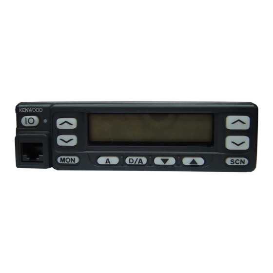
Insert the microphone plug into this connector. Appears when the AUX port is MON, A, D/A, , and SCN keys (TK-860G) activated. Flashes orange when the MON, , , and A keys (TK-862G) These are PF (Programmable Function) keys. Press each Talk-Around feature is active. -
Page 6: Operating Features
TK-860/G /862G/ OPERATING FEATURES 1-5. Rear panel 2. Operation Features The TK-860G/862G is a UHF FM radio designed to oper- ate in conventional format. The programmable features are summarized. Power input connector 3. Transceiver Controls and Indicators 3-1. Front Panel Controls... - Page 7 The transceiver mutes the speaker while receiv- ing. Following the above sequence, the transceiver contin- ues to transmit and receive. • Emergency mode system chart (TK-860G) Foot switch 1 push (Hold it down for about one second.) Emergency mode...
- Page 8 TK-860/G /862G/ OPERATING FEATURES • Group up/down (TK-860G only) • Talk around When the key is pressed each time, the group number to Press this key, the transceiver uses the receive fre- be selected is incremented/decremented and repeats if held quency and the tone for transmission.
- Page 9 DTMF ID (EOT) is sent on end of transmission. rent channel to answer to the call however revert channel is set to priority channel. Radio password (TK-860G only) After resume time, scan re-starts and transmission chan- When the password is set in the transceiver, user can not nel is return to priority channel.
-
Page 10: Audible User Feedback Tones
TK-860/G /862G/ OPERATING FEATURES “TOT” re-key time Dead Beat Disable The transceiver has “TOT” re-key timer. This timer is the If the D.B.D. code matches, a predetermined action will time you can not transmit after “TOT” exceeded. After occur. Whether option signalling is activated or not, when “TOT”... -
Page 11: Realignment
]+Power ON (Two seconds) Clone mode [ ]+Power ON (Two seconds) Self programming mode [A]+Power ON (Two seconds) 3. For the Panel Test Mode (TK-860G only) Setting method refer to ADJUSTMENT. 3-1. For the Panel Tunning Mode Setting method refer to ADJUSTMENT. - Page 12 3. Set the communications speed (normally, 57600 bps) • Change the TK-860G/862G to PC mode, then attach the and communications port in the Setup item. interface cable.
- Page 13 The operation is as follows (the transmit radio is the master and the receive radio is the slave). 1. Turn the master TK-860G power ON with the [ ] key held down. If the password is set to the TK-860G, the TK-860G displays “CLN LOCK”.
- Page 14 TK-860G/ /862G/ REALIGNMENT 8-1. Enter to the Self Programming Mode 9. Channel Setting Mode Remove D507 (Figure 3) from the TX-RX unit. Hold down Each channel can be setup in its action mode by using the [A] key and turn the power switch on. When enter the the panel keys.
- Page 15 TK-860G/ /862G/ REALIGNMENT No. Function Choices Display Remarks No. Function Choices Display Remarks Blank T. - - - - - - - [ ] : Frequency on/ 12 Priority P.CH_NO__ Not used when (Scan) 100.0000~ T.450.0000 blank switching channel Yes P.CH_YES_ priority is not fixed...
- Page 16 TK-860G/ /862G/ REALIGNMENT 9-1. Flow Chart No. Function Choices Display Remarks 18 Decode 1 ID OFF DEC1_OFF Turn the [CH ] key. Self programming (Only when Decode A-F DEC1___A mode [MON] 5-tone is [MON] Channel setting Channel selection Group selection...
- Page 17 OFF, 1~10/ TOTP_OFF Cannot be set when pre-alert 1s step TOT is off time Default : Off 11. Memory Reset Mode (TK-860G only) OFF, 1~60/ TOTK_OFF Cannot be set when rekey 1s step TOT is off You can clear all settings you made in self programming mode, or you can return to the original display.
-
Page 18: Installation
TK-860G/ /862G/ INSTALLATION 1-2. KCT-19 Accessory Port Function 1. Accessory Connection Cable Name Function Note (KCT-19 : Option) (A) (B,C,D,E) The KCT-19 is an accessory connection cable for con- Data channel control/ necting external equipment. The connector has 15 pins and External hook input the necessary signal lines are selected for use. - Page 19 TK-860G/ /862G/ INSTALLATION 2. Accessory Terminal (TX-RX Unit) 3. Ignition Sense Cable (KCT-18 : Option) 2-1. External Connector Accessory Terminal Method The KCT-18 is an optional cable for enabling the ignition function. The ignition function lets you turn the power to the...
- Page 20 TK-860G/ /862G/ INSTALLATION 4-2. Modifying the Transceiver Operation when KCT-18 R134 R135 • Horn alert is connected The signal from pin 4 of IC9 on the TX-RX unit turns Q5 Enable ← KCT-18 cannot Enable and Q1 on and off and drives KAP-1 HA relay K2 to drive the...
-
Page 21: Emergency Mode
TK-860G/ /862G/ INSTALLATION 4-3. Others If the PA and HR2 are not necessary and the speaker out- put is output to an external unit through the KCT-19, connect the KCT-19 C connector to CN8 on the TX-RX unit. KAP-1 (SWITCH UNIT : X41-3380-20) - Page 22 TK-860G/ /862G/ INSTALLATION 6. Fitting the Control Panel Upside Down The TK-860G/862G control panel can be fitted upside TX-RX unit B/2 Foil side down, so the transceiver can be mounted with its internal speaker (in the upper half of the case) facing down in your car.
-
Page 23: External Speaker
TK-860G/ /862G/ INSTALLATION 7-2. KES-4 : Option 6. Rotate the control panel 180 degrees and mount it on the transceiver. Refit the two halves of the case to complete The KES-4 is an external speaker used with the acces- installation. (Fig. 13) sory connection cable. -
Page 24: Circuit Description
TK-860G/ /862G/ CIRCUIT DESCRIPTION IF Amplifier Frequency Configuration The first IF signal is amplified by Q13, and the enters IC5 The receiver utilizes double conversion. The first IF is (FM processing IC). The signal is heterodyned again with a 49.95MHz and the second IF is 450kHz. The first local oscil- second local oscillator signal within IC5 to create a 450kHz lator signal is supplied from the PLL circuit. - Page 25 PROCE. Fig. 5) CONV. DTMF The TK-860G/862G has VCO in a Sub-unit (A1) housed in a solid shielded case and connected to the TX-RX unit FIg. 3 AF signal system through CN101. The operating frequency is generated by Q103 in trans- mit mode and Q101 in receive mode.
- Page 26 TK-860G/ /862G/ CIRCUIT DESCRIPTION Unlock Circuit Transmitter System During reception, the 8RC signal goes high, the 8TC sig- Outline nal goes low, and Q16 turns on. Q18 turns on and a voltage The transmitter circuit produces and amplifies the de- is applied to the collector (8R).
- Page 27 Fig. 11 Display circuit modulation and transmission power. Key Matrix Circuit LCD ASSY The TK-860G/862G front panel has function keys. Each TX-RX UNIT of them is connected to a cross point of a matrix of the KIN0 IC510 to KOUT2 ports of the microprocessor. The KOUT0 to...
- Page 28 TK-860G/ /862G/ CIRCUIT DESCRIPTION Decode PA Switch • QT/DQT/DTMF If the optional KAP-1 is used (see the separate section for details), the PA (Public Address) function becomes avail- The signal (DEO) detected by the TX-RX unit passes able. In this case, the signal flow changes as follows;...
-
Page 29: Semiconductor Data
TK-860G/ /862G/ SEMICONDUCTOR DATA Microprocessor : 30622M4102GP (TX-RX Unit IC502) Terminal function Pin No. Name Function Pin No. Name Function EMGT External MIC control. Mobile MIC : H HOLD Not used. DTMF DTMF/2TONE/BEEP/5TONE output. 40,41 – 2TONE and 5TONE decode pulse input. - Page 30 TK-860G/ /862G/ SEMICONDUCTOR DATA Shift Register : BU4094BCFV LCD Driver : LC75833W Terminal function (TX-RX unit IC510) (Display Unit IC801 : TK-862G only) Pin No. Port Name Function Block diagram Not used. MUTE MIC mute (M models only). Mute : H MIC/LCD backlight control.
-
Page 31: Description Of Components
D505 Reverse current KOUT 1 TX-RX Unit (X57-596X-XX) prevention 2-71 : TK-862G 2-72 : TK-862G(N) D506 Voltage discharger When powering down 2-73 : TK-860G 2-74 : TK-860G(N) D507 Reverse current KOUT 2 Ref. No. Use/Function Operation/Condition prevention Surge absorption D508... - Page 32 TK-860G/ /862G/ DESCRIPTION OF COMPONENTS Ref. No. Use/Function Operation/Condition Ref. No. Use/Function Operation/Condition RF amplifier Predrive IC10 5V AVR 5C (TX/RX) Inverter Active while power switch is low IC11 9V AVR IC12 8V AVR RF amplifier Drive DC switch 8T, active on TX...
-
Page 33: Parts List
TK-860G/ /862G/ PARTS LIST CAPACITORS CC 45 TH 1H 220 J • Capacitor value Color* CC45 010 = 1pF 0 = 22pF 100 = 10pF 1 = Type … ceramic, electrolytic, etc. 4 = Voltage rating Multiplier 101 = 100pF 2 = Shape …... -
Page 34: Parts List
Les articles non mentionnes dans le Parts No. ne sont pas fournis. Y : AAFES (Europe) X: Australia M: Other Areas Teile ohne Parts No. werden nicht geliefert. TK-860G/(N)/862G/(N), DISPLAY UNIT (X54-3270-10) : TK-860G/(N), DISPLAY UNIT (X54-3280-10) : TK-862G/(N), Desti- Desti- Ref. No. - Page 35 Description parts nation parts nation CC73GCH1H020B CHIP C 2.0PF TX-RX UNIT (X57-596X-XX) CK73GB1H471K CHIP C 470PF 2-71 : TK-862G 2-72 : TK-862G(N) 2-73 : TK-860G 2-74 : TK-860G(N) C92-0555-05 CHIP-TAN 0.047UF 35WV C94-96 CK73GB1H471K CHIP C 470PF D509-514 B30-2050-05 C92-0546-05...
- Page 36 TK-860G/ /862G/ PARTS LIST TX-RX UNIT (X57-596X-XX) Desti- Desti- Ref. No. Address Parts No. Description Ref. No. Address Parts No. Description parts nation parts nation C166 CE04EW1E471M ELECTRO 470UF 25WV C270 CK73GB1H471K CHIP C 470PF C167 CK73GB1H471K CHIP C 470PF...
- Page 37 TK-860G/ /862G/ PARTS LIST TX-RX UNIT (X57-596X-XX) Desti- Desti- Ref. No. Address Parts No. Description Ref. No. Address Parts No. Description parts nation parts nation C574 CC73GCH1H470J CHIP C 47PF L34-4530-05 COIL C575 CK73GB1H102K CHIP C 1000PF L40-8275-77 SMALL FIXED INDUCTOR (82NH)
- Page 38 TK-860G/ /862G/ PARTS LIST TX-RX UNIT (X57-596X-XX) Desti- Desti- Ref. No. Address Parts No. Description Ref. No. Address Parts No. Description parts nation parts nation RK73GB1J104J CHIP R 100K 1/16W R105 RK73GB1J101J CHIP R 1/16W R28,29 R92-1252-05 CHIP R 0 OHM...
- Page 39 TK-860G/ /862G/ PARTS LIST TX-RX UNIT (X57-596X-XX) Desti- Desti- Ref. No. Address Parts No. Description Ref. No. Address Parts No. Description parts nation parts nation R176 RK73GB1J103J CHIP R 1/16W R547 RK73GB1J103J CHIP R 1/16W R177 R92-1261-05 CHIP R 1/2W...
- Page 40 TK-860G/ /862G/ PARTS LIST TX-RX UNIT (X57-596X-XX) Desti- Desti- Ref. No. Address Parts No. Description Ref. No. Address Parts No. Description parts nation parts nation R616 RK73GB1J474J CHIP R 470K 1/16W IC15 TA75S01F IC (OP AMP) R617 RK73GB1J472J CHIP R 4.7K...
- Page 41 TK-860G/ /862G/ PARTS LIST PLL/VCO (X58-4670-15) Desti- Desti- Ref. No. Address Parts No. Description Ref. No. Address Parts No. Description parts nation parts nation PLL/VCO (X58-4670-15) C102 CK73GB1H471K CHIP C 470PF C104,105 CC73GCH1H070D CHIP C 7.0PF C107 CC73GCH1H040B CHIP C 4.0PF...
-
Page 42: Exploded View
TK-860G/ /862G/ EXPLODED VIEW (TK-860G) Parts with the exploded numbers larger than 700 are not supplied. - Page 43 TK-860G/ /862G/ EXPLODED VIEW (TK-862G) Parts with the exploded numbers larger than 700 are not supplied.
-
Page 44: Packing
TK-860G/ /862G/ PACKING 13 DC cord 33 Protection bag (E30-3339-05) 5 Cap (H25-0720-04) (B09-0235-05) 19 Fuse (10A) (F51-0016-05) x 2 38 Bracket (J29-0627-23) 32 Inner packing case (H12-1391-03) 36 Holder (J19-1584-05) 42 Screw set (N99-0395-05) 31 Polystyrene foamed fixture (R) -
Page 45: Adjustment
TK-860G/ /862G/ ADJUSTMENT • Signalling Test Mode (TK-860G Only) Signalling No. Test Mode Operating Features None None This transceiver has a test mode. To enter test mode, press [SCN] key and turn power on. Hold [SCN] key un- None 100Hz square til test channel No. - Page 46 TK-860G/ /862G/ ADJUSTMENT Tuning Mode Display Function name FREQ_ _XX Frequency adj. HPOW_XXX H.POW_XXX H.P.OW_XXX H.P.O.W_XXX H.P.O.W._XXX H.P.O.W._.XXX RF high power Hi power (L) Hi power (L') Hi power (C) Hi power (H') Hi power (H) [D/A] [D/A] [D/A] [D/A]...
- Page 47 TK-860G/ /862G/ ADJUSTMENT Test Equipment Required for Alignment Test Equipment Major Specifications 1. Standard Signal Generator Frequency Range 400 to 520MHz (SSG) Modulation Frequency modulation and external modulation Output –127dBm/0.1µV to greater than –7dBm/100mV 2. Power Meter Input Impedance 50Ω...
- Page 48 TK-860G/ /862G/ ADJUSTMENT Adjustment Point Adjustment Location Switch (TK-860G) Volume Channel Power up/down Display up/down TX-RX UNIT (A/2) MIC jack Programmable function keys TC106 Note PLL/VCO RSSI • Flash memory TC109 The firmware program (User mode, Test mode, Tuning mode, etc.) and the data programmed by the FPU (KPG-67D) for the flash memory, is stored in memory.
- Page 49 1. To adjust TK-862G, use KPG-67D FPU, otherwise you cannot tune this transceiver from the front panel. 2. TK-860G NE and TK-862G NE are “Narrow” band models. TK-860G E and TK-862G E are “Wide (Wide 5k) & Semi wide (Wide 4k)”...
- Page 50 TK-860G/ /862G/ ADJUSTMENT Measurement Adjustment Item Condition Specifications/Remarks Test- Unit Terminal Unit Parts Method equipment 3. Squelch 3 1) Set test mode Rear Front CH / Adjust to the • Wide/ Select “SQL3” in tuning mode. panel panel squelch threshold Narrow “S.QL3”...
- Page 51 TK-860G/ /862G/ ADJUSTMENT Measurement Adjustment Item Condition Specifications/Remarks Test- Unit Terminal Unit Parts Method equipment 6. QT check 1) Set test mode Rear CH : CH1 - Sig4 panel SSG MOD AF VTVM INT : 3kHz (Wide), 1.5kHz (Narrow) Distortion (EXT.SP)
- Page 52 TK-860G/ /862G/ ADJUSTMENT Measurement Adjustment Item Condition Specifications/Remarks Test- Unit Terminal Unit Parts Method equipment ± 0.5W 3) “L.P.O.W” Power meter Rear Front CH / 6.0W PTT : ON panel panel Adjust [ *** ] 4) “L.P.O.W.” PTT : ON Adjust [ *** ] 5) “L.P.O.W._.”...
- Page 53 TK-860G/ /862G/ ADJUSTMENT Measurement Adjustment Item Condition Specifications/Remarks Test- Unit Terminal Unit Parts Method equipment ± 2.4kHz~± 3.4kHz (Wide) 8. MIC 1) Set test mode Power meter Rear Check ± 1.2kHz~± 1.7kHz (Narrow) seisitivity CH : CH1 - Sig1 Deviation...
-
Page 54: Pc Board Views
TK-860G/ /862G/ PC BOARD VIEWS DISPLAY UNIT (X54-3270-10) : TK-860G DISPLAY UNIT (X54-3270-10) : TK-860G Component side view Foil side view C806 C807 C807 C806 R808 R808 R809 R809 CN801 CN801 C801 C801 R801 R801 C802 C802 C803 C805 C805... -
Page 55: Display Unit (X54-3280-10) : Tk-862G
TK-860/G /862G/ PC BOARD VIEWS DISPLAY UNIT (X54-3280-10) : TK-862G DISPLAY UNIT (X54-3280-10) : TK-862G PLL/VCO (X58-4670-15) Component side view Component side view Foil side view J72-0676-02 C115 C119 L109 CN101 L103 C104 L112 (ST) 6 C122 R805 R803 R813 R813 R803 R805... - Page 56 TK-860G/ /862G/ TX-RX UNIT (X57-596X-XX) (A/2) PC BOARD VIEW Component side view 2-71 : TK-862G 2-72 : TK-862G(N) 2-73 : TK-860G 2-74 : TK-860G(N) Ref. No. Address Ref. No. Address Ref. No. Address Ref. No. Address IC13 IC400 Component side...
- Page 57 Ref. No. Address Ref. No. Address Ref. No. Address Ref. No. Address Ref. No. Address Ref. No. Address 2-71 : TK-862G 2-72 : TK-862G(N) 2-73 : TK-860G 2-74 : TK-860G(N) Q10 13G D11 12G D23 12R IC10 Q13 13K D14 10H...
-
Page 58: Tx-Rx Unit (X57-596X-Xx) (A/2)
Ref. No. Address Ref. No. Address Component side view + Foil side IC13 Q10 13M D11 12M D40 11M 2-71 : TK-862G 2-72 : TK-862G(N) 2-73 : TK-860G 2-74 : TK-860G(N) IC14 Q11 11G Q34 10C IC15 Q12 11G D15 10R... -
Page 59: Tx-Rx Unit (X57-596X-Xx) (B/2)
TK-860G/ /862G/ PC BOARD VIEWS TX-RX UNIT (X57-596X-XX) (B/2) Component side view 2-71 : TK-862G 2-72 : TK-862G(N) 2-73 : TK-860G 2-74 : TK-860G(N) D512 J72-0760-12 B/2 D511 C640 + R566 C543 C632 L501 R567 R560 C501 C542 IC510 R561... - Page 60 TK-860G/ /862G/ PC BOARD VIEW TX-RX UNIT (X57-596X-XX) (B/2) Component side view + Foil side 2-71 : TK-862G 2-72 : TK-862G(N) 2-73 : TK-860G 2-74 : TK-860G(N) J72-0760-12 B/2 D512 R550 D511 R548 R501 C640 + R553 R612 C534 R566...
- Page 61 TK-860G/ SCHEMATIC DIAGRAM Note : Components marked with a dot (·) are parts of patterun 1.
-
Page 62: Schematic Diagram
TK-862G/ SCHEMATIC DIAGRAM Note : Components marked with a dot (·) are parts of patterun 1. -
Page 63: Block Diagram
TK-860G/ /862G/ TK-860G/ /862G/ TK-860G/ /862G/ BLOCK DIAGRAM... -
Page 64: Level Diagram
TK-860G/ /862G/ TK-860G/ /862G/ LEVEL DIAGRAM Receiver Section Center Frequency 49.95MHz 450kHz Audio Frequency W/N 540mVrms W/N 520mVrms W/N 630mVrms SW 432mVrms SW 416mVrms SW 504mVrms To make measurements in the RF section, connect the RF level meter. In the RF section, use a 0.01µF coupling capacitor. -
Page 65: Terminal Function
TK-860G/ /862G/ TERMINAL FUNCTION CN1 (TX-RX Unit) CN3 (TX-RX Unit) Pin No. Name Function Pin No. Name Function DC 8V output. Horn alert/call output. DC 5V output. Ground. AUX5 Switched B+, DC 13.2V output, Maximum 1A. AUX6 Non-connection CN4 (TX-RX Unit) AUX3 SQ : Squelch detect output. -
Page 66: Specifications
GENERAL Frequency Range ........ 440 to 470MHz Number of Channels ......TK-862G : Maximum 8 channels TK-860G : Maximum 128channels Number of Groups ......TK-860G : Maximum 128 groups Channel Spacing TK-860G/862G ........ Wide : 25kHz Semi wide : 20kHz TK-860G(N)/862G(N) ...... - Page 67 Leuvensesteenweg 248 J, 1800 Vilvoorde, Belgium KENWOOD ELECTRONICS FRANCE S.A. 13, Boulevard Ney, 75018 Paris, France KENWOOD ELECTRONICS U.K. LIMITED KENWOOD House, Dwight Road, Watford, Herts., WD18 9EB United Kingdom KENWOOD ELECTRONICS EUROPE B.V. Amsterdamseweg 37, 1422 AC Uithoorn, The Netherlands KENWOOD ELECTRONICS ITALIA S.p.A.
Need help?
Do you have a question about the TK-860G and is the answer not in the manual?
Questions and answers