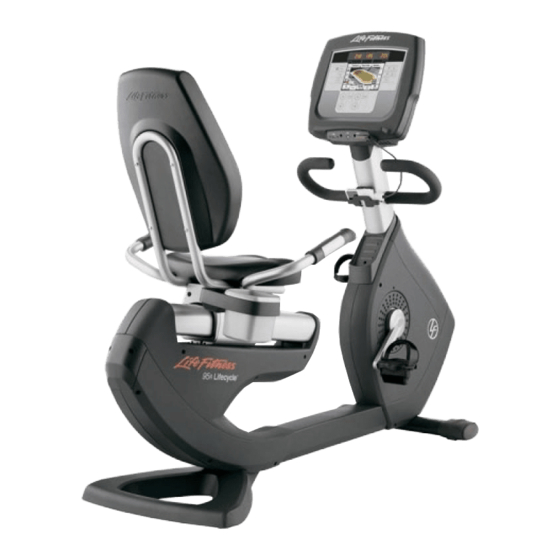
Life Fitness Lifecycle 95R Assembly Instructions Manual
Hide thumbs
Also See for Lifecycle 95R:
- Operation manual (44 pages) ,
- User manual (43 pages) ,
- Operation manual (42 pages)
Table of Contents
Advertisement
Available languages
Available languages
Advertisement
Table of Contents

Subscribe to Our Youtube Channel
Related Manuals for Life Fitness Lifecycle 95R


Summary of Contents for Life Fitness Lifecycle 95R
- Page 1 95R Recumbent Lifecycle Exercise Bike ® Assembly Instructions...
- Page 2 Congratulations... and welcome to the world of The following Parts List and the step-by-step assembly procedures have been assem- bled to make the set-up of the Recumbent Lifecycle ® Exercise Bike as quick and easy as possible. Please take special note of the following important points prior to choosing a location ®...
-
Page 3: Important Safety Instructions
DO verify the contents of the delivery carton against the accompanying Parts Listing prior to setting the cartons and shipping material aside. If any parts are missing, contact Life Fitness Customer Support Services at the number listed in the Operation Manual. Save the shipping cartons in case of return. -
Page 4: Parts Description
TOOLS REQUIRED FOR ASSEMBLY... Magnetic #2 Bit Phillips Screwdriver, 6mm Hex Key Allen Driver and Ratchet, Side Cutters, 17mm socket and Ratchet PARTS DESCRIPTION Monocolumn Assembly Qty: M10 X 90MM Screw Qty: 3 0017-00101-2035 Phillips Screw Qty: Display Console Qty: 1 0017-00101-1796 Rear Cover Qty:... - Page 5 IMPORTANT! DO NOT DISCARD THE SHIP KIT. ALL NECESSARY COMPONENTS NEEDED TO COMPLETE THE INSTALLATION ARE LOCATED IN THE SHIP KIT. IMPORTANT! NE JETEZ PAS LE KIT. IL CONTIENT TOUS LES ÉLÉMENTS NÉCESSAIRES POUR L'INSTALLATION. Position the unit base near its location for use. Remove the USER LEFT CRANK ARM HOLE PLUG (A) and set it aside.
- Page 6 Position the HANDLEBARS (7) as shown. Secure each HANDLEBAR to the SEAT FRAME (N) using two M8 x 20mm SCREWS (8) and two M8 WASHERS (9) each. NOTE: Be sure the the TABS of the HANDLEBARS are inserted into the slots on the underside of the SEAT FRAME as shown in the detail before securing.
- Page 7 For units with Engage Consoles Position the unit in its final position for use. Remove the protective liner from one of the provided FASTENER STRIPS. Attach the fastener strip to the bottom of the POWER BLOCK (16). Interlock the remaining FASTENER STRIP to the installed FASTENER STRIP.
-
Page 8: Physical Dimensions
Operation Manual. If your Recumbent Lifecycle ® Exercise Bike does not respond as described in the Operation Manual, contact the nearest Life Fitness service center as listed in the Operation Manual. Life Fitness Customer Support Services (800) 351-3737 or (847) 451-0036 Prior to your call, please be sure you have located and noted the MODEL NUMBER &... - Page 9 95R Lifecycle Liegeergometer ® Montageanleitung...
- Page 10 Herzlichen Glückwunsch... und willkommen bei Die folgende Teileliste und schrittweise Montageanleitung dienen dazu, den Aufbau dieses Lifecycle ® Liegeergometers so einfach wie möglich zu machen. Bitte lesen Sie die nachfolgenden Informationen sorgfältig, bevor Sie einen Standort für das Lifecycle ® Liegeergometer wählen und mit der Montage beginnen.
-
Page 11: Wichtige Sicherheitsvorkehrungen
Teile des Geräts mit Wasser in Berührung gekommen sind. Wenden Sie sich in diesem Fall unter der im Benutzerhandbuch angegebenen Nummer an den Life Fitness Kundendienst. Den Heimtrainer mit MINDESTENS 30 in. (76 cm) Abstand zu einem Fernsehgerät aufstellen. -
Page 12: Beschreibung Der Teile
BENÖTIGTES WERKZEUG FÜR DIE MONTAGE... Magnetischer Kreuzschlitzschraubendreher, 6 mm Inbusschlüssel und Ratsche, Seitenschneider, 17 mm Steckschlüssel und Ratsche BESCHREIBUNG DER TEILE Einzelsäule Anz: 1 M10 X 90 mm Schraube Anz: 3 0017-00101-2035 Kreuzschlitzschraube Anz: 1 Display-Konsole Anz: 1 0017-00101-1796 Hintere Abdeckung Anz: 1 M5 x 14 mm Kreuzschlitzschraube Anz: 4... - Page 13 WICHTIG! DAS VERSANDKIT NICHT ENTSORGEN. DIESES KIT ENTHÄLT ALLE FÜR DIE INSTALLATION BENÖTIGTEN KOMPONENTEN. Das Gerät in der Nähe des Verwendungsortes positionieren. Den VERSCHLUSSSTECKER FÜR DEN LINKEN TRETKURBELARM (A) ENTFERNEN und zur Seite legen. Die SCHRAUBE DES LINKEN TRETKURBELARMS (B) ENTFERNEN und den TRETKURBELARM (C) von der Einheit ziehen. Beide Teile aufbewahren.
- Page 14 Die HALTEGRIFFE (7) wie gezeigt positionieren. Jeden HALTEGRIFF mit je zwei M8 x 20mmSCHRAUBEN (8) und je zwei M8 UNTERLEGSCHEIBEN (9) am SITZRAHMEN (N) befestigen. HINWEIS: Sicherstellen, dass die ZUNGEN der HALTEGRIFFE wie gezeigt in die Schlitze unter dem SITZRAHMEN eingeschoben werden, bevor die Haltegriffe befestigt werden.
- Page 15 Für Einheiten mit Engage Konsole Das Gerät am dauerhaften Aufstellungsort positionieren. Den Schutzfilm von einem der HAFTSTREIFEN abziehen. Den Haftstreifen an der Unterseite des STROMBLOCKS (16) ANBRINGEN. Den verbleibenden HAFTSTREIFEN am befestigten HAFTSTREIFEN ANBRINGEN. Den verbleibenden Schutzfilm vom HAFTSTREIFEN abziehen und den STROMBLOCK wie gezeigt auf der Unterseite des MITTELRAHMENS anbringen.
-
Page 16: Checkliste Vor Inbetriebnahme
Die Modell- und Seriennummern des Lifecycle ® Liegeergometers sind auf einem Schild an der hinteren Stabilisatorstange zu finden. © 2009 Life Fitness, eine Firma der Brunswick Corporation. Alle Rechte vorbehalten. Life Fitness ist ein Warenzeichen der Brunswick Corporation. M051-00K66-D010 1.09... - Page 17 95R Lifecycle ligfietshometrainer ® Aanwijzingen voor montage...
- Page 18 Gefeliciteerd... en welkom in de wereld van De bijgevoegde onderdelenlijst en de stapsgewijze montageprocedure zijn samengesteld om de montage van de Lifecycle ® ligfiets-hometrainer zo snel en eenvoudig mogelijk te laten verlopen. Wilt u speciale aandacht aan de volgende belangrijke punten schenken voordat u de ®...
-
Page 19: Belangrijke Veiligheidsaanwijzingen
Gebruik de hometrainer NIET als hij gevallen of beschadigd is, of als er water overheen gekomen is. Neem in zulke gevallen contact op met de klantendienst van Life Fitness, waarvan u het nummer in de gebruikershandleiding kunt vinden. Plaats de hometrainer NIET op minder dan 76 cm (30 inch) van een televisietoestel. -
Page 20: Beschrijving Onderdelen
BENODIGD GEREEDSCHAP... Kruiskopschroevendraaier met magnetisch bit nr. 2; 6 mm inbusmoersleutel met ratel, gehoekte kniptang; 17 mm steeksleutel met ratel BESCHRIJVING ONDERDELEN Kolom Aantal: 1 M10 X 90MM schroef Aantal: 3 0017-00101-2035 Kruiskopschroef Aantal: 1 Bedieningspaneel Aantal: 1 0017-00101-1796 Achterkap Aantal: 1 M5 x 14mm kruiskopschroef Aantal: 4... - Page 21 BELANGRIJK! GOOI DE VERPAKKINGSSET NIET WEG. ALLE ONDERDELEN DIE NODIG ZIJN OM DE INSTALLATIE TE VOLTOOIEN BEVINDEN ZICH IN DE VERPAKKINGSSET. Zet de hometrainer in de buurt van waar u hem wilt gebruiken. Verwijder de LINKER KRUKARMPLUG (A) en leg deze opzij. Verwijder de LINKER KRUKARMSCHROEF (B) en schuif de KRUKARM (C) van de eenheid.
- Page 22 Plaats de HANDGREPEN (7) zoals afgebeeld. Bevestig elke HANDGREEP op het ZADELFRAME (N) met twee M8 x 20mm SCHROEVEN (8) en twee M8 RINGEN (9) elk. OPMERKING: Controleer of de LIPPEN van de HANDGREPEN in de gleuven op de onderkant van het ZADELFRAME zijn gestoken, zoals afgebeeld, voordat u ze vastzet.
- Page 23 Voor hometrainers met Engage-bedieningspaneel Zet de hometrainer op zijn uiteindelijke gebruikslocatie. Verwijder het beschermmateriaal van een van de meegeleverde BEVESTIGINGSSTRIPS. Maak de bevestigingsstrip vast op de onderkant van het VOEDINGSBLOK (16). Verbind de andere BEVESTIGINGSSTRIP met de reeds geïnstalleerde BEVESTIGINGSSTRIP. Verwijder het resterende beschermmateriaal van de BEVESTIGINGSSTRIP en bevestig het VOEDINGSBLOK op de onderkant van het MIDDELSTE FRAME, zoals afgebeeld.
- Page 24 Indien uw Lifecycle ® ligfietshometrainer niet reageert zoals beschreven in de gebruikershandleiding, neem dan contact op met het dichtstbijzijnde servicecentrum van Life Fitness, waarvan de lijst is opgenomen in de gebruikershandleiding. De klantendienst van Life Fitness Telefoon (800) 351-3737 of (847) 451-0036 Zorg voordat u belt dat u het MODELNUMMER en SERIENUMMER bij de hand hebt.
- Page 25 Cyclette reclinata Lifecycle ® Istruzioni per il montaggio...
- Page 26 Congratulazioni... e benvenuti nel mondo di Il seguente elenco di identificazione dei componenti e le procedure dettagliate di montaggio sono stati redatti per rendere più facile e veloce possibile l’installazione ® della cyclette reclinata Lifecycle Prima di scegliere l’ubicazione della cyclette reclinata Lifecycle ®...
-
Page 27: Importanti Istruzioni Di Sicurezza
NON utilizzare la cyclette se ha subito urti, se è danneggiata o se è stata immersa in acqua anche solo parzialmente. In tali situazioni contattare il centro assistenza clienti Life Fitness telefonando al numero indicato nel manuale di funzionamento del prodotto. -
Page 28: Descrizione Dei Componenti
ATTREZZI NECESSARI PER IL MONTAGGIO Cacciavite a stella magnetico n. 2, chiave a brugola esagonale da 6 mm e cricchetto, taglierine, chiave a bussola da 17 mm e cricchetto DESCRIZIONE DEI COMPONENTI Gruppo monocolonna Qtà: Vite M10 x 90 mm Qtà: 3 0017-00101-2035 Vite a croce... - Page 29 IMPORTANTE NON GETTARE IL KIT DI IMBALLAGGIO, POICHÉ CONTIENE TUTTI I COMPONENTI NECESSARI PER COMPLETARE L’INSTALLAZIONE. Collocare la base dell’unità nell’ubicazione desiderata. Rimuovere il TAPPO SUL FORO DELLA PEDIVELLA SINISTRA (A) e metterlo da parte. Rimuovere la VITE DELLA PEDIVELLA SINISTRA (B) e sfilare la PEDIVELLA (C) dall’unità.
- Page 30 Posizionare i MANUBRI (7) come mostrato. Fissare ciascun MANUBRIO al TELAIO DEL SEDILE (N) con due VITI M8 x 20 mm (8) e due RONDELLE M8 (9). NOTA: Prima di fissarli assicurarsi che le LINGUETTE dei MANUBRI siano inserite nelle fessure sul lato inferiore del TELAIO DEL SEDILE come mostrato nella figura di dettaglio.
- Page 31 Per unità dotate di console Engage Posizionare l’unità nell’ubicazione desiderata. Rimuovere il rivestimento protettivo da una delle STRISCETTE DI FISSAGGIO in dotazione. Attaccare la striscetta di fissaggio sulla parte inferiore del GRUPPO DI ALIMENTAZIONE (16). Fissare la seconda STRISCETTA DI FISSAGGIO alla STRISCETTA DI FISSAGGIO già installata.
-
Page 32: Dimensioni Fisiche
Se la cyclette reclinata Lifecycle ® non funziona nel modo descritto nel manuale di funzionamento, contattare il centro assistenza clienti Life Fitness più vicino tra quelli elencati nel manuale di funzionamento. Centri di assistenza clienti Life Fitness +1 (800) 351-3737 o +1 (847) 451-0036 Prima di contattare il centro di assistenza individuare e annotare il NUMERO DI MODELLO e il NUMERO DI SERIE. - Page 33 Vélo d’exercice semi-allongé Lifecycle ® Instructions de montage...
- Page 34 Félicitations... et bienvenue dans le monde de La liste des pièces suivante et les instructions d’installation détaillées sont fournies afin de rendre l’installation de ces vélos semi-allongés Lifecycle ® aussi facile et rapide que possible. Portez une attention toute particulière aux points suivants avant de choisir un emplacement et de commencer à...
-
Page 35: Consignes De Sécurité Importantes
N’utilisez PAS le vélo d’exercice s’il est tombé, s’il a été endommagé ou s’il a été partiellement plongé dans l’eau. Contactez le service après-vente de Life Fitness au numéro fourni dans le manuel d’utilisation. NE placez PAS le vélo à moins de 30 pouces (76 cm) d’un poste de télévision. -
Page 36: Description Des Pièces
OUTILS NÉCESSAIRES POUR LE MONTAGE... Tournevis cruciforme magnétique n° 2, clé hexagonale à mèche de 6 mm et clé à rochet Allen, pince à tranchant latéral, douille et clé à rochet de 17 mm DESCRIPTION DES PIÈCES Colonne centrale Qté : 1 Vis M10 X 90 mm Qté... - Page 37 IMPORTANT ! NE JETEZ PAS LE KIT D’EXPÉDITION FOURNI AVEC LA MACHINE. TOUS LES ÉLÉMENTS NÉCESSAIRES À CETTE INSTALLATION SONT PLACÉS À L’INTÉRIEUR DU KIT. Positionnez la base de l’appareil à l’endroit où il sera utilisé. Retirez le BOUCHON DE L’ORIFICE DE MANIVELLE GAUCHE (A) et mettez-le de côté.
- Page 38 Positionnez les GUIDONS (7) comme illustré. Fixez chaque GUIDON au CADRE DU SIÈGE (H) à l’aide de deux VIS M8 x 20 mm (8) et de deux RONDELLES M8 (9) chacun. REMARQUE : Vérifiez que les LANGUETTES des GUIDONS sont insérées correctement dans les fentes figurant sous le CADRE DU SIÈGE, comme indiqué...
- Page 39 Pour les appareils dotés de consoles Engage Placez l’appareil là où il doit être utilisé. Retirez la pellicule de protection de l’une des BANDES DE FIXATION fournies. Attachez la bande de fixation au bas du BLOC D’ALIMENTATION (16). Sécurisez la BANDE DE FIXATION restante à la BANDE INSTALLÉE.
-
Page 40: Dimensions Hors Tout
® ne réagit pas conformément aux descriptions fournies dans ce manuel, contactez le service après-vente Life Fitness le plus proche de chez vous, indiqué dans cet ouvrage. Service d’assistance à la clientèle de Life Fitness (800) 351-3737 ou (847) 451-0036 Avant d’appeler, veuillez noter les NUMÉROS DE MODÈLE ET DE SÉRIE. - Page 41 Bicicleta reclinada para ejercicios Lifecycle 95R ® Instrucciones de montaje...
- Page 42 Felicitaciones... y bienvenido al mundo de La siguiente lista de piezas y los procedimientos de instalación paso a paso se han organizado para facilitar y agilizar el montaje de las bicicletas reclinadas para ® ejercicios Lifecycle Preste especial atención a los siguientes puntos importantes antes de elegir un lugar ®...
-
Page 43: Instrucciones Importantes De Seguridad
NO use la bicicleta para ejercicios si se ha caído, dañado o incluso sumergido parcialmente en agua. Póngase en contacto con el Servicio de Asistencia al Cliente de Life Fitness llamando al número indicado en el Manual de Operación. -
Page 44: Descripción De Las Piezas
HERRAMIENTAS NECESARIAS PARA EL MONTAJE... Destornillador magnético Phillips con punta número 2, guía de llave allen hexagonal y destornilladores de carraca de 6 y 17 mm, tenazas, destornillador de tubo. DESCRIPCIÓN DE LAS PIEZAS Conjunto de columna central superior Cant.: 1 Tornillos M10 X 90 mm Cant.: 3 0017-00101-2035... - Page 45 IMPORTANTE NO DESECHE EL KIT DE ENVÍO. EL KIT DE ENVÍO CONTIENE TODOS LOS COMPONENTES NECESARIOS PARA REALIZAR LA INSTALACIÓN. Sitúe la base de la unidad cerca del lugar destinado a su uso. Quite el ENCHUFE DEL ORIFICIO DEL BRAZO DE LA MANIVELA IZQUIERDA DEL USUARIO (A) y apártela.
- Page 46 Coloque los MANILLARES (7) como se muestra. Asegure cada MANILLAR al BASTIDOR DEL ASIENTO (N) con dos TORNILLOS M8 X 20 MM (8) y dos ARANDELAS M8 (9) para cada uno. NOTA: Compruebe que las PESTAÑAS de los MANILLARES estén insertados en las ranuras en la parte de abajo del BASTIDOR DEL ASIENTO antes de asegurarlas, tal como se muestra en el detalle.
- Page 47 Para unidades con consolas de activación Sitúe la unidad en el lugar donde se va a usar. Quite la funda protectora de una de las TIRAS DE AJUSTE que se incluyen. Acople la tira de ajuste a la parte inferior del BLOQUEADOR ELÉCTRICO (16).
-
Page 48: Dimensiones Físicas
® no responde tal como se describe en el Manual de Operación, comuníquese con el Centro de Asistencia al Cliente de Life Fitness más cercano que figura en el Manual de Operación. Servicio de Asistencia al Cliente de Life Fitness (800) 351-3737, o bien (847) 451-0036 Antes de llamar, por favor cerciórese de encontrar y anotar el NÚMERO DE MODELO y el NÚMERO DE SERIE. - Page 49 Bicicleta Reclinada de Exerc cio Lifecycle í í ® Instruções de montagem...
- Page 50 Parabéns... e bem-vindo ao mundo da A lista de peças e os procedimentos de montagem detalhados abaixo foram preparados para tornar a montagem da Bicicleta Reclinada de Exercício Lifecycle ® tão rápida e fácil quanto possível. Leia com muita atenção as instruções importantes que se seguem antes de escolher ®...
-
Page 51: Instruções De Segurança Importantes
Se qualquer peça estiver faltando, entre em contato com o Serviço de Atendimento ao Cliente da Life Fitness no número indicado no Manual de Operação. Guarde a embalagem para o caso de devolução. -
Page 52: Descrição Das Peças
FERRAMENTAS NECESSÁRIAS PARA A MONTAGEM... Chave de fenda Philips magnética número 2, chave de boca Allen de 6 mm, cortadores, chave de boca 17 mm DESCRIÇÃO DAS PEÇAS Conjunto de monocoluna Qtd: Parafuso M10 X 90MM Qtd: 3 0017-00101-2035 Parafuso Phillips Qtd: Console Qtd: 1... - Page 53 IMPORTANTE! NÃO DESCARTE O KIT UTILIZADO PARA O TRANSPORTE TODOS OS COMPONENTES NECESSÁRIOS PARA FAZER A INSTALAÇÃO ESTÃO CONTIDOS NESSA EMBALAGEM. Posicione a base da unidade perto do local onde o equipamento será usado. Remova A TOMADA DO FURO DO BRAÇO DA MANIVELA ESQUERDA DO USUÁRIO (A) e deixe de lado.
- Page 54 Posicione as BARRAS PARA AS MÃOS (7) como mostrado. Prenda cada BARRA PARA AS MÃOS à ESTRUTURA DO ASSENTO (N) usando dois parafusos M8 x 20 mm (8) e duas arruelas M8 (9) cada. NOTA: Certifique-se de que as LINGUETAS das BARRAS PARA AS MÃOS foram inseridas dentro das ranhuras na parte inferior da ARMAÇÃO DO ASSENTOcomo mostrado no detalhe antes de fixar as peças.
- Page 55 Para unidades com Consoles Engage Posicione a unidade na sua posição final para uso. Remova o revestimento de proteção de uma das FAIXAS DE FIXAÇÃO fornecidas. Conecte a faixa de fixação na parte inferior do BLOCO DE ALIMENTAÇÃO (16). Prenda as FAIXAS DE FIXAÇÃO à FAIXA DE FIXAÇÃO INSTALADA.
-
Page 56: Dimensões Físicas
Manual de Operação. Se a sua Bicicleta Reclinada de Exercício Lifecycle ® não funcionar conforme o Manual de Operação, entre em contato com o Centro de Assistência Técnica da Life Fitness mais próximo, através do telefone indicado no Manual de Operação. Serviços de Atendimento ao Cliente da Life Fitness +1-800-351-3737 ou +1-847-451-0036 Antes de telefonar, localize e anote o NÚMERO DO MODELO e o NÚMERO DE SÉRIE. - Page 97 Lifecycle 95R 리컴번트 운동 자전거 ® 조 립 지 침...
- Page 104 © 2009 Life Fitness, Brunswick Corporation 산하 부서. 모든 권리 보유. Life Fitness는 Brunswick Corporation의 상표입니다. M051-00K66-D010 1.09...
Need help?
Do you have a question about the Lifecycle 95R and is the answer not in the manual?
Questions and answers