Motorola Digital Consumer Terminal DCT1800 Installation Manual
Digital consumer terminal
Hide thumbs
Also See for Digital Consumer Terminal DCT1800:
- Brochure (2 pages) ,
- User manual (27 pages)
Table of Contents
Advertisement
Advertisement
Table of Contents

Related Manuals for Motorola Digital Consumer Terminal DCT1800


Summary of Contents for Motorola Digital Consumer Terminal DCT1800
- Page 1 Installation Manual DCT1800 Digital ConsumerTerminal...
- Page 2 Declaration of Conformity: According to 47 CFR, Parts 2 and 15 for Class B Personal Computers and Peripherals; and/or CPU Boards and Power Supplies used with Class B Personal Computers, Motorola, Inc., 6450 Sequence Drive, San Diego, CA 92121, 1-800-225-9446, declares under sole responsibility that the product identifies with 47 CFR Part 2 and 15 of the FCC Rules as a Class B digital device.
- Page 3 Motorola, Inc. Motorola reserves the right to revise this publication and to make changes in content from time to time without obligation on the part of Motorola to provide notification of such revision or change. Motorola provides this guide without warranty of any kind, either implied or expressed, including but not limited to, the implied warranties of merchantability and fitness for a particular purpose.
-
Page 4: Table Of Contents
Calling for Repairs ................................... 1-3 Section 2 Overview Front Panel ....................................... 2-1 Rear Panel ......................................2-2 Remote Controls ....................................2-3 Motorola Universal Remote Control............................2-3 Installing Batteries in Remote Control...........................2-5 Section 3 Installation Before You Begin..................................... 3-1 Installing the DCT1800 ..................................3-1 Standard Cabling Diagram................................ - Page 5 Contents Section 4 Troubleshooting Appendix A Specifications Appendix B Diagnostics Accessing Diagnostics ................................... B-1 Navigating the Diagnostics ................................B-2 d 01: General Status..................................B-3 Error Codes..................................... B-4 d 02: Out-of-Band (OOB) Status ..............................B-6 Selecting the OOB Frequency............................... B-7 d 03: In-band Status ..................................B-8 d 04: Audio/Video Status ................................
- Page 6 Figure 1-1 DCT1800 advanced set-top............................1-1 Figure 2-1 DCT1800 front panel..............................2-1 Figure 2-2 DCT1800 rear panel ..............................2-2 Figure 2-3 Motorola universal remote control ..........................2-3 Figure 2-4 Back view of remote control............................2-5 Figure 3-1 Standard cabling ................................3-2 Figure 3-2 Standard VCR cabling..............................
- Page 7 Contents Tables Table 2-1 Rear panel ..................................2-2 Table 2-2 Remote control keys ...............................2-4 Table 3-1 Operational check................................3-9 Table 4-1 Troubleshooting guidelines............................4-1 Table B-1 Operational keys using the diagnostics main menu or submenus ................. B-2 Table B-2 Diagnostic Main Menu Fields............................B-4 Table B-3 Error codes ..................................
-
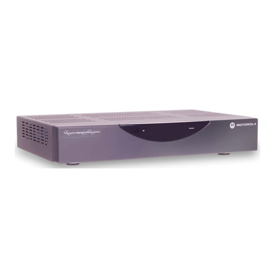
Page 8: Figure 1-1 Dct1800 Advanced Set-Top
Section 1 Introduction The Motorola DCT1800 is an analog/digital set-top that supports 64 and 256 QAM digital signal formats. The DCT1800 is compatible with existing Motorola analog and digital set-top products. The Motorola DCT1800 offers: 54 through 860 MHz integrated tuner ®... -
Page 9: Using This Manual
Introduction Using This Manual This manual provides instructions to install and configure a DCT1800: Section 1 Introduction provides a product description, a list of related documentation, the technical helpline telephone number, and the repair/return procedure. Section 2 Overview describes the DCT1800 and provides an overview of its use. This section also identifies the front-panel displays and switches and describes the rear-panel features. -
Page 10: If You Need Help
24 hours per day, 7 days per week. Calling for Repairs If repair is necessary, call the Motorola Repair Facility at 1-800-227-0450 for a Return for Service Authorization (RSA) number before sending the unit. The RSA number must be prominently displayed on all equipment cartons. -
Page 11: Overview
Figure 2-1 illustrates the front panel: Figure 2-1 DCT1800 front panel The DCT1800 is operated by using the Motorola universal remote control. See “Remote Controls” in this section for information on operating the DCT1800. DCT1800 Installation Manual... -
Page 12: Rear Panel
Overview Rear Panel Figure 2-2 illustrates the rear panel of the DCT1800, which contains a power connection and connectors for video, audio, and RF cabling: Figure 2-2 DCT1800 rear panel AUDIO OUT VIDEO TV/VCR TO RF IN RF IN TV Pass Card CABLE IN Table 2-1 describes each of the rear-panel features: Table 2-1... -
Page 13: Remote Controls
Overview Remote Controls The DCT1800 uses a Motorola universal remote control to operate. If your system offers optional interactive applications, such as an interactive program guide, a different remote control may be required. The application provider should supply user instructions for each interactive application. -
Page 14: Table 2-2 Remote Control Keys
Overview Table 2-2 describes the remote control keys: Table 2-2 Remote control keys Item Description AUDIO, VCR/DVD, Selects a desired device to control. The selected mode will remain active CABLE, or TV until you press another device key. HELP Displays the help screen. POWER Turns the selected home entertainment component on or off. -
Page 15: Installing Batteries In Remote Control
NOTE! Use and dispose of batteries in accordance with all applicable laws, rules and regulations. Motorola will not be liable to anyone for the user's failure to use and/or dispose of batteries in the proper manner and in accordance with such laws, rules and regulations, or for any defect contained in batteries that may cause injury damage to persons or property. -
Page 16: Installation
Section 3 Installation This section provides instructions for installing and cabling the DCT1800. To complete the installation, you must: Connect the cables Supply power to equipment Download configuration information and software Run operational check and diagnostics This section also includes the procedure for performing a cold initialization of the DCT1800. Before You Begin Before you begin, review the installation instructions, gather the required items, and complete the tasks listed below:... -
Page 17: Standard Cabling Diagram
Installation Standard Cabling Diagram The DCT1800 will output on either channel 3 or 4 depending on the configuration message from the control system. Figure 3-1 illustrates a standard diagram connecting the DCT1800 to a TV using RF connectors: Figure 3-1 Standard cabling DCT1800 AUDIO OUT... -
Page 18: Standard Vcr Cabling Diagram
Installation Standard VCR Cabling Diagram Figure 3-2 illustrates the basic cabling diagram that enables you to record the channel being viewed: Figure 3-2 Standard VCR cabling DCT1800 AUDIO OUT VIDEO TV/VCR TO RF IN RF IN TV Pass Card CABLE IN From cable source AUDIO AUDIO... -
Page 19: Composite Baseband Cabling Diagrams
Installation Composite Baseband Cabling Diagrams Connecting the DCT1800 using the baseband RCA type outputs enables the subscriber to experience stereo and Dolby Surround sound when available on digital channels. Figure 3-3 illustrates the standard baseband audio and video outputs of the DCT1800: Figure 3-3 Standard baseband cabling DCT1800... -
Page 20: Figure 3-4 Composite Vcr Cabling
Installation Figure 3-4 illustrates baseband audio and video connections to a VCR and TV: Figure 3-4 Composite VCR cabling DCT1800 AUDIO OUT VIDEO TV/VCR TO RF IN RF IN TV Pass Card CABLE IN AUDIO CABLE IN VIDEO IN SVIDEO IN AUDIO CABLE OUT OUT L... -
Page 21: Stereo Cabling Diagram (Baseband)
Installation Stereo Cabling Diagram (Baseband) This audio configuration does not provide for a TV playing through the stereo. Figure 3-5 illustrates how to connect the DCT1800 to a stereo using the audio connectors on the VCR: Figure 3-5 Audio through the VCR DCT1800 AUDIO OUT VIDEO... -
Page 22: Figure 3-6 Audio Through Vcr/Audio Output On Tv
Installation This audio configuration enables the TV to play through the stereo. Figure 3-6 shows how to connect the DCT1800 to a stereo using the audio loop-through connectors on the VCR and the audio output ports on the TV monitor: Figure 3-6 Audio through VCR/audio output on TV DCT1800... -
Page 23: A/V Receiver Cabling Diagrams
Installation A/V Receiver Cabling Diagrams Using this configuration, the audio/video signals are passed through the digital receiver to enable the VCR record and playback features. Figure 3-7 illustrates audio/video connections for an A/V receiver: Figure 3-7 Audio through A/V Receiver DCT1800 AUDIO OUT VIDEO... -
Page 24: Operational Check
Installation Operational Check The operational check tests the communication link between the remote control and the DCT1800. The procedures verify the DCT1800 response to remote control commands. Table 3-1 lists the operational check procedures: Table 3-1 Operational check Feature Testing Procedure Power on Press to turn on the DCT1800. -
Page 25: Table 4-1 Troubleshooting Guidelines
This section provides information to assist you in quickly detecting, isolating, and resolving error conditions that might occur when using the DCT1800. If you need assistance, call the Motorola Technical Resource Center (TRC): Inside the U.S.: 1-888-944-HELP (1-888-944-4357) Outside the U.S.: 215-323-0044... -
Page 26: Specifications
Appendix A Specifications 54 - 860 MHz (excluding data carrier frequency) Input frequency Downloadable HRC/IRC frequency assignments 136 carriers per cable Number of channels: 1 channel per carrier Analog More than 1 channel per carrier, content dependent Digital 0 dBmV – +15 dBmV Input analog video level –17 dBmV –... - Page 27 Specifications 105 – 125, 60 Hz ac voltage 16 W at 115 Vac Power dissipation Provided on power supply and RF ports Surge protection 17.13 × 13.25 × 2.75 inches Size 8.6 pounds Weight DCT1800 Installation Manual...
-
Page 28: Diagnostics
All sample displays are illustrative; actual data will differ from the examples. The screens are available for V7.72 code and higher. Accessing Diagnostics Use the Motorola universal remote control to operate the DCT1800. To access and navigate the diagnostic mode: Press on the remote control to turn on the set-top. -
Page 29: Navigating The Diagnostics
Diagnostics Navigating the Diagnostics Figure B-1 illustrates the DIAGNOSTICS main menu: Figure B-1 DIAGNOSTICS Main Menu DIAGNOSTICS GENERAL STATUS OOB STATUS IN BAND STATUS AUDIO/VIDEO STATUS UNIT ADDRESS FIRMWARE VERSION CURRENT CHANNEL STATUS RENEWABLE SECURITY UPSTREAM MODEM APP CODE MODULES MEMORY CONFIG INTERACTIVE INFO MAC FREQUENCY TABLE... -
Page 30: D 01: General Status
Diagnostics d 01: General Status The general status diagnostic displays the error code, a short description of the error, the purchase count, and specific model information: Figure B-2 DCT1800 Status DCT1800 STATUS ERROR : E 00 NO ERROR PURCHASES Platform ID: : 0x0060 Family ID : 0x0000... -
Page 31: Error Codes
Diagnostics Table B-2 Diagnostic Main Menu Fields Field Description A sequence of LED flashes communicates errors when they occur. The Error Code Error Codes field displays the code for the active error when appropriate. The state of the set-top is connected or disconnected. The connected state of the Connected State set-top is set by a DCT-operations connect or disconnect message. - Page 32 Diagnostics Initialization Status Errors Code Flash Sequence Cause Remedy E 07 Repeating series of seven ROM verification failure Power cycle the set-top; if LED flashes, separated by repetitive, return for repair a pause Repeating series of eight Faulty RAM, ROM, EEPROM, or Return the set-top E 08 LED flashes, separated by...
-
Page 33: D 02: Out-Of-Band (Oob) Status
Diagnostics d 02: Out-of-Band (OOB) Status This diagnostic indicates the status of the out-of-band control channel. Figure B-3 OOB Diagnostic OOB DIAGNOSTIC DATA 23 dB GOOD EMM DATA CARRIER LOCK COUNT HUNT MODE None CUR FREQ EMM PRVDR ID 0x0001 Table B-4 OOB Diagnostic Fields Field... -
Page 34: Selecting The Oob Frequency
Diagnostics Field Description Indicates the current out-of-band frequency. CUR Freq Indicates the last known carrier (OOB frequency that had correct Provider ID). The ID of the provider of the Entitlement Management Message (EMM). EMM Provider ID Selecting the OOB Frequency To select the OOB frequency: From the OOB STATUS diagnostic, press the MENU button to enter the frequency selection mode. -
Page 35: D 03: In-Band Status
Diagnostics d 03: In-band Status The in-band diagnostics display for the last attempted channel tune. If a digital carrier is not present, the diagnostics indicate the carrier lock is analog. When the carrier lock is analog, all fields for digital (other than a carrier lock channel) are blank. Figure B-4 In-band Diagnostic IN BAND DIAGNOSTIC... - Page 36 Diagnostics Field Description Displays an estimate of the carrier signal-to-noise ratio. The SNR displayed is a measure of the QAM cluster variance, which is proportional to the SNR. Analog channels display analog for carrier lock. The SNR displays a number for the numeric value and blank for the ssss value.
-
Page 37: D 04: Audio/Video Status
B-10 Diagnostics d 04: Audio/Video Status This diagnostic displays the audio and video information for the current tuned channel. Figure B-5 Audio/Video Status AUDIO/VIDEO STATUS ADP Lock Audio Mode STEREO Audio SPDIF VP Lock MPEG Method MUTE BLACK Table B-6 Audio Video Status fields Status Description... -
Page 38: D 05: Unit Address
Diagnostics B-11 d 05: Unit Address This diagnostic displays the 16-digit (40-bit) unit address of the set-top. On the unit address OSD, the unit, network, and TV PassCard (TVPC) addresses are in decimal form (13 address digits and three check digits). The multicast 16-bit address is in TCP/IP decimal byte form. -
Page 39: D 06: Firmware Version
B-12 Diagnostics Field Description The Multicast 16 address numbers change to display the values for each data Multicast 16 Address stream. The following is a list of Multicast 16 addresses: DWLD DATA POLL This value represents the health of the set-top and should be 0xFF. If it is not Seed Health 0xFF, see the “Troubleshooting”... -
Page 40: D 07: Current Channel Status
Diagnostics B-13 d 07: Current Channel Status This diagnostic displays the instantaneous status of the last attempted channel tune on the in-band tuner. The status shows channel type (analog/digital), acquisition state, purchasable indicator, preview indicator, parental control status, and mute status. Figure B-8 Current Channel Status CURRENT CHANNEL STATUS... -
Page 41: Table B-8 Current Channel Status Fields
Indicates whether the current or next program can be purchased (YES or NO). Purchasable Indicates whether the current or next program has been bought (YES or NO). Purchased For Motorola use only. EPOCH Number For Motorola use only. EPOCH Type For Motorola use only. -
Page 42: Current Channel Variables
Diagnostics B-15 Current Channel Variables Table B-9 lists the CURRENT CHANNEL STATUS variables: Table B-9 Current Channel Status Variables OSD Variable State Analog − blank For digital only: ENC − encrypted UNE − unencrypted Current epoch authorization reason in the current_epoch_auth_reason field. This is displayed in hex: missing program re-key missing working key epoch message... -
Page 43: D 08: Renewable Security System
B-16 Diagnostics d 08: Renewable Security System The renewable security system includes a TVPC card that returns the security status to current. Figure B-9 Renewable Security RENEWABLE SECURITY TVPC NOT REQUIRED CRYPTO NOT MATED STATUS VERSION Table B-10 Renewable Security Fields Field Description Indicates whether further operation of the set-top requires the TVPC. -
Page 44: D 09: Upstream Modem (Starvue Ii Diagnostics
Diagnostics B-17 d 09: Upstream Modem (STARVUE II Diagnostics) This diagnostic shows the status and operating parameters for the STARVUE II RF return. Figure B-10 STARVUE II Diagnostic STARVUE II DIAGNOSTICS STATUS: DISABLED FREQUENCY: 23.000 MHz LEVEL: IPPV: DISABLED LAST POLL REQ: 6-15-2001 20:49:33 LAST POLL ACK:... -
Page 45: D 10: Application (App) Code Modules
B-18 Diagnostics d 10: Application (APP) Code Modules This diagnostic displays the currently downloaded code modules. This can be a multi-page display. Press to display additional pages. Figure B-11 SELECT is an example of an OSD screen for a set-top that contains ROM: Figure B-11 APP Code Modules APP CODE MODULES... -
Page 46: D 11: Memory Status
Diagnostics B-19 d 11: Memory Status This diagnostic displays the DCT1800 memory status. The format of the OSD depends on the installed memory types. Figure B-12 Memory Status MEMORY STATUS EEPROM VER.NO. 00.00 PLATFORM APPLICATION NVMEM 236k DRAM 512k 1.5M FLASH 768k 1.25M... -
Page 47: D 12: Interactive Info
B-20 Diagnostics d 12: Interactive Info The INTERACTIVE INFO menu is a diagnostic tool used to gather data about your system: Figure B-13 Interactive Info INTERACTIVE INFO 0.0.0.0 0X000021 UPSTREAM ID 0X0000 DOWNSTREAM ID 0X0000 STATE UNCONFIG MAC ABORT CNTR 0000 GOOD PACKETS: ERROR PACKETS:... -
Page 48: D 13: Mac Frequency Table
Diagnostics B-21 Field Description State The state modes are: MAC CONNECT UNCONFIG INIT_WAIT_DC_OR_ WAIT_LM_ACK WAIT_SO_ACK WAIT_LA_OR_SO INIT_STOPPED RUN_WAIT-DC-OR-C RUNNING RUN_STOPPED INVALID The MAC Abort Counter increments every time the MAC layer reaches the Cell Abort MAC Abort Cntr Count limit. The MAC Abort Counter is reset by the successful upstream transmission of a cell, for example, when an ACK is received by the set-top. -
Page 49: D 14: Message Types
B-22 Diagnostics Table B-15 MAC Frequency Table Fields Field Description Indicates the frequency, in Hz, for an upstream channel. Frequency Indicates the power level, in dBmV, used on a particular upstream channel to send Power data to the RPD. d 14: Message Types This diagnostic displays a listing of PIDs and counts. -
Page 50: D 15: In-Band Program Association Table (Pat
Diagnostics B-23 d 15: In-band Program Association Table (PAT) This diagnostic displays the Program Association Table Information. (For Motorola use only.) Figure B-16 In-band PAT IN BAND PAT (hex data) 0001 0029 d 16: In-band Program Map Table (PMT) This diagnostic displays the Program Map Table information. (For Motorola use only.) -
Page 51: D 18: In-Band Multicast Address Filter
B-24 Diagnostics d 18: In-band Multicast Address Filter This diagnostic displays in-band multicast filter information: Figure B-19 In-band Multicast Address Filter IN BAND MULTICAST ADDRESS FILTER Filter Table: DMCA 0000 0000 0000 0000 0000 0000 0000 0000 0000 0000 0000 0000 0000 0000 0000... -
Page 52: D 19: Keyboard / Led Diagnostics
Diagnostics B-25 d 19: Keyboard / LED Diagnostics This diagnostic does not apply to the DCT1800: Figure B-20 Keyboard / LED Diagnostics KEYBOARD / LED DIAGNOSTICS < > Î DCT1800 Installation Manual... - Page 53 Visit our website at: www.motorola.com 505975-001 03/03 MGBI...
Need help?
Do you have a question about the Digital Consumer Terminal DCT1800 and is the answer not in the manual?
Questions and answers