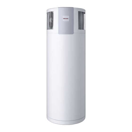
STIEBEL ELTRON WWK 300 AH Operation And Installation
Dhw heat pump
Hide thumbs
Also See for WWK 300 AH:
- Operation and installation (20 pages) ,
- Operation & installation manual (20 pages) ,
- Operating and installation instructions (16 pages)
Summary of Contents for STIEBEL ELTRON WWK 300 AH
- Page 1 OperatiOn and installatiOn dHW Heat pump » WWK 300 a » WWK 300 ap » WWK 300 aH » WWK 300 aHp...
-
Page 2: Table Of Contents
Correct operation ������������������������������ 3 Incorrect operation ���������������������������� 3 Function description ��������������������������� 3 Operation with active defrost feature WWK 300 A and WWK 300 AH ��������������� 3 Operation with passive defrost feature WWK 300 AP and WWK 300 AHP ������������ 3 Installation instructions for contractors ���5 Regulations and standards �������������������... -
Page 3: Operating Instructions For Users And Contractors
The Stiebel Eltron domestic hot water Heat pump operation defrost feature heat pump WWK 300 A/AP/AH/AHP WWK 300 A and WWK 300 AH This is the standard operating mode, (DHW) is a DHW generator that operates Subject to the relative humidity and the... -
Page 4: Troubleshooting By The User
Maintenance and cleaning 1.9 Troubleshooting by the user The device is generally maintenance No hot water free, with the exception of cleaning the Should you fail to obtain hot water at any condensate drain. time, you can take the following steps to A damp cloth is sufficient for cleaning remedy that situation. -
Page 5: Installation Instructions For Contractors
Installation instructions for contractors Regulations and standards The following standards were taken into Also observe the following: account: installation (water and electrical z The z The equipment type plate work) and commissioning, as well as AS 4234, AS 3498, AS 4020, AS 1056.1 z The specification the maintenance of this equipment, AS/NZS 2712, AS/NZS 3350.2.40/30/30.2... -
Page 6: Installation
Installation utilisation of waste heat, for example from a boiler, tumble drier or Transport refrigerator/freezer. To protect the equipment against — The available floor area in the damage, it must be transported vertically installation room must be at least inside its dedicated packaging. Where 6 m². -
Page 7: Power Supply
If required install a condensate pump. For the connection to the power supply the fitted supply cord has to be used. (Fig. 3 and 4, pos. 2) WWK 300 A/WWK 300 AH: 10 High limit safety cut-out Electric booster heater Capacitor (only for the WWK 300 AH) -
Page 8: Commissioning
WWK 300 AP/WWK 300 AHP: 10 High limit safety cut-out Electric booster heater Capacitor (only for the WWK 300 AHP) Electrical cable 11 Electric booster heater (only for the WWK 300 AHP) Strain relief 12 Protective anode Power terminals 14 Safety high pressure limit Frost monitor 15 Condensate pan drain Heat pump control thermostat... -
Page 9: Safety Equipment And Maintenance
Safety equipment and installing the anode, ensure that the z Draining the cylinder: metallic conductor connection is correctly — Close the shut-off valve in the cold maintenance made. It’s recommended for first anode water supply. Only qualified contractors must carry out inspection to happen one year after —... - Page 10 Abtaubetrieb WWK 300 A Kältekreis Schemata Operation with active defrost feature WWK 300 A and WWK 300 AH Heizbetrieb Heating operation Defrost operation >P >P Luft Valve powered Valve powered Valve not powered = closed Valve not powered = closed WWK 300 AP Kältekreis Schemata...
- Page 11 Wiring diagram WWK 300 A F2 Compressor motor protection (Klixon) F3 High limit safety cut-out M1 Compressor M2 Fan N0 Heat pump control thermostat N2 Frost monitor V1 Solenoid valve V2 Solenoid valve X0 Power terminals X1 Heat pump terminals...
- Page 12 Wiring diagram WWK 300 AP F2 Compressor motor protection (Klixon) F3 High limit safety cut-out M1 Compressor M2 Fan N0 Heat pump control thermostat N2 Frost monitor X0 Power terminals X1 Heat pump terminals X2 Anode terminal earth Z1 Capacitor Fig.
- Page 13 Wiring diagram WWK 300 AH -7 °C / +3 °C T < T > N L PE 3 x 1,5 22,4 bar N L PE P > E1 Electric booster heater N1 Control thermostat, electric booster heater F1 High limit safety cut-out N2 Frost monitor Electric booster heater V1 Solenoid valve...
- Page 14 Wiring diagram WWK 300 AHP gnge -7 °C / +3 °C T < T > 22,4 bar P > gnge N L PE gnge 3 x 1,5 gnge N L PE E1 Electric booster heater N0 Heat pump control thermostat F1 High limit safety cut-out N1 Control thermostat, electric booster heater Electric booster heater...
-
Page 15: Specification
Specification WWK 300 ap WWK 300 aH WWK 300 a WWK 300 aHp 227069 227070 222422 227071 Outputs to EN 14511 Heating output L15/F70/W55 Power consumptions to EN 14511 Power consumption - booster heater 1.69 1.69 Power consumption L15/F70/W55 Coefficients of performance to EN 14511... -
Page 16: Warranty
In the event of any claim being made under the war- ranty, it is the original purchaser's responsibility to provide evidence of Stiebel Eltron (Aust) Pty Ltd warrants the domestic range of heat pump purchase and date of purchase. - Page 20 Deutschland Verkauf Tel. 0180 3 700705* | Fax 0180 3 702015* | info-center@stiebel-eltron.de STIEBEL ELTRON GmbH & Co. KG Kundendienst Tel. 0180 3 702020* | Fax 0180 3 702025* | kundendienst@stiebel-eltron.de Dr.-Stiebel-Straße | 37603 Holzminden Tel. 05531 702-90015 Tel. 05531 702-0 | Fax 05531 702-480 Ersatzteilverkauf Tel.


Need help?
Do you have a question about the WWK 300 AH and is the answer not in the manual?
Questions and answers