Table of Contents
Advertisement
Quick Links
Advertisement
Table of Contents

Related Manuals for Vimar 1955


Summary of Contents for Vimar 1955
- Page 1 Instructions manual 01955 Video door entry for Two-Wire call system by Elvox...
-
Page 3: Table Of Contents
Table of Contents Technical characteristics …………………………………………………………………………………………………………… Type of system …………………………………………………………………………………………………………………… Advantages of the Elvox …………………………………………………………………………………………………………… 3 Main technical characteristics of the system …………………………………………………………………………………… 4 Description of terminals …………………………………………………………………………………………………………… 4 Power input ………………………………………………………………………………………………………………………… 7 Operation of the Elvox ……………………………………………………………………………………………………………… 7 Power Supplies and other Elvox ………………………………………………………………………………………………… 7 General information on the digital controls ………………………………………………………………………………………... -
Page 4: Technical Characteristics
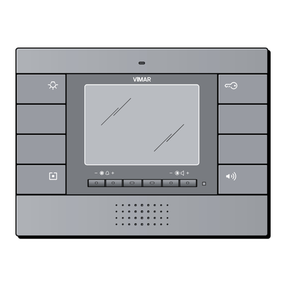
The video door entry module is none other than an audio-video interface through which it is possible to make voice and images interact; the device is provided with inputs and outputs that enable connecting the video door entry unit with the other appliances in the system (power supply, electrical lock, etc.). Figure 1 - Video door entry module 01955. -
Page 5: Type Of System
Type of system. The video door entry module 01955 can be used solely on video door entry systems of the Elvox Two Wire digital type; it will therefore be necessary to use solely Elvox power supplies in the Elvox Two Wire range (for the speci- fications see the relevant Elvox manuals). -
Page 6: Main Technical Characteristics Of The System
692I (or usb 692I/ U) and “SAVEPROG” software. Description of terminals. The video door entry unit has a 8 connector for connecting the audio and video signals, power supplies, callsand all the optional functions. 01955 VIDEOCITOFONO DUE FILI 2 - WIRES VIDEO ENTRY PHONE Figure 2... - Page 7 Technical characteristics The connector, on the pillar side, through which all the connections from and to the video door entry unit are made, has 8 terminals (inputs and outputs) divided according to the functions described in the table on the following page.
- Page 8 Technical characteristics Figure 4 - Hooking onto the bracket Figure 5 - Unhooking from the bracket Figure 6 - Removing the video door entry unit...
-
Page 9: Power Input
Technical characteristics Power input. The consumption of the video door entry 01955 depends on the current operating mode of the video door entry unit (standby, on call, red/green LED on, control activation, etc.). The mean values of the power input in the three typical modes of operation are the following: - on standby 6 mA. -
Page 10: General Information On The Digital Controls
Technical characteristics General information on the digital controls. The digital controls are packets of data that can be sent from/to each digital device and contain the information/ instructions that enable activating a particular function (video call, intercom call, lock opening, stair lighting, auxiliary function activation, etc.) . -
Page 11: Functions Of The Video Door Entry Unit
Functions of the video door entry unit The main function of the device is to identify, with communication and viewing via the audio and video channels, people asking to access the dwelling from the speech unit and to open or not open the electrical lockof the gate or door. In addition, the video door entry unit enables implementing other additional functions that are: - activating stair lights;... -
Page 12: The "Tv" (Termination Video) Line Termination Selector
B termination 100 Ohm if the bus terminates in the device position C termination 50 Ohm alternative to position B 01955 VIDEOCITOFONO DUE FILI 2 - WIRES VIDEO ENTRY PHONE 1 C A Figure 7 - "TV" line termination selector... -
Page 13: The "Second Function" Button (2Ndf)
"C" button on the monitor as the “second function” (2ndf) button. 01955 VIDEOCITOFONO DUE FILI 2 - WIRES VIDEO ENTRY PHONE... -
Page 14: Warnings For Device Coding And Programming
Functions of the video door entry unit The 2ndF button, pressed in combination with other buttons, sends further separate additional commands on the digital line. When button "C" is configured as 2ndF the correspondence between command - button is the following: LOCK Pressing button "B"... -
Page 15: Device Programming Phases
Functions of the video door entry unit Device programming phases. For the correct configuration and programming of the system, follow this procedure in sequence: - Install and connect all the system devices - For video door entry systems, set the jumper for video termination as shown on the connection diagrams - If present in the system code the Elvox devices 692S, 69RH, 692U, 692U/C, 69AV, 69AM, 69AU - When there are electronic entrance panels with pushbuttons, do the hardware programming of any pushbutton modules... - Page 16 Functions of the video door entry unit Figure 11 Figure 10 • Briefly, using a screwdriver or a small tool, press the push button R below the button "C" (figure 10); • Press and hold down the button "B" for at least 3 seconds (door opening function) (figure 11); •...
-
Page 17: Secondary Numerical Coding Of The Video Door Entry Unit - Group Call
Functions of the video door entry unit Secondary numerical coding of the video door entry unit Programming the secondary identification code is only required when you want to have more than one video door entry unit ring at the same time with the same push-button or call code. The video door entry units that must ring at the same time are associated with the same group;... -
Page 18: Self-Start Function
Functions of the video door entry unit Self-start function This function enables activating audio and video communication on the speech unit without a call being received; this can be useful, for instance, in the case in which it is wished to check the external zone or an internal zone where an additional video camera has been installed. -
Page 19: Door Open" Indicator
Functions of the video door entry unit “Door Open” indicator. This function enables displaying a “Door Open” signal on the video door entry unit by lighting up the green LED on the right-hand side of the LCD monitor; this application is useful to avoid unwanted access to the housing unit. To enable this function it is necessary, when the door is closed to connect a sensor with a N.O. -
Page 20: Lock Control Activation
Functions of the video door entry unit LOCK command activation. This command opens the lock of the door or the gate that provides access to the housing unit. The command is made by pressing the button "B" that sends the LOCK command to the panel which activates the corresponding actuator. -
Page 21: Stair Lights Control Activation (Function-F1/F2 Or Aux Service 1/2)
Functions of the video door entry unit Stair lights control activation (FUNCTION-F1/F2 or AUX SERVICE 1/2). With this command it is possible to activate the output used for commanding a suitable external relay connected to one or more lamps to be turned on. To activate this type of service it is possible to use both the FUNCTION F1/F2 commands (actuators available directly on the panel and common to all the internal ones) or the AUX 1/2 SERVICE commands (up to a max of 16 independent services) with the support for an Elvox external digital relay art. -
Page 22: Auxiliary Function Activation (Function-F1/F2 Or Aux Service 1/2)
Example of installation CP - N/O Call button 01955 VV-Video Door Entry Unit 01955 Figure 17 - Doorbell calls... -
Page 23: Landing Calls
Entrance panel AL - Elvox Power Supply Art. 6922 SP - Elvox separator Art. 692S CP - Landing call button Art. 20577/14577 NT - Network Figure 18 - Landing calls, audio only VV - Video Door Entry Unit Art. 01955... - Page 24 TC - Video camera with microphone Art. 20565/14565 Figure 19 - Landing calls, audio/video VV - Video Door Entry Unit Art. 01955 NT - Network For further details on the connections, see the technical documentation of the single articles (call button, video...
-
Page 25: Installation Of Supplementary External Ringtones
Examples of installation: SN - Elvox bell Art. 860A AR - Bell power supply NT - Network SS - Additional ringtone VV-Video Door Entry Unit Art. 01955 Art. 170A/101 Art. 860A 01955 4 5 7 8 C 1 2 15... - Page 26 Art. 6922 AL1 - Elvox Power Supply Art. 6923 AL2 - Elvox Power Supply Art. 6922 M - Pillar NT - Network VV - Video Door Entry Unit Art. 01955 Figure 22 - Video door entry units with simultaneous video calls...
-
Page 27: Installation Topology
AL - Elvox Power Supply Art. 692D/2 TE - Elvox video external entrance panel Art. 89F5..., 89F7..., 89F5/C..., 89F7/C K - Landing call button SE - Electric lock 12 Vdc VV-Video Door Entry Unit Art. 01955 Figure 23 - Video door entry system 2 indoor stations... - Page 28 K - Landing call button CV - Audio Door Entry Unit Art. 20557/14557 VV - Video Door Entry Unit Art. 01955 Figure 24 - Video door entry system multi-family In the above examples, there is a single main power supply (AL) in the systems that use the single outdoor station (TE);...
- Page 29 Installation topology In the system pillar there can be installed both Vimar and Elvox (VV, VE, CE) indoor stations, provided that these belong solely to the Elvox Two Wire system range. For the technical details on the possible installation topologies both in the standard residential sector and in the building structure complex, see the examples given in the attached diagrams “INSTALLATION EXAMPLES AND...
- Page 30 Art. 6309, 6309/C, 6009+6209+6145, 6009/C+6200+6145 K - Landing call button SE - Electric lock 12 Vdc CV - Audio Door Entry Unit Art. 20557/14557 VV - Video Door Entry Unit Art. 01955 Figure 26 - Video door entry system in building complex...
-
Page 31: Configuration Of The Video Door Entry Unit
Configuration of the video door entry unit Configuration of the video door entry unit. All the main standard functions of the video door entry unit seen in the chapter “FUNCTIONS OF THE VIDEO DOOR ENTRY UNIT” are configured with the buttons on the front of the device (see fig. 6 ); for the advanced programming of the video door entry unit (optional functions such as setting groups, association of buttons with specific commands, configuration of the intercom calls, association with the landing audio/video call buttons, etc.) it is necessary to use the Elvox programmable time switch 950C or the PC and the serial interface 692I (or usb... -
Page 32: Landing Calls, Audio Only
Configuration of the video door entry unit Red LED indicators. When the "User Away” function is enabled, the LED supplies the following information: • LED on steady = "User Away” function enabled. • LED flashing at brief intervals = Call received (the LED emits up to 4 rapid flashes to distinguish up to 4 different calls received). - Page 33 Configuration of the video door entry unit IMPORTANT: The video/audio door entry unit can be associated with up to a maximum of 4 different landing call buttons; the identification code of the call button belongs to the class of the monitors (numerical code from 1 to 200).
- Page 34 CP - Landing call button Art. 20577/14577 K - Landing call button CV - Audio Door Entry Unit Art. 20557/14557 SE - Electric lock 12 Vdc TC - Video Camera Art. 20560/20565 VV - Video Door Entry Unit Art. 01955...
-
Page 35: Audio/Video Interface For Video Cameras
Configuration of the video door entry unit Audio/video interface for video cameras The audio/video interface for video cameras art. 69AM Elvox is a DIN bar 8-module device necessary to make both the audio/video landing call and self-start any additional video cameras installed in the system with “CCTV function.”... - Page 36 Configuration of the video door In this way the interface behaves exactly as a normal SLAVE panel; to switch on the first video camera it is necessary to repeatedly send the SELF-START command from the video door entry unit (see the chapter “SELF- START FUNCTION“) so as to “scroll”...
-
Page 37: Ringtone Type Selection
Configuration of the video door entry unit 2. Use of the interface 69AM for audio/video landing calls If there is a landing audio/video speech unit (push-button 20577/14577 and video cameras 20560, 20565, 14560, 14565), the audio/video interface can be used instead without numerical coding of the secondary panel as instead was necessary in the preceding case (in this way an ID reserved for the class of panels is not pointlessly occupied). -
Page 38: Ringtone Volume Adjustment
Configuration of the video door entry unit ringtone and wait for the red LED to flash after setting. The landing call ringtone can also be set through the advanced programming of the video door entry unit; in this case it is necessary to use the programmable time switch 950C or a PC and the serial interface 692I (or usb 692I/U) with Elvox “SAVEPROG”... - Page 39 Configuration of the video door entry unit Setting the video parameters. With the following procedures it is possible to set the three parameters that control the video picture on the LCD monitor: - brightness; - contrast; - colour. Setting the brightness. To set the degree of brightness of the LCD monitor it is necessary, with the MONITOR ON, to perform the fol lowing operations: •...
-
Page 40: Direct Configuration Of Push-Buttons (E.g. Intercommunicating Calls)
Configuration of the video door entry unit Direct configuration of push-buttons (INTERCOM CALLS). The buttons on the video door entry unit can be configured for sending different specific commands on the bus. They can be configured, for instance, for sending FUNCTION F1/F2 commands, the self-start command on a specific panel, the command for making an intercom call, etc…... -
Page 41: Configuration Of The Optional Functions Of The Video Door Entry Unit (Advanced Programming With "Saveprog")
P0. .P8: Figure 32 - Correspondence of buttons CORRESPONDENCE BETWEEN SAVEPROG CORRESPONDENCE BETWEEN SAVEPROG AND VIMAR MONITOR 01955 WITHOUT 2ndF AND VIMAR MONITOR 01955 WITH 2ndF SAVE PROG Button 01955 Function SAVE PROG Button 01955 Function LOCK LOCK... -
Page 42: Pushbutton Programming
Configuration of the video door entry unit Programming the buttons (INTERCOM CALLS) The push-button function programming can be done by directly using the programmable time switch 950C or the interface 692I (or usb 692I/U) for PC and Elvox software “SAVEPROG” without operating on the device with direct programming. -
Page 43: Setting The Flags
Enables the hands-free ON/OFF function (“Hand Free”) Forza Sec.F. Forces the SELF-START button as 2ndF Dom. VIMAR Sets the VIMAR home automation system Grp. Escl. S. If on “User Away,” the secondary ones ring all the same I.C. Illim. Unlimited duration of intercom conversations Example di flag configuration with “SAVEPROG”:... -
Page 44: Setting The Group Calls
Configuration of the video door entry unit Setting the group calls Besides directly setting the secondary identification code (see the chapter "SECONDARY NUMERICAL CODING OF THE VIDEO DOOR ENTRY UNIT" of this manual) that enables inserting the video door entry unit in a group of devices (audio/video door entry units) that at the same time receive a call, this association can also be made via advanced programming with programmable time switch 950C or interface 692I (or usb 692I/U) for PC and Elvox “SAVEPROG”... -
Page 45: Associating Landing Calls
Configuration of the video door entry unit Associating landing calls Via advanced programming with the programmable time switch 950C or interface 692I (or usb 692I/U) per PC and Elvox “SAVEPROG” software, it is possible (in the specific field that can be filled in with the above-mentioned instruments for advanced programming) to set the landing call buttons from which the video door entry unit is able to receive a call. -
Page 46: Setting And Adjusting Ringtones
Configuration of the video door entry unit Setting and adjusting ringtones Via advanced programming with the programmable time switch 950C or interface 692I (or usb 692I/U) per PC and Elvox “SAVEPROG” software, it is possible to set the ringtones of the different incoming calls to the video door entry unit (from panel, landing call or intercom call) to differentiate the ringtone so as to recognize them audibly. -
Page 47: Setting The Video Parameters
Configuration of the video door entry unit Setting the video parameters Via advanced programming with the programmable time switch 950C or interface 692I (or usb 692I/U) for PC and Elvox “SAVEPROG” software, it is possible to set the video control levels (brightness and contrast) of the LCD monitor of the video door entry unit. -
Page 48: Resetting The Configurations
Configuration of the video door entry unit Resetting the configurations Deleting all settings. This procedure is recommended if you want to modify the ID of a video door entry unit previously programmed and without keeping the programming for operation of the device: 1) Press and hold the “R”... -
Page 49: Programming The Elvox
Programming the Elvox Programming the Elvox WARNING! The following operations must be carried out after powering up the system and before pro- gramming the audio door entry units and video door entry units. In the same system there must be only one MASTER panel (identification code 1) while any secondary panels must be set as SLAVES (see the technical documentation related to the particular panel used). -
Page 50: Example Of Technical Parameters Of Panel
Programming the Elvox Example of technical parameters of panel Message language English Panel ringtone repeat Enabled Panel ID Monitor/audio door entry unit ring- Coding digit number Sequential tone cycles Lock code No association Common locks No association Push-button preferential code No association F1 common No association... -
Page 51: Standard Video Door Entry System Diagrams
Examples and installation diagrams Examples and installation diagrams • CONNECTION DIAGRAM FOR VIDEO DOOR ENTRY SYSTEM 1 VIDEO PANEL • CONNECTION DIAGRAM FOR VIDEO DOOR ENTRY SYSTEM 3 VIDEO PANELS • CONNECTION DIAGRAM FOR VIDEO DOOR ENTRY SYSTEM WITH INTERCOM ISLAND •... -
Page 52: Quick Guide To Using The Video Door Entry Unit
Quick guide to using the video door entry unit Table of the functions of the buttons on the flush-mounting monitor 01955 in the Elvox Two Wire system. Cases are distinguished in which the monitor is OFF or ON, that is if it is in operation after an external call from a panel, the landing, an intercom or after a self-start. -
Page 53: Installation Rules And Compliance With Regulations
Installation rules and compliance with regulations Installation regulations. Installation should be carried out observing current installation regulations for electrical systems in the country where the products are installed. Regulatory compliance. EMC directive Standards EN 61000-6-1, EN 61000-6-3. -
Page 54: Glossary
Glossary Glossary Entrance panel. Set of audio and video devices that allow identifying the party asking to enter the dwelling via the outdoor station. Indoor station. Single video door entry or only audio door entry device that enables identifying the person at the speech unit that made the call. - Page 58 Viale Vicenza, 14 I 36063 Marostica VI Tel. +39 0424 488 600 Fax +39 0424 488 739 907.1955A0.L.EN 01 0810 http://www.vimar.eu VIMAR - Marostica - Italy...
Need help?
Do you have a question about the 1955 and is the answer not in the manual?
Questions and answers