Table of Contents
Advertisement
Available languages
Available languages
Quick Links
1
2
ABC
4
5
GHI
JKL
7
8
PQRS
TUV
0
R
+
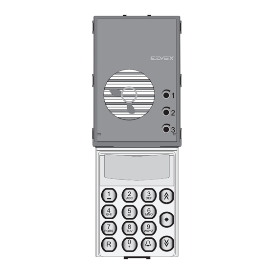
Unità elettronica video o audio con tastiera e display grafico per targhe
Video or audio electronic unit with keypad and graphic display for entrance panels
Manuale installatore - Installer guide
1
1
2
2
3
3
3
1
2
3
ABC
DEF
DEF
6
4
6
5
GHI
MNO
MNO
JKL
9
7
8
9
PQRS
TUV
WXYZ
WXYZ
0
R
+
1282
1282/P
1
2
3
1
2
3
1
2
ABC
ABC
DEF
4
6
4
5
5
GHI
GHI
JKL
MNO
JKL
7
8
9
7
8
PQRS
TUV
W
PQRS
TUV
WXYZ
0
0
R
R
+
+
1286
1286/P
1282, 1286
Advertisement
Table of Contents

Related Manuals for Vimar Elvox 1282


Summary of Contents for Vimar Elvox 1282
- Page 1 Manuale installatore - Installer guide PQRS WXYZ PQRS PQRS WXYZ PQRS WXYZ 1282 1286 1282/P 1286/P 1282, 1286 Unità elettronica video o audio con tastiera e display grafico per targhe Video or audio electronic unit with keypad and graphic display for entrance panels...
- Page 2 1282 -1286 UNITA’ ELETTRONICA Il manuale istruzioni è scaricabile dal sito www.vimar.com L’unità elettronica dispone di un posto esterno, di una telecamera (per le versioni video), di un display grafico retroilluminato, di una tastiera e di un Descrizione cablaggio per il collegamento della morsettiera.
-
Page 3: Operazioni Preliminari
1282 -1286 OPERAZIONI PRELIMINARI Morsettiera di collegamento (Solo per versioni 1282/P e 1286/P) Morsetti Descrizione Fig. 2 Le unità elettroniche 1282/P e 1286/P hanno l’opportunità di collegare dei Morsetto di comando per spegni- moduli pulsanti singoli fino ad un massimo di 31 pulsanti utilizzando i mo- mento monitor. - Page 4 1282 -1286 Esempi di configurazione targhe con pulsanti di chiamata PROGRAMMAZIONE HARDWARE DEI MODULI PULSANTI SUPPLE- Fig. 31 diretta aggiuntivi: MENTARI (Eseguire le modifiche con impianto spento) Se alla targa sono stati collegati dei moduli supplementari, è necessario programmarli. La programmazione dei moduli supplementari avviene tramite i dip – switch posti sotto il coperchio copri pulsante.
- Page 5 1282 -1286 MODALITA’ PER L’ACCESSO ALLE FUNZIONI DELLA ACCESSO AI MENU’ DI SETUP DELLA TARGA TARGA Per accedere ai menù di regolazione della targa, premere contemporanea- Premendo contemporaneamente due o più tasti è possibile accedere ai mente i pulsanti R + 4 ed inserire la password di programmazione tecnica sotto –...
- Page 6 1282 -1286 PARAMETRI DELLA TARGA I parametri della targa sono elencati nella tabella seguente: Parametro Min. Default Note Utent.Iniziale 99999999 Numero più piccolo delle utenze chiamate dalla targa Utente Finale 99999999 99999999 Numero più grande delle utenze chiamate dalla targa Numero Targa 99999999 Numero di identificazione della targa per chiamate da centralino.
- Page 7 1282 -1286 Parametro Min. Default Note Abil.Ch.Centralino Abilita la funzione di chiamata al centralino. Si utilizza quando la targa è una targa secondaria in un complesso edilizio: 0 = Chiamata centralino disabilitata 1 = Chiamata centralino da pulsante di chiamata diretta programmato in Par.
- Page 8 1282 -1286 Parametro Min. Default Note 1 Num. Memoria 99999999 Numero rapido di chiamata associato al tasto “ ”. 0 = non abilitato PQRS WXYZ 2 Num. Memoria 99999999 PQRS WXYZ Numero rapido di chiamata associato al tasto “ ”. 0 = non abilitato Volume esterno Volume del segnale dell’altoparlante della targa.
- Page 9 1282 -1286 DESCRIZIONE DELLE FUNZIONI E DEI PARAMETRI Codifica software (associazione Hardware – software) (7). (Da uti- lizzare solo per versioni 1282/P o 1286/P) E’ possibile eseguire la pro- Utente Iniziale (1) e Utente Finale (2). Questi parametri sono da pro- grammazione dell’associazione HW-SW dei pulsanti targa solo quando il grammare in caso di un impianto tipo complesso edilizio ed indicano l’in- parametro è...
- Page 10 1282 -1286 Fonica Attiva (21). Se questo parametro è uguale a 1, la targa si attiva “Abil. Serratura” Apre con: automaticamente quando la linea di fonica è caricata e la tensione di fonica è inferiore 7V. Nel caso di più targhe collegate in parallelo l’attivazione au- Conversazione in corso (1) tomatica delle targhe può...
- Page 11 1282 -1286 Trasmissione della chiave ricevuta “Tx Chiave” (57). Il codice della Attivazione del datalogger “Datalogger (R9)” (30). Se posto ad 1 si attiva chiave ricevuto da uno dei lettori trasponder collegati al canale digibus mon- il datalogger della targa. Il Datalogger registra i messaggi generati dalla tante citofoni, può...
- Page 12 1282 -1286 PROGRAMMAZIONE DEI CODICI CHIAVI Attenzione!: Se la targa è connessa in parallelo ad altre targhe con en- trambe le seriali (morsetti 1 e 6) è possibile abilitare i bit 5 e 6 solo su una Le chiavi software sono codici che permettono, a seconda della program- targa mentre sulle altre è...
- Page 13 1282 -1286 ASSOCIAZIONE HARDWARE – SOFTWARE - FASCE ORARIE. Ad ogni chiave possono essere associate 2 fasce ora- rie delle 16 disponibili e programmabili dal menù fasce orarie. (Solo per versioni 1282/P e 1286/P) Per modificare la fascia oraria selezionarla utilizzando i tasti PQRS WXYZ Ad ogni pulsante per chiamata diretta è...
- Page 14 1282 -1286 PROGRAMMAZIONE DELLE FASCE ORARIE PROGRAMMAZIONE ED USO DELLA RUBRICA Da questo menù si programmano le fasce orarie associate alle chiavi. Ogni Accesso al menù gestione rubrica fascia oraria è attivabile in uno o più giorni della settimana e dispone di due La targa gestisce una rubrica che può...
-
Page 15: Uso Della Rubrica
1282 -1286 Cancellazione di un utente inserito Dal menù “gestione rubrica” selezionare l’opzione 2. SPACE Si accede alla rubrica. PQRS WXYZ µ Selezionare l’utenza da cancellare scorrendo la rubrica con i tasti “ ” " e “ ” & Á Ď... -
Page 16: Electronic Unit
1282 -1286 ELECTRONIC UNIT The instruction manual is downloadable from the site www.vimar.com The electronic unit is equipped with a speech unit, camera (on video ver- sions), backlit graphic display, a keypad and wiring for terminal block con- nections. The 1282/P and 1286/P versions are also equipped with wiring for Description connection of additional push-button modules. -
Page 17: Terminal Block
1282 -1286 TERMINAL BLOCK PRELIMINARY OPERATIONS Fig. 2 Terminal Description (only for versions 1282/P and 1286/P) Electronic units type 1282/P and type 1286/P can be connected to individ- Monitor shutdown control terminal. ual push-button modules to provide up to a maximum of 31 push-buttons using the additional modules with push-buttons in single row, or up to 30 Electric lock activation control terminal. - Page 18 1282 -1286 PROGRAMMING THE HARDWARE OF ADDITIONAL Examples of configuration of entrance panels with addi- Fig. 31 tional direct call push-buttons: PUSH-BUTTON MODULES (make changes with system switched off) If additional modules have been connected to the entrance panel, they must be programmed.
-
Page 19: Quick Function Buttons
1282 -1286 THE PANEL SETUP MENUS PROCEDURE FOR ACCESSING ENTRANCE PANEL FUNC- TIONS To access the entrance panel setup menus, simultaneously press push-but- Simultaneously press two or more buttons to access the entrance panel tons R + 4 and enter the technical programming password (parameter 8), submenus listed in the following table: the default value is 123. - Page 20 1282 -1286 ENTRANCE PANEL PARAMETERS The entrance parameters are listed in the following table: Parameter Min. Default Notes Init.User 99999999 Lowest number of users called from the entrance panel Final User 99999999 99999999 Highest number of users called from the entrance panel Panel Number 99999999 ID number of the entrance panel for calls from switchboard.
- Page 21 1282 -1286 Parameter Min. Default Notes Switchbd button If the entrance panel is a secondary panel and parameter 19 = 1, when the direct call button with the same hardware code as the code programmed in this parameter is pressed, the entrance panel substitutes the called number with the entrance panel number (pa- rameter 3) and sends the call on the serial line to the main panel / main switchboard.
- Page 22 1282 -1286 Parameter Min. Default Notes 1 Memory Num. 99999999 Quick call number associated with the button “ ”. 0 = disabled PQRS WXYZ 2 Memory Num. 99999999 PQRS WXYZ Quick call number associated with the button “ ”. 0 = disabled Ext.1 Address 99999999 Address of external transponder reading device 1...
- Page 23 1282 -1286 DESCRIPTION OF FUNCTIONS AND PARAMETERS The number called by the entrance panel becomes 9100015. Initial User (1) and Final User (2). These parameters must be programmed in the case of a building complex type system and indicate the range of users Shift code “Sum Number”...
- Page 24 1282 -1286 Audio Active (21). If this parameter is equal to 1, the entrance panel acti- Lock activation mode “Enab. Lock” (15). This parameter configures the vates when the audio line is charged and the audio voltage is less than 7V. opening of the local door lock, e.g.
- Page 25 1282 -1286 Activate datalogger “Datalogger (R9)” (30). If set to 1 the entrance panel Tx Key Action: datalogger is activated. The datalogger records messages generated by the entrance panel or which are transmitted over the databuses connected Doesn’t transmit the key to the entrance panel (cable riser serial line and serial line to the main entrance panel) and can be displayed by simultaneously pressing buttons Transmits the key if it is present in the entrance panel data-...
- Page 26 1282 -1286 PROGRAMMING KEYCODES Caution: If the entrance panel is connected in parallel to other entrance panels with both serials (terminals 1 and 6) it is possible to enable bits 5 Software keys are codes which, depending on the programming operation, and 6 only on one entrance panel, whereas the others must be left disabled.
-
Page 27: Operating Modes
1282 -1286 HARDWARE – SOFTWARE ASSOCIATION • TIME BANDS. Each key can be associated with 2 time bands from a total of 16 available, which can be programmed from the time band menu. (Only for version 1282/P and 1286/P) PQRS WXYZ To modify the time band select it using the “... - Page 28 1282 -1286 PROGRAMMING TIME BANDS AGENDA PROGRAMMING AND USE The time bands associated with the keys are programmed from this menu. Each time band can be activated on one or more days of the week and has Accessing the agenda management menu two time windows, valid for days programmed weekly.
- Page 29 1282 -1286 Deleting an inserted user From the “agenda management” menu select option 2. The agenda opens. PQRS WXYZ PQRS WXYZ SPACE Select the user to delete by scrolling the agenda pressing “ ” and “ ” µ " The user to be deleted is highlighted by the “” symbol &...
- Page 30 1282 -1286 Sezione minima conduttori (in mm Minimal conductor section(mm Conduttori Ø fino a 50 m. Ø fino a 100 m. Ø fino a 200 m. Conductors Ø up to 50 m. Ø up to 100 m. Ø up to 200 m. 0,75 mm 1 mm 1,5 mm...
- Page 31 1282 -1286 IMPIANTO CONDOMINIALE SEMPLICE CON CITOFONI MUNITI DI DECODIFICA INTERNA. SIMPLE RESIDENTIAL ISTALLATION WITH INTERPHONES EQUIPPED WITH INTERNAL DECODING. Montante citofoni Interphone cable riser A1 - Citofono serie Petrarca 6204 A1.0 - Citofono serie Petrarca 62K4 A2 - Citofono serie 6600 6604/AU, 6704/AU A3 - Citofono serie 8870 887B, 887B/1 C0 -...
- Page 32 1282 -1286 IMPIANTO CONDOMINIALE SEMPLICE CON DERIVATORE DIGITALE AL PIANO SIMPLE RESIDENTIAL INSTALLATION WITH FLOOR DISTRIBUTORS EQUIPPED WITH INTERNAL DECODING. Montante citofoni A1.1 - Citofono serie Petrarca 6201 Interphone cable riser A3.1 - Citofono serie 8870 8877 C0 - Unità elettronica audio con tastiera e display 1282 CX - Targa audio F2 -...
- Page 33 1282 -1286 IMPIANTO CONDOMINIALE SEMPLICE CON DUE O PIÙ TARGHE IN PARALLELO SIMPLE RESIDENTIAL INSTALLATION WITH TWO OR MORE PANELS IN PARALLEL. Rif. schema si030 Ref. diagram si030...
- Page 34 1282 -1286 IMPIANTO CONDOMINIALE CON UNA TARGA PRINCIPALE E DUE O PIÙ TARGHE A PIÈ SCALA (complesso edilizio). RESIDENTIAL INSTALLATION WITH ONE MAIN PANEL AND TWO OR MORE SECONDARY PANELS (BUILDING COMPLEX). Montante citofoni Montante citofoni Interphone cable riser Interphone cable riser Rete Rete Mains...
- Page 35 1282 -1286 IMPIANTO CONDOMINIALE CON DUE O PIÙ TARGHE PRINCIPALI E DUE O PIÙ TARGHE A PIÈ SCALA (complesso edilizio). RESIDENTIAL INSTALLATION WITH TWO OR MORE MAIN PANELS AND TWO OR MORE SECONDARY PANELS (BUILDING COMPLEX). Montante citofoni Montante citofoni C0 - Unità...
- Page 36 1282 -1286 MONTANTE MONITOR CON APPARECCHI MUNITI DI DECODIFICA INTERNA DEL SEGNALE DIGITALE. MONITOR CABLE RISER WITH UNITS EQUIPPED WITH INTERNAL DIGITAL SIGNAL DECODING. N.B. L’ultimo distributore video deve Montante videocitofoni essere caricato con la resistenza da 75 Monitor cable riser Ohm collegata al morsetto V libero.
- Page 37 1282 -1286 MONTANTE MONITOR CON DISTRIBUTORE AL PIANO 949B MONITOR RISER WITH FLOOR DISTRIBUTOR 949B Montante videocitofoni N.B. L’ultimo distributore video deve Monitor cable riser essere caricato con la resistenza da 75 Ohm collegata al morsetto V libero. 75 ohm NOTE: The last video distributor must be loaded with a 75 Ohm resistor con- 75ohm...
- Page 38 1282 -1286 IMPIANTO CONDOMINIALE SEMPLICE CON VIDEOCITOFONI MUNITI DI DECODIFICA INTERNA SIMPLE RESIDENTIAL INSTALLATION WITH MONITORS EQUIPPED WITH INTERNAL DECODING. Montante videocitofoni N.B. L’ultimo distributore video deve Monitor cable riser essere caricato con la resistenza da 75 Ohm collegata al morsetto V libero. 75ohm 75ohm NOTE: The last video distributor must...
- Page 39 1282 -1286 IMPIANTO CONDOMINIALE SEMPLICE CON DERIVATORI AL PIANO MUNITI DI DECODIFICA INTERNA. SIMPLE RESIDENTIAL INSTALLATION WITH DISTRIBUTORS EQUIPPED WITH INTERNAL DECODING. 1 3 4 5 - + N.B. L’ultimo distributore video deve essere caricato con la resistenza da 75 75 ohm Ohm collegata al morsetto V libero.
- Page 40 1282 -1286 IMPIANTO CONDOMINIALE SEMPLICE CON DUE O PIÛ TARGHE IN PARALLELO SIMPLE RESIDENTIAL INSTALLATION WITH TWO OR MORE PANELS IN PARALLEL Rif. schema si037 Ref. diagram si037...
- Page 41 1282 -1286 IMPIANTO CONDOMINIALE CON UNA TARGA PRINCIPALE E DUE O PIÙ TARGHE A PIÈ SCALA (Complesso edilizio). RESIDENTIAL INSTALLATION WITH ONE MAIN PANEL AND TWO OR MORE STAIRWAY PANELS (BUILDING COMPLEX). Montante videocitofoni Montante videocitofoni Monitor cable riser Monitor cable riser Rete Rete V 1 3...
- Page 42 1282 -1286 IMPIANTO CONDOMINIALE CON UNA TARGA PRINCIPALE E DUE O PIÙ TARGHE A PIÈ SCALA (Complesso edilizio). RESIDENTIAL INSTALLATION WITH ONE MAIN PANEL AND TWO OR MORE STAIRWAY PANELS (BUILDING COMPLEX). Montante videocitofoni Montante videocitofoni Monitor cable riser Monitor cable riser Rete Rete V 1 3...
- Page 43 1282 -1286 IMPIANTO CONDOMINIALE CON DUE O PIÙ TARGA PRINCIPALE VIDEO E DUE O PIÙ TARGHE A PIÈ SCALA VIDEO O AUDIO INSTALLATION FOR BLOCK OF FLATS WITH TWO OR MORE MAIN VIDEO ENTRANCE PANELS OR MORE VIDEO OR AUDIO OUTDOOR ENTRANCE PANEL (BUILDING COMPLEX).
- Page 44 1282 -1286 AUDIO ENTRY PANEL VARIANTS VARIANTI CITOFONICHE: Connection of auxiliary functions F1 - F2 in systems equipped with internal Collegamento funzioni ausiliarie F1 - F2 in impianti muniti di decodifica interna decoding or without internal decoding. o senza codifica interna. In some cases, enabling the functions requires the addition of supplementary buttons L’abilitazione delle funzioni richiede, l’aggiunta di pulsanti supplementari e di and connections to be made in addition to the basic connections.
- Page 45 1282 -1286 Impianti videocitofonici con videocitofoni Impianti videocitofonici con muniti di decodifica interna. videocitofoni senza codifica interna. Monitors with internal coding Monitors without internal coding Montante videocitofoni Monitor cable riser All’alimentatore 6948 To power supply 6948 75ohm 1 3 4 5 - + 75 ohm 75ohm 75ohm...
- Page 46 1282 -1286 Varianti di collegamento dell’unita elettronica con moduli Wiring diagram for connection of Digibus sytem electronic entrance supplementari con cartello luminoso per 13 nomi 805N o per numero panel with keypad and additional numerical display with luminous civico 80PN name-tag for 13 names type 805N or for street number type 80PN.
-
Page 47: Installation Rules
1282 -1286 Il manuale istruzioni è scaricabile dal sito www.vimar.com The instruction manual is downloadable from the site www. vimar.com Installation rules Regole di installazione Installation should be carried out by qualified personnel in compliance with the current L’installazione deve essere effettuata da personale qualificato con l’osservanza delle regulations regarding the installation of electrical equipment in the country where the disposizioni regolanti l’installazione del materiale elettrico in vigore nel paese dove... - Page 48 Viale Vicenza 14 36063 Marostica VI - Italy www.vimar.com 49400619A0 02 2110...
Need help?
Do you have a question about the Elvox 1282 and is the answer not in the manual?
Questions and answers