Table of Contents
Advertisement
Smart Roller Shutter
Slat Shutter Door Opener
WARNING: IT IS VITAL FOR THE SAFETY OF ALL
PERSONS INSTALLING AND USING THIS OPENER TO
FOLLOW THE INSTALLATION INSTRUCTIONS AND
SAFETY WARNINGS. FAILURE TO COMPLY MAY RESULT
IN SERIOUS PERSONAL INJURY AND/OR PROPERTY
INSTALLATION MANUAL
DAMAGE AND FAILURE OF THE OPENER SYSTEM.
Advertisement
Table of Contents

Subscribe to Our Youtube Channel
Related Manuals for Smart Openers Smart Roller Shutter


Summary of Contents for Smart Openers Smart Roller Shutter
- Page 1 Smart Roller Shutter Slat Shutter Door Opener WARNING: IT IS VITAL FOR THE SAFETY OF ALL PERSONS INSTALLING AND USING THIS OPENER TO FOLLOW THE INSTALLATION INSTRUCTIONS AND SAFETY WARNINGS. FAILURE TO COMPLY MAY RESULT IN SERIOUS PERSONAL INJURY AND/OR PROPERTY INSTALLATION MANUAL DAMAGE AND FAILURE OF THE OPENER SYSTEM.
-
Page 2: Table Of Contents
Technical Specifications Warranty To the extent that they may be lawfully excluded, Smart Openers Pty Ltd hereby expressly excludes all conditions and warranties, statutory or otherwise, which may be implied by law as conditions or warranties of purchase of a Smart Openers Pty Ltd Door Opener. Smart Openers Pty Ltd hereby further disclaims... -
Page 3: Kit Contents
Important Safety Warnings Description The Smart Roller Shutter Opener described in this The Smart Roller Shutter Opener requires a 240V AC manual is designed for the automation of commercial slat 50Hz power input. The 24V DC motor can provide remote shutter doors. -
Page 4: Operating Controls
+24V Lock + Lock - Activity 2 + Activity 2 - Activity 1 + Activity 1 - DC Charger - DC Charger + 24V AC 24V Battery Motor 1 Motor 2 Back Up © June 2009 Smart Openers Pty Ltd... -
Page 5: Mechanical Installation
Beams on all installations. Remember the unit has mains voltage running through it 10. When installing the Smart Roller Shutter Opener, (electrocution hazard, fire hazard, etc). strictly follow all the instructions given in the instruction manual. If some points or procedures 4. -
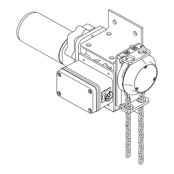
Page 6: Before Installation
4. The door must be properly balanced and must be easily moved by hand. 5. Install a 240V, adequately protected 3-pin socket near where the Smart Roller Shutter Opener is going to be installed. Side Room The minimum sideroom required is 265mm between the end of the output shaft and the wall. - Page 7 Fig. 4. 5. Ensure manual operation chain is seated properly in the hub wheel Fig. 5. Drive Sprocket Fig. 3a Hub Wheel Door Gear Drive Chain Manual Chain Drive Sprocket Fig. 5 Fig. 4 © June 2009 Smart Openers Pty Ltd...
-
Page 8: Electrical Connection
Electrical Connection Motor Connection Your Smart Roller Shutter Opener is equipped with a wiring harness with identical plugs at both ends. To connect the motor to the control box simply connect each end of the cable to the respective sockets on the drive motor and control box. -
Page 9: Initialising The Opener
MENU then press SET to confirm. The opener will now go into limits set up. Fig. 9 Note: To set limits via transmitter please refer to page 14 for Coding Transmitter instructions. Left Hand Installation Fig. 10 © June 2009 Smart Openers Pty Ltd... -
Page 10: Setting Limits
Set Ped Position. 2. Press and hold PB to move the door to the desired pedestrian open position. Fig. 15 3. Press SET to confirm. The door will now return to the closed position. -10- © June 2009 Smart Openers Pty Ltd... -
Page 11: Setting Pedestrian Mode
2. Close the door onto the timber. If the door does not reverse easily and attempts to continue to close adjust the force margin as per procedure above. 50mm Timber Fig. 18 -11- © June 2009 Smart Openers Pty Ltd... -
Page 12: Setting Motor Open/Close Speed
Photo Beam Mode allows the door to close once the M2 Open Limit beam has been tripped and restored. Smart Openers strongly recommend the installation of a PE safety beam M2 Close Limit to protect persons and property (Factory Default = Off). -
Page 13: Setting Auto-Close Mode
Close and Timer Delay If Pedestrian Mode is activated the above functions are also available for Pedestrian Mode. Follow the above procedure to enable auto-close and set a time delay as required. -13- © June 2009 Smart Openers Pty Ltd... -
Page 14: Coding Transmitters
Fig. 27 Transmitter Button Allocation Note: The Smart Roller Shutter is factory preset with TX Button 1 operating full access (PB) and Button 2 for Pedestrian Mode (PD). The following procedure PB PD OP CL alters these settings for all coded transmitters. -
Page 15: Manual Disengagement
User No particular maintenance is required for the logic circuit board. Once the Smart Roller Shutter Opener has been At least twice a year check that the door is properly installed, the user must be informed about how it works balanced, travelling smoothly and that all working parts and all the risks that can arise if it is used improperly. -
Page 16: Warranty
13. This warranty is not transferable. 14. Where the Product is retailed by any person other than Smart Openers , except for the warranty set out above, such person has no authority from Smart Openers to given any warranty or guarantee on Smart Openers behalf in addition to the warranty set out above.
Need help?
Do you have a question about the Smart Roller Shutter and is the answer not in the manual?
Questions and answers