Table of Contents
Advertisement
Quick Links
Advertisement
Table of Contents

Subscribe to Our Youtube Channel
Related Manuals for Supero SuperWorkstation 7036A-T


Summary of Contents for Supero SuperWorkstation 7036A-T
- Page 1 UPER ® 7036A-T uper orkstation USER’S MANUAL Revision 1.0...
- Page 2 The information in this User’s Manual has been carefully reviewed and is believed to be accurate. The vendor assumes no responsibility for any inaccuracies that may be contained in this document, makes no commitment to update or to keep current the information in this manual, or to notify any person or organization of the updates.
-
Page 3: About This Manual
SuperWorkstation 7036A-T. Installation and maintenance shall be performed by experienced technicians only. The SuperWorkstation 7036A-T is a dual processor system based on the SC733TQ- 665B mid-tower chassis and the Super X8DAL-i serverboard. Please refer to our web site for an up-to-date list of supported processors. - Page 4 UPER ORKSTATION 7036A-T User's Manual Chapter 5: Advanced Serverboard Setup Chapter 5 provides detailed information on the X8DAL-i serverboard, including the locations and functions of connectors, headers and jumpers. Refer to this chapter when adding or removing processors or main memory and when reconfi guring the serverboard.
- Page 5 Preface Notes...
-
Page 6: Table Of Contents
UPER ORKSTATION 7036A-T User's Manual Table of Contents Chapter 1 Introduction Overview ......................1-1 Serverboard Features ..................1-2 Processors ...................... 1-2 Memory ......................1-2 Serial ATA ....................... 1-2 PCI Expansion Slots ..................1-2 I/O Ports ......................1-2 Other Features ....................1-3 Chassis Features .................... - Page 7 Table of Contents Operating Precautions ..................4-4 Chapter 5 Advanced Serverboard Setup Handling the Serverboard ................5-1 Precautions ..................... 5-1 Unpacking ....................... 5-2 Serverboard Installation .................. 5-2 Connecting Cables ..................5-3 Connecting Data Cables ................. 5-3 Connecting Power Cables ................5-3 Connecting the Control Panel .................
- Page 8 Onboard Power LED (LE1) ..............5-21 5-12 SATA Ports ....................5-22 SATA Ports ....................5-22 5-13 Installing Software ..................5-23 Supero Doctor III ................... 5-24 Chapter 6 Advanced Chassis Setup Static-Sensitive Devices .................. 6-1 Precautions ..................... 6-1 Unpacking ....................... 6-1 Front Control Panel ..................6-2 System Fans ....................
- Page 9 Table of Contents Installing Components in the 5.25" Drive Bays ..........6-8 Power Supply ....................6-9 Chapter 7 BIOS Introduction ...................... 7-1 Starting BIOS Setup Utility ................7-1 How To Change the Confi guration Data ............7-1 Starting the Setup Utility ................. 7-2 Main Setup ......................
- Page 10 UPER ORKSTATION 7036A-T User's Manual Notes...
-
Page 11: Chapter 1 Introduction
Chapter 1 Introduction Overview The SuperWorkstation 7036A-T is a high-end workstation comprised of two main subsystems: the SC733TQ-665B mid-tower chassis and the X8DAL-i serverboard. Please refer to our web site for information on operating systems that have been certifi ed for use with the SuperWorkstation 7036A-T (www.supermicro.com). -
Page 12: Serverboard Features
ORKSTATION 7036A-T User's Manual Serverboard Features At the heart of the SuperWorkstation 7036A-T lies the X8DAL-i, a dual processor serverboard based on the Intel® 5500 chipset. Below are the main features of the X8DAL-i. (See Figure 1-1 for a block diagram of the chipset). -
Page 13: Other Features
Front Control Panel The control panel on the SuperWorkstation 7036A-T provides you with system monitoring and control. LEDs indicate power on, network activity, hard disk drive activity and overheat conditions. The control panel also includes a main power button and a system reset button. - Page 14 UPER ORKSTATION 7036A-T User's Manual Figure 1-1. Intel 5500/ICH10R Chipset: System Block Diagram Note: This is a general block diagram. Please see Chapter 5 for details. CPU 2 CPU 1 LGA1366 LGA1366 Port 1 Port 0 Gen2 Ports Intel 5500 Ports PCI32bit/33MHz Gen2...
-
Page 15: Contacting Supermicro
Chapter 1: Introduction Contacting Supermicro Headquarters Address: Super Micro Computer, Inc. 980 Rock Ave. San Jose, CA 95131 U.S.A. Tel: +1 (408) 503-8000 Fax: +1 (408) 503-8008 Email: marketing@supermicro.com (General Information) support@supermicro.com (Technical Support) Web Site: www.supermicro.com Europe Address: Super Micro Computer B.V. Het Sterrenbeeld 28, 5215 ML 's-Hertogenbosch, The Netherlands Tel:... - Page 16 UPER ORKSTATION 7036A-T User's Manual Notes...
-
Page 17: Chapter 2 System Setup
Unpacking the System You should inspect the box the SuperWorkstation 7036A-T was shipped in and note if it was damaged in any way. If the workstation itself shows damage, you should fi le a damage claim with the carrier who delivered it. -
Page 18: Setting Up The System
UPER ORKSTATION 7036A-T User's Manual • To maintain proper cooling, always keep all chassis panels closed and all SATA carriers installed when not being serviced. Setting Up the System You should fi rst open the left side panel (when facing the front of the chassis) to make sure the motherboard is properly installed and all connections have been made. - Page 19 Chapter 2: System Setup Figure 2-1. Accessing the Inside of the 7036A-T...
- Page 20 UPER ORKSTATION 7036A-T User's Manual See the installation and removal sections for the peripheral drives in Chapter Check the SATA disk drives: Depending upon your system's confi guration, your system may have up to four SATA drives already installed. If you need to install or remove an SATA drive, please refer to the appropriate section in Chapter 6.
-
Page 21: Chapter 3 System Interface
Chapter 3: System Interface Chapter 3 System Interface Overview There are several LEDs on the control panel and one on each SATA drive carrier to keep you constantly informed of the overall status of the system as well as the activity and health of specifi... -
Page 22: Control Panel Leds
UPER ORKSTATION 7036A-T User's Manual Control Panel LEDs The control panel located on the front of the SC733TQ-665BB chassis has four LEDs. These LEDs provide you with critical information related to different parts of the system. This section explains what each LED indicates when illuminated and any corrective action you may need to take. -
Page 23: Sata Drive Carrier Leds
Chapter 3: System Interface Check the routing of the cables and make sure all fans are present and operating normally. You should also check to make sure that the chassis covers are installed. Finally, verify that the heatsinks are installed properly (see Chapter 5). This LED will remain fl... - Page 24 UPER ORKSTATION 7036A-T User's Manual Notes...
-
Page 25: Chapter 4 System Safety
Chapter 4: System Safety Chapter 4 System Safety Electrical Safety Precautions Note: power should always be disconnected before perform- ing any service on the system. Basic electrical safety precautions shall be followed to protect yourself from harm and the SuperServer 7036A-T from damage: •... -
Page 26: General Safety Precautions
UPER ORKSTATION 7036A-T User's Manual • This product may be connected to an IT power system. In all cases, make sure that the unit is also reliably connected to Earth (ground). • Serverboard Battery: CAUTION - There is a danger of explosion if the onboard battery is installed upside down, which will reverse its polarites (see Figure 4-1). -
Page 27: Esd Precautions
Chapter 4: System Safety • Remove any jewelry or metal objects from your body, which are excellent metal conductors that can create short circuits and harm you if they come into contact with printed circuit boards or areas where power is present. •... -
Page 28: Operating Precautions
UPER ORKSTATION 7036A-T User's Manual Operating Precautions Care must be taken to assure that the chassis cover is in place when the 7036A-T is operating to assure proper cooling. Out of warranty damage to the system can occur if this practice is not strictly followed. Figure 4-1. -
Page 29: Chapter 5 Advanced Serverboard Setup
Chapter 5: Advanced Serverboard Setup Chapter 5 Advanced Serverboard Setup This chapter covers the steps required to install the X8DAL-i serverboard into the chassis, connect the data and power cables and install add-on cards. All serverboard jumpers and connections are also described. A layout and quick reference chart are included in this chapter for your reference. -
Page 30: Unpacking
UPER ORKSTATION 7036A-T User's Manual Unpacking The serverboard is shipped in antistatic packaging to avoid electrical static dis- charge. When unpacking the board, make sure the person handling it is static protected. Serverboard Installation This section explains the fi rst step of physically mounting the X8DAL-i into the SC733TQ-665B chassis. -
Page 31: Connecting Cables
Chapter 5: Advanced Serverboard Setup Connecting Cables Now that the serverboard is installed, the next step is to connect the cables to the board. These include the data cables for the peripherals and control panel and the power cables. Connecting Data Cables The cables used to transfer data from the peripheral devices have been carefully routed to prevent them from blocking the fl... -
Page 32: I/O Ports
UPER ORKSTATION 7036A-T User's Manual Figure 5-1. Control Panel Header Pins Ground x (Key) x (Key) Power On LED HDD LED NIC1 LED NIC2 LED OH/Fan Fail LED Power Fail LED Ground Reset (Button) Ground Power (Button) I/O Ports The I/O ports are color coded in conformance with the PC 99 specifi cation. Figure 5-2. -
Page 33: Installing A Processor And Heatsink
Chapter 5: Advanced Serverboard Setup Installing a Processor and Heatsink When handling the processor package, avoid placing direct pressure on the label area of the fan. Notes: • Always connect the power cord last and always remove it before adding, re- moving or changing any hardware components. - Page 34 UPER ORKSTATION 7036A-T User's Manual After removing the plastic cap, use your thumb and the index fi nger to hold the CPU at the north and south center edges. Align the CPU key (the semi-circle cutout) with the socket key (the notch below the gold color dot on the side of the socket).
-
Page 35: Installing A Cpu Heatsink
Chapter 5: Advanced Serverboard Setup Installing a CPU Heatsink Remove power from the system and unplug the AC power cord from the power supply. Remove the fan from the black plastic fan holder. Do not apply any thermal grease to the heatsink or the CPU die; the required amount has already been applied. -
Page 36: Installing Memory
UPER ORKSTATION 7036A-T User's Manual Installing Memory CAUTION! Exercise extreme care when installing or removing DIMM modules to prevent any possible damage. Memory Support The X8DAL-i supports up to 24 GB of DDR3-1333/1066/800 of ECC or unbuffered non-ECC SDRAM in 6 DIMM slots. For best memory performance, install memory modules of the same type and speed in the memory slots as indicated in the tables below. -
Page 37: Populating Dimms
Chapter 5: Advanced Serverboard Setup Populating DIMMs Follow the tables below when installing memory. Note: Memory speed support is dependent on the type of CPU used. Populating DIMMs for Optimal Performance For One CPU (CPU1) Installed Branch 0 Branch 1 Branch 2 3 DIMMs P1 DIMM1A... -
Page 38: Installing Pci Expansion Cards
UPER ORKSTATION 7036A-T User's Manual Possible System Memory Allocation & Availability System Device Size Physical Memory Remaining (Available) (4 GB Total System Memory) Firmware Hub fl ash memory (System BIOS) 1 MB 3.99 GB Local APIC 4 KB 3.99 GB Area Reserved for the chipset 2 MB 3.99 GB... -
Page 39: Serverboard Details
Chapter 5: Advanced Serverboard Setup Serverboard Details Figure 5-4. X8DAL-i Layout (not drawn to scale) FAN1 P2-DIMM3A JPW3 JPW2 FAN2 KB/Mouse P2-DIMM2A JPUSB1 JPW1 P2-DIMM1A USB 0/1/2/3 JPI2C FAN6 FAN5 LAN1/LAN2 X8DAL-i Audio FAN3 P1-DIMM1A P1-DIMM2A P1-DIMM3A Slot 6: PCI-Express 2.0 x16 Slot 5: PCI 33MHz Intel 5500... -
Page 40: X8Dal-I Quick Reference
UPER ORKSTATION 7036A-T User's Manual X8DAL-i Quick Reference Jumper Description Default Setting JBT1 CMOS Clear See Section 5-10 C1/JI SMB to PCI/PCI-E Slots Open/Open (Disabled) JPAC1 Audio Enable/Disable Pins 1-2 (Enabled) JPL1/JPL2 LAN1/2 Enable/Disable Pins 1-2 (Enabled) JPUSB1 Rear I/O USB Wake-Up Pins 1-2 (Enabled) JPUSB2 Front Access USB Wake-Up... -
Page 41: Connector Defi Nitions
Chapter 5: Advanced Serverboard Setup Connector Defi nitions ATX Power 24-pin Connector Pin Defi nitions Pin# Defi nition Pin # Defi nition Main ATX Power Supply +3.3V +3.3V Connector -12V +3.3V The primary power supply connector (JPW1) meets the SSI (Superset ATX) PS_ON 24-pin specifi... -
Page 42: Overheat/Fan Fail Led (Oh)
UPER ORKSTATION 7036A-T User's Manual Overheat/Fan Fail LED (OH) OH/Fan Fail LED OH/Fan Fail Indicator Pin Defi nitions (JF1) Status Connect an LED to the OH connection Pin# Defi nition State Defi nition on pins 7 and 8 of JF1 to provide ad- Normal vanced warning of chassis overheat- Ground... -
Page 43: Nmi Button
Chapter 5: Advanced Serverboard Setup NMI Button NMI Button Pin Defi nitions (JF1) The non-maskable interrupt button Pin# Defi nition header is located on pins 19 and 20 Control of JF1. Refer to the table on the right Ground for pin defi nitions. Fan Headers There are six fan headers on the serverboard, all of which are 4-pin... -
Page 44: Serial Ports
UPER ORKSTATION 7036A-T User's Manual Serial Ports Serial Port Pin Defi nitions Two serial ports are included on the Pin # Defi nition Pin # Defi nition serverboard. COM1 is a backpanel port and COM2 is a header located near the onboard speaker header. See the table on the right for pin defi... -
Page 45: Sgpio Headers
Chapter 5: Advanced Serverboard Setup SGPIO Headers SGPIO Header Pin Defi nitions The SGPIO (Serial General Purpose Pin# Defi nition Defi nition Input/Output) headers are used to communicate with the enclosure Ground DATA Out management chip on the backplane. Load Ground See the table on the right for pin defi... -
Page 46: Front Panel Audio
UPER ORKSTATION 7036A-T User's Manual Front Panel Audio Front Panel Audio Pin# Signal When front panel headphones are Microphone_Left plugged in, the back panel audio output Audio_Ground is disabled. This is done through the FP Microphone_Right Audio header (JC1). If the front panel in- FP Audio_Detect terface card is not connected to the Front Line_2_Right... -
Page 47: 5-10 Jumper Settings
Chapter 5: Advanced Serverboard Setup 5-10 Jumper Settings Explanation of Jumpers To modify the operation of the serverboard, jumpers can be used Connector to choose between optional settings. Pins Jumpers create shorts between two pins to change the function of the con- nector. -
Page 48: Watch Dog Enable/Disable
UPER ORKSTATION 7036A-T User's Manual Watch Dog Enable/Disable Watch Dog Jumper JWD controls the Watch Dog Jumper Settings function. Watch Dog is a system moni- Jumper Setting Defi nition tor that can reboot the system when a Pins 1-2 Reset software application hangs. -
Page 49: Usb Wake-Up
Chapter 5: Advanced Serverboard Setup USB Wake-Up The system may be woken up from the USB Wake-Up Enable/Disable standby state by pushing a key on a Jumper Settings USB keyboard connected to an enabled Jumper Setting Defi nition USB port. JPUSB1 is for the rear I/O Pins 1-2 Enabled USB ports and JPUSB2 is for the front... -
Page 50: 5-12 Sata Ports
UPER ORKSTATION 7036A-T User's Manual 5-12 SATA Ports SATA Port Pin Defi nitions Pin # Defi nition Ground SATA Ports There are no jumpers to confi gure the onboard SATA connectors. See the Ground table on the right for pin defi nitions. Ground 5-22... -
Page 51: 5-13 Installing Software
Chapter 5: Advanced Serverboard Setup 5-13 Installing Software After the hardware has been installed, you should fi rst install the operating system and then the drivers. The necessary drivers are all included on the Supermicro CDs that came packaged with your serverboard. Driver/Tool Installation Display Screen Note: Click the icons showing a hand writing on paper to view the readme fi... -
Page 52: Supero Doctor Iii
ORKSTATION 7036A-T User's Manual Supero Doctor III The Supero Doctor III program is a Web based management tool that supports remote management capability. It includes Remote and Local Management tools. The local management is called SD III Client. The Supero Doctor III program included on the CD-ROM that came with your serverboard allows you to monitor the environment and operations of your system. - Page 53 Supero Doctor III Interface Display Screen (Remote Control) Note: SD III Software Revision 1.0 can be downloaded from our Web Site at: ftp://ftp. supermicro.com/utility/Supero_Doctor_III/. You can also download the SDIII User's Guide at: <http://www.supermicro.com/PRODUCT/Manuals/SDIII/UserGuide.pdf>. For Linux, we will recommend using Supero Doctor II. 5-25...
- Page 54 UPER ORKSTATION 7036A-T User's Manual Notes 5-26...
-
Page 55: Chapter 6 Advanced Chassis Setup
Chapter 6: Advanced Chassis Setup Chapter 6 Advanced Chassis Setup This chapter covers the steps required to install components and perform simple maintenance on the SC733TQ-665BB chassis. Following the component installation steps in the order given will eliminate most common problems. If some steps are unnecessary, skip ahead to the next step. -
Page 56: Front Control Panel
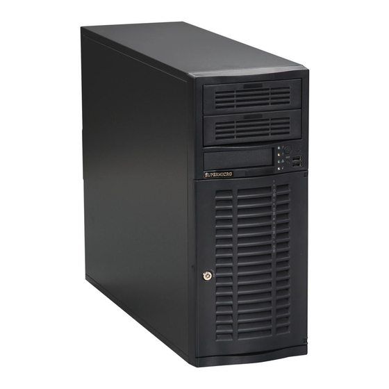
UPER ORKSTATION 7036A-T Manual Front Control Panel The front control panel must be connected to the JF1 connector on the motherboard to provide you with system status and alarm indications. A ribbon cable has bundled these wires together to simplify this connection. Connect the cable from JF1 on the motherboard (making sure the red wire plugs into pin 1) to the appropriate comn- nector on the front control panel PCB (printed circuit board). - Page 57 Chapter 6: Advanced Chassis Setup Figure 6-2. Chassis Front View 5.25" Drive Bays Floppy Drive Bay (optional) Main Power System Reset Front Side USB System LEDs SATA Active LED SATA Drive Confi guration Drive IDs are marked on the Front Bezel Lock front bezel.
-
Page 58: System Fans
UPER ORKSTATION 7036A-T Manual System Fans A 9-cm chassis cooling fan housed in a fan duct is located just below the peripheral drive bays to provide cool air intake for the system. A 12-cm exhaust fan in the power supply pulls the cool air through the system and expels the hot air. Fan Failure Under normal operation, the chassis fan and the power supply fan both run continu- ously. -
Page 59: Installing A New Fan
Chapter 6: Advanced Chassis Setup Installing a new fan Replace the failed fan with an identical one (available from Supermicro). After the new fan has been installed into the fan duct, reassemble the fan duct and perform the removal procedure in reverse to install the entire fan duct assembly back into the chassis. -
Page 60: Drive Bay Installation
UPER ORKSTATION 7036A-T Manual Drive Bay Installation A bezel covers the front of the chassis but does not need to be removed to access the drives. If you wish to remove the bezel piece, push on the three tabs on the inside left side lip of the front chassis cover. - Page 61 Chapter 6: Advanced Chassis Setup Figure 6-4. Removing a SATA Drive Carrier...
-
Page 62: Installing Components In The 5.25" Drive Bays
UPER ORKSTATION 7036A-T Manual Installing Components in the 5.25" Drive Bays The 7036A-T has two 5.25" drive bays above the SATA drive bays. Components such as a fl oppy drive, IDE hard drives or CD-ROM drives can be installed in these 5.25"... -
Page 63: Power Supply
Chapter 6: Advanced Chassis Setup Figure 6-5. Adding a Component Without a Drive Carrier Power Supply The 7036A-T has a single 665W high-effi ciency power supply that features noise- suppression technology for silent operation. The power supply has the capability to automatically sense and operate with an input voltage of 100 or 240V AC. - Page 64 UPER ORKSTATION 7036A-T Manual Notes 6-10...
-
Page 65: Chapter 7 Bios
Chapter 7: BIOS Chapter 7 BIOS Introduction This chapter describes the AMI BIOS Setup Utility for the X8DAL-i. The AMI ROM BIOS is stored in a Flash EEPROM and can be easily updated. This chapter de- scribes the basic navigation of the AMI BIOS Setup Utility setup screens. Starting BIOS Setup Utility To enter the AMI BIOS Setup Utility screens, press the <Delete>... -
Page 66: Starting The Setup Utility
UPER ORKSTATION 7036A-T User's Manual Starting the Setup Utility Normally, the only visible Power-On Self-Test (POST) routine is the memory test. As the memory is being tested, press the <Delete> key to enter the main menu of the AMI BIOS Setup Utility. From the main menu, you can access the other setup screens. - Page 67 Chapter 7: BIOS • Build Date : This item displays the date when this BIOS was completed. Processor The AMI BIOS will automatically display the status of the processor used in your system: • CPU Type : This item displays the type of CPU used in the motherboard. •...
-
Page 68: Advanced Setup Confi Gurations
UPER ORKSTATION 7036A-T User's Manual Advanced Setup Confi gurations Use the arrow keys to select Boot Setup and hit <Enter> to access the submenu items: BIOS SETUP UTILTY Main Advanced Security Boot Exit Advanced Settings Configure BOOT Features. BOOT Feature Processor &... -
Page 69: Processor And Clock Options
Chapter 7: BIOS Hit 'Del' Message Display This feature displays "Press DEL to run Setup" during POST. The options are Enabled and Disabled. Watch Dog Function If enabled, the Watch Dog Timer will allow the system to reboot when it is inactive for more than 5 minutes. - Page 70 UPER ORKSTATION 7036A-T User's Manual Hardware Prefetcher (Available when supported by the CPU) If set to Enabled, the hardware pre fetcher will pre fetch streams of data and instruc- tions from the main memory to the L2 cache in the forward or backward manner to improve CPU performance.
- Page 71 Chapter 7: BIOS C1E Support Select Enabled to use the feature of Enhanced Halt State. C1E signifi cantly reduces the CPU's power consumption by reducing the CPU's clock cycle and voltage during a "Halt State." The options are Disabled and Enabled. Intel®...
-
Page 72: Advanced Chipset Control
UPER ORKSTATION 7036A-T User's Manual Advanced Chipset Control The items included in the Advanced Settings submenu are listed below: QPI & IMC Confi guration QPI Links Speed This feature selects QPI's data transfer speed. The options are Slow-mode, and Full Speed. QPI Frequency This selects the desired QPI frequency. - Page 73 Chapter 7: BIOS Throttling - Closed Loop / Throttling - Open Loop Throttling improves reliability and reduces power in the processor by automatic voltage control during processor idle states. Available options are Disabled and Enabled. If Enabled, the following items will appear: Hysteresis Temperature (Closed Loop only) Temperature Hysteresis is the temperature lag (in degrees Celsius) after the set DIMM temperature threshold is reached before Closed Loop Throttling...
- Page 74 UPER ORKSTATION 7036A-T User's Manual Intel VT-d Select Enabled to enable Intel's Virtualization Technology support for Direct I/O VT-d by reporting the I/O device assignments to VMM through the DMAR ACPI Tables. This feature offers fully-protected I/O resource-sharing across the Intel platforms, providing the user with greater reliability, security and availability in networking and data-sharing.
- Page 75 Chapter 7: BIOS USB 2.0 Controller Select Enabled to activate the onboard USB2.0 controller. The options are En- abled and Disabled. Legacy USB Support Select Enabled to use Legacy USB devices. If this item is set to Auto, Legacy USB support will be automatically enabled if a legacy USB device is installed on the motherboard, and vise versa.
- Page 76 UPER ORKSTATION 7036A-T User's Manual Primary IDE Master/Slave, Secondary IDE Master/Slave, Third IDE Master, and Fourth IDE Master These settings allow the user to set the parameters of Primary IDE Master/Slave, Secondary IDE Master/Slave, Third and Fourth IDE Master slots. Hit <Enter> to activate the following submenu screen for detailed options of these items.
- Page 77 Chapter 7: BIOS Select 4 to allow the AMI BIOS to use PIO mode 4. It has a data transfer band- width of 32-Bits. Select Enabled to enable 32-Bit data transfer. DMA Mode Select Auto to allow the BIOS to automatically detect IDE DMA mode when the IDE disk drive support cannot be determined.
- Page 78 UPER ORKSTATION 7036A-T User's Manual the S.M.A.R.T. Select Enabled to allow the AMI BIOS to use the S.M.A.R.T. to support hard drive disk. The options are Disabled, Enabled, and Auto. 32Bit Data Transfer Select Enable to enable the function of 32-bit IDE data transfer. The options are Enabled and Disabled.
- Page 79 Chapter 7: BIOS Load Onboard LAN1 Option ROM/Load Onboard LAN2 Option ROM Select Enabled to enable the onboard LAN1 or LAN2 Option ROM. This is to boot computer using a network interface. The options are Enabled and Disabled. Load Onboard SAS Option ROM Select Enabled to enable the onboard SAS Option ROM.
-
Page 80: Hardware Health Monitor
UPER ORKSTATION 7036A-T User's Manual Serial Port Mode This feature allows the user to set the serial port mode for Console Redirection. The options are 115200 8, n 1; 57600 8, n, 1; 38400 8, n, 1; 19200 8, n, 1; and 9600 8, n, 1. - Page 81 Chapter 7: BIOS avoid possible system overheating, please be sure to provide adequate airfl ow to your system. The options are: • The Early Alarm: Select this setting if you want the CPU overheat alarm (includ- ing the LED and the buzzer) to be triggered as soon as the CPU temperature reaches the CPU overheat threshold as predefi...
- Page 82 UPER ORKSTATION 7036A-T User's Manual Notes: The CPU thermal technology that reports absolute temperatures (Celsius/Fahr- enheit) has been upgraded to a more advanced feature by Intel in its newer processors. The basic concept is each CPU is embedded by unique temperature information that the motherboard can read.
- Page 83 Chapter 7: BIOS High Performance Event Timer Select Enabled to activate the High Performance Event Timer (HPET) that produces periodic interrupts at a much higher frequency than a Real-time Clock (RTC) does in synchronizing multimedia streams, providing smooth playback and reducing the de- pendency on other timestamp calculation devices, such as an x86 RDTSC Instruc- tion embedded in the CPU.
-
Page 84: Security Settings
UPER ORKSTATION 7036A-T User's Manual Event Log Confi guration View Event Log Use this option to view the System Event Log. Mark all events as read This option marks all events as read. The options are OK and Cancel. Clear event log This option clears the Event Log memory of all messages. -
Page 85: Boot Confi Guration
Chapter 7: BIOS Change Supervisor Password Select this feature and press <Enter> to access the submenu, and then type in a new Supervisor Password. User Access Level (Available when Supervisor Password is set as above) Available options are Full Access: grants full User read and write access to the Setup Utility, View Only: allows access to the Setup Utility but the fi... - Page 86 UPER ORKSTATION 7036A-T User's Manual Boot Device Priority This feature allows the user to specify the sequence of priority for the Boot Device. The settings are 1st boot device, 2nd boot device, 3rd boot device, 4th boot device, 5th boot device and Disabled. •...
-
Page 87: Exit Options
Chapter 7: BIOS Exit Options Select the Exit tab from the AMI BIOS Setup Utility screen to enter the Exit BIOS Setup screen. BIOS SETUP UTILTY Main Advanced Security Boot Exit Boot Settings Exit system setup after saving the Save Changes and Exit changes. -
Page 88: Bios Recovery
UPER ORKSTATION 7036A-T User's Manual BIOS Recovery Warning! Do not upgrade the BIOS unless your system has a BIOS-related issue. Flashing the wrong BIOS can cause irreparable damage to the system. In no event shall Supermicro be liable for direct, indirect, special, incidental, or consequential damages arising from a BIOS update. -
Page 89: Boot Sector Recovery From An Ide Cd-Rom
Chapter 7: BIOS Boot Sector Recovery from an IDE CD-ROM This process is almost identical to the process of Boot Sector Recovery from a USB device, except that the BIOS image fi le is loaded from a CD-ROM. Use a CD-R or CD-RW drive to burn a CD with the BIOS image fi... - Page 90 UPER ORKSTATION 7036A-T User's Manual 4. Power on your system and click the <Connect> button in the Hyper Terminal. The terminal screen will display the following messages. Press <SpaceBar> to update BIOS. Confirm update BIOS? (y/n) y Begin remote BIOS flash? (y/n) y Starting remote flash.
- Page 91 Chapter 7: BIOS Once the ROM fi le extraction is completed, the message: "New BIOS re- ceived OK" will display. 8. Once remote BIOS fl ash is completed, the system will reboot. Note: AMIBIOS Serial Flash will work with any terminal communications program that supports VT-100 and XModem protocols, including protocols designed for GNU/LINUX &...
- Page 92 UPER ORKSTATION 7036A-T User's Manual Notes 7-28...
-
Page 93: Appendix A Bios Error Beep Codes
Appendix A: BIOS Error Beep Codes Appendix A BIOS Error Beep Codes During the POST (Power-On Self-Test) routines, which are performed each time the system is powered on, errors may occur. Non-fatal errors are those which, in most cases, allow the system to continue the boot-up process. - Page 94 UPER ORKSTATION 7036A-T User's Manual Notes...
-
Page 95: Appendix B Installing Windows
Appendix B: Installing Windows Appendix B Installing Windows After all hardware components have been installed, you must fi rst confi gure Intel South Bridge RAID Settings before you install the Windows OS and other software drivers. To confi gure RAID settings, please refer to RAID Confi guration User Guides posted on our website at www.supermicro.com/support/manuals. - Page 96 UPER ORKSTATION 7036A-T User's Manual B-2 Installing the Windows OS to a Non-RAID System Insert Microsoft's Windows XP/Windows 2003/Windows 2008/Windows Vista Setup CD in the CD-ROM drive, and the system will start booting up from CD. Continue with the OS installation. The Windows OS Setup screen will display. From the Windows OS Setup screen, press the <Enter>...
-
Page 97: Appendix C System Specifi Cations
Appendix C: System Specifi cations Appendix C System Specifi cations Processors Two Intel 5500 Series (LGA 1366) processors Note: Please refer to our web site for a complete listing of supported processors. Chipset Intel 5500 + ICH10R BIOS 16 MB AMI® SPI Flash ROM Memory Capacity Six DIMM sockets supporting up to 24 GB of ECC or unbuffered non-ECC DDR3-1333/1066/800 SDRAM... - Page 98 UPER ORKSTATION 7036A-T User's Manual Weight Gross (Bare Bone): 43 lbs. (19.5 kg.) System Cooling Six (6) paired sets of 4-cm counter-rotating cooling fans (fan speed controlled by BIOS setting) System Input Requirements AC Input Voltage: 100-240 VAC Rated Input Current: 10A (100V) to 5A (240V) Rated Input Frequency: 50/60 Hz Power Supply Rated Output Power: 665W (Part# PWS-665-PQ)
- Page 99 Appendix C: System Specifi cations Notes...
- Page 100 UPER ORKSTATION 7036A-T User's Manual (continued from front) The products sold by Supermicro are not intended for and will not be used in life support systems, medical equipment, nuclear facilities or systems, aircraft, aircraft devices, aircraft/emergency com- munication devices or other critical systems whose failure to perform be reasonably expected to result in signifi...
Need help?
Do you have a question about the SuperWorkstation 7036A-T and is the answer not in the manual?
Questions and answers