
Subscribe to Our Youtube Channel
Related Manuals for Supero SUPERSERVER 7047R-3RF4+


Summary of Contents for Supero SUPERSERVER 7047R-3RF4+
- Page 1 Niveus 5215s High Density for HPC Clusters Technical Guide Rev. 1.0 PENGUIN COMPUTING www.penguincomputing.com | 1-888-PENGUIN (736-4846) | twitter:@PenguinHPC...
- Page 2 UPER ® UPER ERVER 7047R-3RF4+ USER’S MANUAL...
- Page 3 This product, including software and docu- mentation, is the property of Supermicro and/or its licensors, and is supplied only under a license. Any use or reproduction of this product is not allowed, except as expressly permitted by the terms of said license.
-
Page 4: About This Manual
Preface Preface About This Manual This manual is written for professional system integrators and PC technicians. It provides information for the installation and use of the SuperServer 7047R-3RF4+. Installation and maintainance should be performed by experienced technicians only. The SuperServer 7047R-3RF4+ is a high-end server based on the SC745TQ- 920B 4U tower/rackmountable chassis and the X9DR3-LN4F+ dual processor serverboard. - Page 5 UPER ERVER 7047R-3RF4+ User's Manual Chapter 5: Advanced Serverboard Setup Chapter 5 provides detailed information on the X9DR3-LN4F+ serverboard, includ- ing the locations and functions of connections, headers and jumpers. Refer to this chapter when adding or removing processors or main memory and when reconfi g- uring the serverboard.
- Page 6 Preface Notes...
-
Page 7: Table Of Contents
Rear I/O Ports ....................1-3 Server Chassis Features ................1-3 System Power ....................1-3 Front Control Panel ..................1-3 Cooling System ....................1-3 Contacting Supermicro ..................1-5 Chapter 2 Server Installation Overview ......................2-1 Unpacking the System ..................2-1 Preparing for Setup ..................2-1 Choosing a Setup Location ................ - Page 8 Table of Contents Reset ....................... 3-1 Control Panel LEDs ..................3-2 Power ......................3-2 HDD ......................... 3-2 NIC1 ........................ 3-2 NIC2 ........................ 3-2 Information LED ....................3-3 Power Fail ....................... 3-3 Drive Carrier LEDs ..................3-3 Chapter 4 System Safety Electrical Safety Precautions ................
- Page 9 UPER ERVER 7047R-3RF4+ User's Manual 5-13 Installing Software ..................5-29 SuperDoctor III ....................5-30 Chapter 6 Advanced Chassis Setup Static-Sensitive Devices .................. 6-1 Precautions ..................... 6-1 Front Control Panel ..................6-3 System Fans ....................6-4 Fan Failure ...................... 6-4 Drive Bay Installation ..................6-6 SAS/SATA Hard Drives ...................
-
Page 10: Chapter 1 Introduction
SC745TQ-R920B 4U/tower chassis and the X9DR3-LN4F+ dual processor serverboard. Please refer to our web site for information on operating systems that have been certifi ed for use with the system (www.supermicro.com). In addition to the serverboard and chassis, various hardware components have been included with the 7047R-3RF4+, as listed below: •... -
Page 11: Serverboard Features
The X9DR3-LN4F+ supports single or dual Intel® Xeon E5-2600 Series processors. Please refer to the serverboard description pages on our web site for a complete listing of supported processors (www.supermicro.com). Memory The X9DR3-LN4F+ has 24 DIMM slots that can support up to 768 GB of ECC reg- istered DDR3-1333/1066/800 SDRAM. -
Page 12: Rear I/O Ports
Chapter 1: Introduction Rear I/O Ports The color-coded I/O ports include one COM port, a VGA port, four USB 2.0 ports (additional USB headers are included on the serverboard) and four gigabit Ethernet ports. A dedicated IPMI LAN port is also included. Server Chassis Features The following is a general outline of the main features of the SC745TQ-R920B server chassis. -
Page 13: System Block Diagram
UPER ERVER 7047R-3RF4+ User's Manual Figure 1-1. Intel C600 Chipset: System Block Diagram Note: This is a general block diagram. Please see Chapter 5 for details. CPU REAR Socket 01 U7C1 PROCESSOR U7C1 U6H1 CPU FRONT U6H1 Socket 00 PROCESSOR SYSTEM BIOS SATA... -
Page 14: Contacting Supermicro
Super Micro Computer, Inc. 980 Rock Ave. San Jose, CA 95131 U.S.A. Tel: +1 (408) 503-8000 Fax: +1 (408) 503-8008 Email: marketing@supermicro.com (General Information) support@supermicro.com (Technical Support) Web Site: www.supermicro.com Europe Address: Super Micro Computer B.V. Het Sterrenbeeld 28, 5215 ML... - Page 15 UPER ERVER 7047R-3RF4+ User's Manual Notes...
-
Page 16: Chapter 2 Server Installation
Chapter 2: Server Installation Chapter 2 Server Installation Overview This chapter provides a quick setup checklist to get your SuperServer 7047R-3RF4+ up and running. Following these steps in the order given should enable you to have the system operational within a minimum amount of time. This quick setup assumes that your system has come to you with the processors and memory preinstalled. -
Page 17: Choosing A Setup Location
UPER ERVER 7047R-3RF4+ User's Manual Choosing a Setup Location • Leave enough clearance in front of the rack to enable you to open the front door completely (~25 inches) and approximately 30 inches of clearance in the back of the rack to allow for suffi cient airfl ow and ease in servicing. •... -
Page 18: Rack Mounting Considerations
Chapter 2: Server Installation • Allow the hot plug SATA drives and power supply modules to cool before touch- ing them. • Always keep the rack's front door and all panels and components on the servers closed when not servicing to maintain proper cooling. Rack Mounting Considerations Ambient Operating Temperature If installed in a closed or multi-unit rack assembly, the ambient operating tempera-... -
Page 19: Installing The System Into A Rack
UPER ERVER 7047R-3RF4+ User's Manual Installing the System into a Rack This section provides information on installing the system into a rack unit. Rack installation requires the use of the optional rackmount kit. If the system has already been mounted into a rack or if you are using it as a tower, you can skip ahead to Sections 2-5 and 2-6. -
Page 20: Installing The Chassis Rails
Chapter 2: Server Installation Installing the Chassis Rails You will need to remove the top cover and the feet to add rack rails to the chassis. First, remove the top and right covers (top and left covers when standing as a tower chassis) by fi... -
Page 21: Installing The Rack Rails
UPER ERVER 7047R-3RF4+ User's Manual Figure 2-3. Installing the Rails to the Chassis Installing the Rack Rails Determine where you want to place the SuperServer 7047R-3RF4+ in the rack. (See Rack and Server Precautions in Section 2-3.) Position the fi xed rack rail/sliding rail guide assemblies at the desired location in the rack, keeping the sliding rail guide facing the inside of the rack. -
Page 22: Installing The Server Into The Rack
Chapter 2: Server Installation Installing the Server into the Rack You should now have rails attached to both the chassis and the rack unit. The next step is to install the server into the rack. You should have two brackets in the rack mount kit. - Page 23 UPER ERVER 7047R-3RF4+ User's Manual Notes...
-
Page 24: Chapter 3 System Interface
Chapter 3: System Interface Chapter 3 System Interface Overview The control panel on the 7047R-3RF4+ has several LEDs and two buttons. There are also two LEDs on each hard drive carrier. These LEDs keep you constantly informed of the overall status of the system and the activity and health of specifi c components. -
Page 25: Control Panel Leds
UPER ERVER 7047R-3RF4+ User's Manual Control Panel LEDs The control panel located on the front of the SC745 chassis has six LEDs that provide you with critical information related to different parts of the system. This section explains what each LED indicates when illuminated and any corrective ac- tion you may need to take. -
Page 26: Information Led
Chapter 3: System Interface Information LED This LED will be solid blue when the UID function has been activated. When this LED fl ashes red, it indicates a fan failure. When red continuously it indicates an overheat condition, which may be caused by cables obstructing the airfl ow in the system or the ambient room temperature being too warm. - Page 27 UPER ERVER 7047R-3RF4+ User's Manual Notes...
-
Page 28: Chapter 4 System Safety
Chapter 4: System Safety Chapter 4 System Safety Electrical Safety Precautions Basic electrical safety precautions should be followed to protect yourself from harm and the SuperServer 7047R-3RF4+ from damage: • Be aware of the locations of the power on/off switch on the chassis as well as the room's emergency power-off switch, disconnection switch or electrical outlet. -
Page 29: General Safety Precautions
UPER ERVER 7047R-3RF4+ User's Manual • This product may be connected to an IT power system. In all cases, make sure that the unit is also reliably connected to Earth (ground). • Serverboard Battery: CAUTION - There is a danger of explosion if the onboard battery is installed upside down, which will reverse its polarites (see Figure 4-1). -
Page 30: Esd Precautions
Chapter 4: System Safety • Remove any jewelry or metal objects from your body, which are excellent metal conductors that can create short circuits and harm you if they come into contact with printed circuit boards or areas where power is present. •... -
Page 31: Operating Precautions
UPER ERVER 7047R-3RF4+ User's Manual Operating Precautions Care must be taken to assure that the chassis cover is in place when the 7047R- 3RF4+ is operating to assure proper cooling. Out of warranty damage to the system can occur if this practice is not strictly followed. Figure 4-1. -
Page 32: Chapter 5 Advanced Serverboard Setup
Chapter 5: Advanced Serverboard Setup Chapter 5 Advanced Serverboard Setup This chapter covers the steps required to install the X9DR3-LN4F+ serverboard into the chassis, connect the data and power cables and install add-on cards. All serverboard jumpers and connections are also described. A layout and quick refer- ence chart are included in this chapter for your reference. -
Page 33: Unpacking
UPER ERVER 7047R-3RF4+ User's Manual Unpacking The serverboard is shipped in antistatic packaging to avoid electrical static dis- charge. When unpacking the board, make sure the person handling it is static protected. Serverboard Installation This section explains the fi rst step of physically mounting the X9DR3-LN4F+ into the SC745TQ-R920B chassis. -
Page 34: Connecting Cables
Chapter 5: Advanced Serverboard Setup Connecting Cables Now that the serverboard is installed, the next step is to connect the cables to the board. These include the data cables for the peripherals and control panel and the power cables. Connecting Data Cables The cables used to transfer data from the peripheral devices have been carefully routed to prevent them from blocking the fl... -
Page 35: Rear I/O Ports
UPER ERVER 7047R-3RF4+ User's Manual Figure 5-1. Control Panel Header Pins Ground x (Key) x (Key) Power On LED 3.3V HDD LED ID/UID/SW/3.3V Stby NIC1 Link LED NIC1 Activity LED NIC2 Link LED NIC2 Activity LED OH/Fan Fail LED Red + (Blue Cathode Power Fail LED 3.3V Ground... -
Page 36: Installing The Processor And Heatsink
CPU socket cap is in place and none of the socket pins are bent; otherwise, contact your retailer immediately. • Refer to the Supermicro web site for updates on CPU support. Installing an LGA2011 Processor Press down on the lever labeled 'Close 1st' 1. - Page 37 UPER ERVER 7047R-3RF4+ User's Manual 3. With the lever labeled 'Close 1st' fully retracted, gently push down on the 'Open 1st' lever to open the load plate. Lift the load plate to open it completely. Gently push 4. Using your thumb and the index down to pop the load plate fi...
- Page 38 Chapter 5: Advanced Serverboard Setup Warning: You can only install the CPU to the socket in one direction. Make sure that the CPU is properly inserted into the socket before closing the load plate. If it doesn't close properly, do not force it as it may damage your CPU.
-
Page 39: Installing A Passive Cpu Heatsink
UPER ERVER 7047R-3RF4+ User's Manual Installing a Passive CPU Heatsink 1. Do not apply any thermal grease to the heatsink or the CPU die -- the re- quired amount has already been applied to the heatsink. 2. Place the heatsink on top of the CPU so that the four mounting holes are aligned with those on the Motherboard's and the Heatsink Bracket under- neath. -
Page 40: Removing The Heatsink
Chapter 5: Advanced Serverboard Setup Removing the Heatsink Warning: We do not recommend that the CPU or the heatsink be removed. However, if you do need to uninstall the heatsink, please follow the instruc- tions below to uninstall the heatsink to prevent damage done to the CPU or the CPU socket. -
Page 41: Installing Memory
UPER ERVER 7047R-3RF4+ User's Manual Installing Memory CAUTION! Exercise extreme care when installing or removing DIMM modules to prevent any possible damage. Memory Support The X9DR3-LN4F+ supports up to 768 GB of ECC registered DDR3- 1600/1333/1066/800 SDRAM. Both 1.5V and 1.35V DIMMs are supported. For best performance, install pairs of memory modules of the same type and speed. - Page 42 Chapter 5: Advanced Serverboard Setup DIMM Module Population Table Follow the table below when installing memory. Processors and their Corresponding Memory Slots CPU# Corresponding Memory Slot CPU 1 (P1-) CPU2 (P2-) Processor and Memory Module Population Number of CPU and Memory Population Confi guration Table CPUs+DIMMs (For memory to work properly, please install DIMMs according to this table) 1 CPU &...
-
Page 43: Adding Pci Add-On Cards
UPER ERVER 7047R-3RF4+ User's Manual Adding PCI Add-On Cards The 7047R-3RF4+ can accommodate up to six full-length, low-profi le PCI add-on cards (four x16 cards, one x8 card and one x4 card in a x8 slot). Installing an Add-on Card 1. -
Page 44: Serverboard Details
Chapter 5: Advanced Serverboard Setup Serverboard Details Figure 5-4. X9DR3-LN4F+ Layout FAN5 P2 DIMMG1 JPI2C1 JPW3 P2 DIMMG2 JPW1 JPW2 P1 DIMMA1 P2 DIMMG3 P2 DIMMH1 P1 DIMMA2 P1 DIMMA3 P2 DIMMH2 P2 DIMMH3 P1 DIMMB1 Alaways populate DIMMx1 first P1 DIMMB2 FAN6 P1 DIMMB3... -
Page 45: X9Dr3-Ln4F+ Quick Reference
UPER ERVER 7047R-3RF4+ User's Manual X9DR3-LN4F+ Quick Reference Jumper Description Default Setting JBT1 Clear CMOS See Section 5-10 C1/JI SMB to PCI-E Slots Pins 2-3 (Normal) XDP (Extended Debug Port) Open (Disabled) JPB1 BMC Enable/Disbable Pins 1-2 (Enabled) JPG1 VGA Enable/Disable Pins 1-2 (Enabled) JPL1 LAN1/LAN2 Enable/Disable... - Page 46 Chapter 5: Advanced Serverboard Setup JPW2/JPW3 12V 8-Pin Power Connectors JRK1 RAIDKey JSD1 SATA DOM (Device On Module) Power Connector JSTBY1 Standby Header JTPM1 TPM (Trusted Platform Module)/Port 80 LAN1/3, LAN2/4 G-bit Ethernet Ports 1/3, 2/4 (IPMI) LAN IPMI Dedicated LAN SAS 0~3, 4~7 Serial Attached SCSI Ports 0~3, 4~7 Onboard Buzzer (Internal Speaker)
-
Page 47: Connector Defi Nitions
UPER ERVER 7047R-3RF4+ User's Manual Connector Defi nitions ATX Power 24-pin Connector Pin Defi nitions Pin# Defi nition Pin # Defi nition Power Connectors +3.3V +3.3V -12V +3.3V A 24-pin main power supply connec- tor (JPW1) and two 8-pin CPU power PS_ON connectors (JPW2/3) must be con- nected to the power supply. - Page 48 Chapter 5: Advanced Serverboard Setup Power Fail LED PWR Fail LED The Power Fail LED connection is Pin Defi nitions (JF1) located on pins 5 and 6 of JF1. See Pin# Defi nition p. 5-4 and the table on the right for pin defi...
- Page 49 UPER ERVER 7047R-3RF4+ User's Manual Power On LED Power LED Pin Defi nitions (JF1) The Power On LED connector is lo- Pin# Defi nition cated on pins 15 and 16 of JF1 (use 5V Stby JLED for a 3-pin connector). This Control connection is used to provide LED indication of power being supplied to...
- Page 50 Chapter 5: Advanced Serverboard Setup Chassis Intrusion Chassis Intrusion Pin Defi nitions The Chassis Intrusion header is des- Pin# Defi nition ignated JL1. Attach a chassis intrusion Intrusion Input cable from the chassis to inform you of Ground a chassis intrusion when the chassis is opened Ethernet Ports Four Ethernet ports are located on the...
- Page 51 UPER ERVER 7047R-3RF4+ User's Manual Type A USB Ports Back Panel USB (USB9) (USB 0/1/2/3) Pin# Defi nition Pin# Defi nitions Universal Serial Bus (USB) Data- There are four Universal Serial Bus Data+ ports located on the I/O panel. In addi- Ground Ground tion, there is one Type A port and two...
- Page 52 Chapter 5: Advanced Serverboard Setup IPMB IPMB Header Pin Defi nitions A System Management Bus header Pin# Defi nition for IPMI 2.0 is located at IPMB. Con- Data nect the appropriate cable here to Ground use the IPMB I C connection on your Clock system.
- Page 53 Note: UID can also be triggered via IPMI. For more information on IPMI, please refer to the IPMI User's Guide posted on our Website @http://www.supermicro.com. Power SMB (I C) Connector PWR SMB Pin Defi...
-
Page 54: 5-10 Jumper Settings
Chapter 5: Advanced Serverboard Setup 5-10 Jumper Settings Explanation of Jumpers To modify the operation of the serverboard, jumpers can be used Connector to choose between optional settings. Pins Jumpers create shorts between two pins to change the function of the con- nector. - Page 55 UPER ERVER 7047R-3RF4+ User's Manual LAN Enable/Disable LAN Enable Jumper Settings JPL1 enables or disables the LAN Jumper Setting Defi nition ports on the motherboard. See the Enabled (default) table on the right for jumper settings. Disabled The default setting is Enabled. C Bus to PCI-Exp.
- Page 56 Chapter 5: Advanced Serverboard Setup Manufacturer's Mode Jumper JPME2 allows the user to ME Mode Select Jumper Settings flash the system firmware from a Jumper Setting Defi nition host server in order to modify system Pins 1-2 Manufacture's Mode settings. Close this jumper to bypass Pins 2-3 Normal (Default) SPI fl...
- Page 57 UPER ERVER 7047R-3RF4+ User's Manual Watch Dog Enable/Disable Jumper JWD controls the Watch Dog function. Watch Dog is a sys- tem monitor that can reboot the system when a software application hangs. Jumping pins 1-2 will cause Watch Dog WD to reset the system if an appli- Jumper Settings cation hangs.
-
Page 58: 5-11 Onboard Indicators
Chapter 5: Advanced Serverboard Setup 5-11 Onboard Indicators LAN LEDs The Ethernet ports (located beside the JLAN1/2 LED VGA port) have two LEDs. On each (Connection Speed Indicator) port, the yellow LED fl ashes to indi- LED Color Defi nition cate activity while the other LED may NC or 10 Mbps be green, amber or off to indicate the... -
Page 59: 5-12 Sata And Sas Ports
UPER ERVER 7047R-3RF4+ User's Manual 5-12 SATA and SAS Ports Serial ATA Ports SATA Port There are six Serial ATA Ports (I- Pin Defi nitions SATA0~I-SATA 5) located on the Pin# Defi nition Defi nition motherboard, including four SATA2 Ground ports and two SATA3 ports. -
Page 60: 5-13 Installing Software
5-13 Installing Software After the hardware has been installed, you should fi rst install the operating system and then the drivers. The necessary drivers are all included on the Supermicro CDs that came packaged with your motherboard. Driver/Tool Installation Display Screen Note: Click the icons showing a hand writing on paper to view the readme fi... - Page 61 UPER ERVER 7047R-3RF4+ User's Manual SuperDoctor III ® The SuperDoctor III program is a Web base management tool that supports remote management capability. It includes Remote and Local Management tools. The local management is called SD III Client. The SuperDoctor III program included on the CD-ROM that came with your motherboard allows you to monitor the environment and operations of your system.
-
Page 62: Superdoctor Iii
Chapter 5: Advanced Serverboard Setup Supero Doctor III Interface Display Screen (Remote Control) Note: The SuperDoctor III program and User's Manual can be downloaded from the Supermicro web site at http://www.supermicro.com/products/accessories/software/ SuperDoctorIII.cfm. For Linux, we recommend using SuperDoctor II. 5-31... - Page 63 UPER ERVER 7047R-3RF4+ User's Manual Notes 5-32...
-
Page 64: Chapter 6 Advanced Chassis Setup
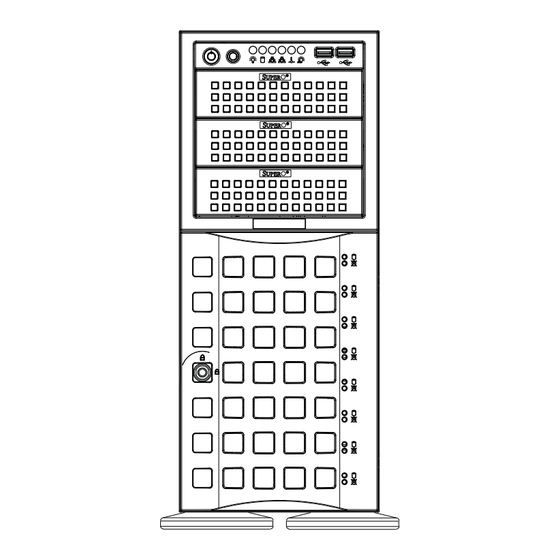
Chapter 6: Advanced Chassis Setup Chapter 6 Advanced Chassis Setup This chapter covers the steps required to install components and perform simple maintenance on the SC745TQ-R920B chassis. Following the component installation steps in the order given will eliminate most common problems. If some steps are unnecessary, skip ahead to the step that follows. - Page 65 UPER ERVER 7047R-3RF4+ User's Manual Figure 6-1. Chassis Front View Main Power System Reset USB Ports 5.25" Drive Bays (2) 8 Hard Drive Bays (behind locking bezel)
-
Page 66: Front Control Panel
Chapter 6: Advanced Chassis Setup Front Control Panel The front control panel must be connected to the JF1 connector on the serverboard to provide you with system status and alarm indications. A ribbon cable has bundled these wires together to simplify this connection. Connect the cable from JF1 on the serverboard (making sure the red wire plugs into pin 1) to the appropriate comnnec- tor on the front control panel PCB (printed circuit board). -
Page 67: System Fans
UPER ERVER 7047R-3RF4+ User's Manual System Fans Three 8-cm chassis cooling fans (located in the center of the chassis) provide cool- ing airfl ow while two 8-cm exhaust fans expel hot air from the chassis. The chassis is also fi tted with an air shroud to concentrate the fl ow of cooling air over the areas of highest generated heat. - Page 68 Chapter 6: Advanced Chassis Setup Removing the Air Shroud Under most circumstances you will not need to remove the air shroud to perform any service on the system. However, if you wish to temporarily remove it (the air shroud should always be in place when the system is operating), please follow this procedure.
-
Page 69: Drive Bay Installation
Regardless of how many drives are installed, all drive carriers must remain in the drive bays to promote proper airfl ow. Warning! Enterprise level hard disk drives are recommended for use in Supermicro chassis and servers. For information on recommended HDDs, visit the Supermicro Web site at http://www.supermicro.com/products/nfo/ storage.cfm Installing/Removing Hard Drives 1. -
Page 70: Sas/Sata Backplane
Chapter 6: Advanced Chassis Setup Figure 6-5. Removing a Drive Carrier Figure 6-6. Mounting a Drive in a Carrier Important! Use extreme caution when working around the SAS/SATA back- plane. Do not touch the backplane with any metal objects and make sure no cables touch the backplane or obstruct the airfl... -
Page 71: Storage Module
UPER ERVER 7047R-3RF4+ User's Manual Installing Components in the 5.25" Drive Bays The 7047R-3RF4+ has two 5.25" drive bays. DVD-ROM drives can be installed into these 5.25" drive bays. 1. First power down the system and then remove the top/left chassis cover to access the drive components. - Page 72 Chapter 6: Advanced Chassis Setup Figure 6-7. Rotating the Storage Module Storage Module Storage Module Release Lever...
-
Page 73: Power Supply
The PWR Fail LED will illuminate and remain on until the failed unit has been replaced. Replacement units can be ordered directly from Supermicro (see contact information in the Pref- ace). The hot-swap capability of the power supply modules allows you to replace the failed module without powering down the system. -
Page 74: Chapter 7 Bios
Chapter 7: BIOS Chapter 7 BIOS Introduction This chapter describes the AMI BIOS Setup utility for the X9DR3-LN4F+/X9DRi- LN4F+. It also provides the instructions on how to navigate the AMI BIOS Setup utility screens. The AMI ROM BIOS is stored in a Flash EEPROM and can be easily updated. -
Page 75: Starting The Setup Utility
UPER ERVER 7047R-3RF4+ User's Manual Note: For AMI UEFI BIOS Recovery, please refer to the UEFI BIOS Re- covery User Guide posted @http://www.supermicro.com/support/manuals/. Starting the Setup Utility Normally, the only visible Power-On Self-Test (POST) routine is the memory test. As the memory is being tested, press the <F2> key to enter the main menu of the AMI BIOS Setup utility. -
Page 76: Advanced Setup Confi Gurations
Chapter 7: BIOS System Time This item displays the system time in HH:MM:SS format (e.g. 15:32:52). Supermicro X9DRi-LN4+/X9DR3-LN4+ Version This item displays the SMC version of the BIOS ROM used in this system. Build Date This item displays the date that the BIOS Setup utility was built. - Page 77 UPER ERVER 7047R-3RF4+ User's Manual AddOn ROM Display Mode Use this item to set the display mode for the Option ROM. Select Keep Current to use the current AddOn ROM Display setting. Select Force BIOS to use the Option ROM display mode set by the system BIOS. The options are Force BIOS and Keep Current.
- Page 78 Chapter 7: BIOS CPU Confi guration This submenu displays the information of the CPU as detected by the BIOS. It also allows the user to confi guration CPU settings. Socket 1 CPU Information/Socket 2 CPU Information This submenu displays the following information regarding the CPUs installed in Socket 1/ Socket 2.
- Page 79 UPER ERVER 7047R-3RF4+ User's Manual Clock Spread Spectrum Select Enable to enable Clock Spectrum support, which will allow the BIOS to moni- tor and attempt to reduce the level of Electromagnetic Interference caused by the components whenever needed. The options are Disabled and Enabled. Hyper-threading Select Enabled to support Intel Hyper-threading Technology to enhance CPU per- formance.
- Page 80 Chapter 7: BIOS DCU IP Prefetcher Select Enabled for DCU (Data Cache Unit) IP Prefetcher support, which will prefetch IP addresses to improve network connectivity and system performance. The options are Enabled and Disabled. Intel® Virtualization Technology (Available when supported by the CPU) Select Enabled to support Intel Virtualization Technology, which will allow one platform to run multiple operating systems and applications in independent parti- tions, creating multiple "virtual"...
- Page 81 UPER ERVER 7047R-3RF4+ User's Manual CPU C3 Report (Available when Power Technology is set to Custom) Select Enabled to allow the BIOS to report the CPU C3 State (ACPI C2) to the operating system. During the CPU C3 State, the CPU clock generator is turned off.
-
Page 82: North Bridge
Chapter 7: BIOS Short Duration Power Limit This item displays the time period during which short duration power is main- tained. Chipset Confi guration North Bridge This feature allows the user to confi gure the settings for the Intel North Bridge. Integrated IO Confi... - Page 83 UPER ERVER 7047R-3RF4+ User's Manual CPU1 Slot3 PCI-E 3.0 x16 Link Speed This feature allows the user to set the PCI-Exp bus speed for the slot specifi ed above. The options are Gen1 (Generation 1), Gen2 and Gen3. CPU1 Slot1 PCI-E 3.0 x16 Link Speed This feature allows the user to set the PCI-Exp bus speed for the slot specifi...
- Page 84 Chapter 7: BIOS QPI Link Frequency Select Use this feature to select the desired QPI frequency. The options are Auto, 6.4 GT/s, 7.2 GT/s, and 8.0 GT/s. DIMM Confi guration This section displays the following DIMM information. Current Memory Mode This item displays the current memory mode.
- Page 85 UPER ERVER 7047R-3RF4+ User's Manual DDR Speed Use this feature to force a DDR3 memory module to run at a frequency other than what is specifi ed in the specifi cation. The options are Auto, Force DDR3- 800, Force DDR3-1066, Force DDR3-1333, Force DDR3-1600 and Force SPD. Channel Interleaving This feature selects from the different channel interleaving methods.
- Page 86 Chapter 7: BIOS South Bridge Confi guration This feature allows the user to confi gure the settings for the Intel PCH chip. PCH Information This feature displays the following PCH information. Name: This item displays the name of the PCH chip. Stepping: This item displays the status of the PCH stepping.
- Page 87 UPER ERVER 7047R-3RF4+ User's Manual SATA Mode Use this feature to confi gure SATA mode for a selected SATA port. The options are Disabled, IDE Mode, AHCI Mode and RAID Mode. The following are displayed depending on your selection: IDE Mode The following items are displayed when IDE Mode is selected: SATA (Serial-ATA) Controller 0~1 Use this feature to activate or deactivate the SATA controller, and set the...
- Page 88 Chapter 7: BIOS SCU (Storage Control Unit) Confi guration Storage Controller Unit Select Enabled to enable PCH SCU storage devices. The options are Disabled and Enabled. OnChip SCU Option ROM Select Enabled to support the onboard SCU Option ROM to boot up the system via a storage device.
- Page 89 UPER ERVER 7047R-3RF4+ User's Manual Maximum Read Request Select Auto to allow the system BIOS to automatically set the maximum Read Request size for a PCI-E device to enhance system performance. The options are Auto, 128 Bytes, 256 Bytes, 512 Bytes, 1024 Bytes, 2048 Bytes, and 4096 Bytes. ASPM Support This feature allows the user to set the Active State Power Management (ASPM) level for a PCI-E device.
- Page 90 Chapter 7: BIOS Super IO Confi guration Super IO Chip: This item displays the Super IO chip used in the motherboard. Serial Port 1 Confi guration Serial Port Select Enabled to enable a serial port specifi ed by the user. The options are En- abled and Disabled.
-
Page 91: Serial Port Console Redirection
UPER ERVER 7047R-3RF4+ User's Manual Serial Port Console Redirection • COM 1/COM 2 These two submenus allow the user to confi gure the following Console Redirection settings for a COM Port specifi ed by the user. Console Redirection Select Enabled to use a COM Port selected by the user for Console Redirection. The options are Enabled and Disabled. - Page 92 Chapter 7: BIOS Stop Bits A stop bit indicates the end of a serial data packet. Select 1 Stop Bit for standard serial data communication. Select 2 Stop Bits if slower devices are used. The options are 1 and 2. Flow Control This feature allows the user to set the fl...
- Page 93 UPER ERVER 7047R-3RF4+ User's Manual ACPI Setting Use this feature to confi gure Advanced Confi guration and Power Interface (ACPI) power management settings for your system. ACPI Sleep State Use this feature to select the ACPI State when the system is in sleep mode. Select S1 (CPU_Stop_Clock) to erase all CPU caches and stop executing instructions.
-
Page 94: Tpm Enable Status
Chapter 7: BIOS Pending Operation: This item displays the status of a pending operation. Current Status Information: This item displays the information regarding the current TPM status. TPM Enable Status This item displays the status of TPM Support to indicate if TPM is currently enabled or disabled. - Page 95 UPER ERVER 7047R-3RF4+ User's Manual Intel ME Subsystem Confi guration This feature displays the following ME Subsystem Confi guration settings. • ME BIOS Interface Version • ME Version iSCSI Confi guration: This item displays iSCSI confi guration information: iSCSI Initiator Name: This item displays the name of the iSCSI Initiator, which is a unique name used in the world.
-
Page 96: Event Logs
Chapter 7: BIOS Event Logs Use this feature to confi gure Event Log settings. Change SMBIOS Event Log Settings This feature allows the user to confi gure SMBIOS Event settings. Enabling/Disabling Options SMBIOS Event Log Select Enabled to enable SMBIOS (System Management BIOS) Event Logging during system boot. - Page 97 UPER ERVER 7047R-3RF4+ User's Manual Erasing Settings Erase Event Log Select Enabled to erase the SMBIOS (System Management BIOS) Event Log, which is completed before a event logging is initialized upon system reboot. The options are No and Yes. When Log is Full Select Erase Immediately to immediately erase SMBIOS error event logs that ex- ceed the limit when the SMBIOS event log is full.
-
Page 98: Ipmi
Chapter 7: BIOS IPMI Use this feature to confi gure Intelligent Platform Management Interface (IPMI) settings. IPMI Firmware Revision This item indicates the IPMI fi rmware revision used in your system. IPMI Status This item indicates the status of the IPMI fi rmware installed in your system. ... - Page 99 UPER ERVER 7047R-3RF4+ User's Manual When SEL is Full This feature allows the user to decide what the BIOS should do when the system event log is full. Select Erase Immediately to erase all events in the log when the system event log is full.
-
Page 100: Boot
Chapter 7: BIOS Gateway IP Address This item displays the Gateway IP address for this computer. This should be in decimal and in dotted quad form (i.e., 192.168.10.253). Boot This submenu allows the user to confi gure the following boot settings for the system. -
Page 101: Security
UPER ERVER 7047R-3RF4+ User's Manual Network Devices Boot Option #1 This item displays the fi rst boot device. Delete Boot Options Delete Boot Option This item allows the user to select a boot device to delete from the boot priority list. -
Page 102: Save & Exit
Chapter 7: BIOS Save & Exit This submenu allows the user to confi gure the Save and Exit settings for the system. Discard Changes and Exit Select this option to quit the BIOS Setup without making any permanent changes to the system confi guration, and reboot the computer. Select Discard Changes and Exit, and press <Enter>. - Page 103 UPER ERVER 7047R-3RF4+ User's Manual Discard Changes Select this feature and press <Enter> to discard all the changes and return to the BIOS setup. When the dialog box appears, asking you if you want to load previ- ous values, click Yes to load the values previous saved, or click No to keep the changes you've made so far.
-
Page 104: Appendix A Bios Error Beep Codes
Appendix A: BIOS Error Beep Codes Appendix A BIOS Error Beep Codes During the POST (Power-On Self-Test) routines, which are performed at each system boot, errors may occur. Non-fatal errors are those which, in most cases, allow the system to continue to boot. - Page 105 UPER ERVER 7047R-3RF4+ User's Manual Notes...
-
Page 106: Appendix B System Specifi Cations
Appendix B: System Specifi cations Appendix B System Specifi cations Processors Single or dual Intel® Xeon E5-2600 Series processors Note: Please refer to our web site for a complete listing of supported processors. Chipset Intel C600 chipset BIOS 32 Mb AMI® SPI Flash ROM Memory Capacity Twenty-four DIMM sockets supporting up to 768 GB of registered ECC DDR3- 1333/1066/800 SDRAM... - Page 107 UPER ERVER 7047R-3RF4+ User's Manual Weight Gross (Bare Bone): 70 lbs. (31.8 kg.) System Cooling Three (3) 8-cm system cooling fans Two (2) 8-cm rear exhaust fans One (1) air shroud System Input Requirements AC Input Voltage: 100 - 240V AC auto-range Rated Input Current: 13 - 4A max Rated Input Frequency: 50 to 60 Hz Power Supply...
- Page 108 Appendix B: System Specifi cations Notes...
- Page 109 ERVER 7047R-3RF4+ User's Manual (continued from front) The products sold by Supermicro are not intended for and will not be used in life support systems, medical equipment, nuclear facilities or systems, aircraft, aircraft devices, aircraft/emergency com- munication devices or other critical systems whose failure to perform be reasonably expected to result in signifi...
Need help?
Do you have a question about the SUPERSERVER 7047R-3RF4+ and is the answer not in the manual?
Questions and answers