Minicom CAT5 User Manual
Smart cat5 switch 8 and 16 port
Hide thumbs
Also See for CAT5:
- User manual (45 pages) ,
- Quick installation manual (10 pages) ,
- Quick installation manual (9 pages)
Table of Contents
Advertisement
Quick Links
Download this manual
See also:
User Manual
International HQ
Jerusalem, Israel
Tel: + 972 2 535 9666
minicom@minicom.com
Smart CAT5 Switch
8 and 16 Port
User Guide
w w w . m i n i c o m . c o m
North America
Linden, NJ, USA
Tel: + 1 908 486 2100
info.usa@minicom.com
Technical support -
support@minicom.com
Europe
Dübendorf, Switzerland
Tel: + 41 44 823 8000
info.europe@minicom.com
5UM20110 V1.7 4/07
Advertisement
Table of Contents

Related Manuals for Minicom CAT5


Summary of Contents for Minicom CAT5
-
Page 1: User Guide
Smart CAT5 Switch 8 and 16 Port User Guide w w w . m i n i c o m . c o m International HQ North America Europe Jerusalem, Israel Linden, NJ, USA Dübendorf, Switzerland Tel: + 972 2 535 9666... -
Page 2: Table Of Contents
6. The Smart CAT5 system configuration............5 7. The Smart CAT5 models ................. 5 8. Pre-installation guidelines ................6 9. Connecting the Smart CAT5 system .............. 6 10. Connecting the power supply................. 9 11. Resetting the Switch..................9 12. Avoiding general rack mounting problems ............ 9 13. - Page 3 51. The factory default settings................30 52. Password protection..................30 53. Upgrading the Smart CAT5 firmware............31 54. System requirements for the Smart CAT5 Update software ......31 55. Connecting the Smart CAT5 system ............31 56. Connecting the RS232 Serial cable .............. 32 57.
-
Page 4: Welcome
SMART CAT5 SWITCH 1. Welcome Thank you for buying the Smart CAT5 Switch system. This system is produced by Minicom Advanced Systems Limited. Technical precautions This equipment generates radio frequency energy and if not installed in accordance with the manufacturer’s instructions, may cause radio frequency interference. -
Page 5: Introduction
Mouse (KVM) console with the Smart CAT5 Switch (Smart CAT5) system. The Smart CAT5 comes in 8 and 16 port models. Connect up to 8 computers to the 8 port model, and up to 16 to the 16 port model. -
Page 6: The Smart Cat5 System Configuration
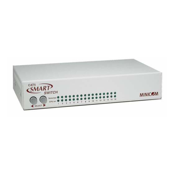
10 11 12 13 14 15 16 Figure 2 Smart CAT5 front panel The figure below illustrates the rear panel of the Smart CAT5 16 port unit. The 8 port model is the same but with only 8 Computer ports. -
Page 7: Pre-Installation Guidelines
10m/33ft 9. Connecting the Smart CAT5 system Connect each computer to the Smart CAT5 system using the appropriate RICC and CAT5 cables. Figure 4 illustrates the Smart CAT5 system connections with the appropriate RICC connected to a PS/2, SUN and USB computer/server. - Page 8 To computer’s keyboard port To computer’s mouse port RICC To computer’s Video card SCSI CAT5 cable to Smart PCI 33Mx32b CAT5 Computer port PCI 33Mx32b PCI 33Mx32b PCI 33Mx32b Figure 5 PS/2 RICC Connecting a SUN RICC Figure 6 illustrates the SUN RICC and its connections.
- Page 9 To Computer’s To Computer’s Video Card Keyboard Port RICC CAT5 cable to Smart CAT5 Computer port Figure 6 SUN RICC Connecting a USB RICC The RICC USB supports Windows 98 SE and later, MAC, SUN and SGI. Figure 7 illustrates the USB RICC and its connections.
-
Page 10: Connecting The Power Supply
3. Connect the mouse’s connector to the Smart CAT5’s Mouse port. 10. Connecting the power supply 1. Connect the Smart CAT5 to the power supply using the Power cable provided. Use only power cord supplied with the unit. 2. Switch on the computers. -
Page 11: Rack Mounting The Smart Cat5
13. Rack mounting the Smart CAT5 Length of the screws used for connection of the bracket to the Smart CAT5 unit shall not exceed 5 mm. Use the L-shaped brackets and screws provided to mount the Smart CAT5 on a server rack as illustrated below. -
Page 12: Rack Mounting The Riccs
SMART CAT5 SWITCH 14. Rack mounting the RICCs You can attach the RICCs to a server rack or computer using the Velcro strips provided. Or connect it using the bracket provided. The figure below illustrates the bracket. Insert screws through... -
Page 13: Cascading Smart Cat5 Switches
USER GUIDE 15. Cascading Smart CAT5 switches You can cascade the Smart CAT5 system. You do so by connecting the lower level Smart CAT5 Switches to RICCs. Follow the connections as illustrated in the figure below. With the Smart CAT5 16 Port model, connect up to up to 256 computers through cascading. -
Page 14: Operating The Smart Cat5 System
SMART CAT5 SWITCH 16. Operating the Smart CAT5 system Switch between the connected computers by either · The front panel Select buttons · Keyboard hotkeys · The OSD (On Screen Display) or Control software The OSD is also the place to adjust various settings as explained below. -
Page 15: Navigating The Osd
USER GUIDE 19. Navigating the OSD To navigate up and down use the Up and Down arrow keys. To jump from one column to the next (when relevant) use the Tab key. To exit the OSD or return to a previous window within the OSD press Esc. 20. -
Page 16: The General Settings
Confirmation label. User (Status U) There are 6 different Users in the Smart CAT5 system. Each User has a Profile set by the Administrator that defines the access level to different computers. There are 3 different access levels; these are explained on page 20. - Page 17 Displaying the OSD of cascaded switches When you have cascaded Smart CAT5 switches, a lower level Switch must have a different OSD display hotkey than a higher level switch. (See page 12.) The hotkeys can be any of the following: ·...
-
Page 18: Serial Port
SMART CAT5 SWITCH To change a lower level hotkey: 1. Connect a keyboard and monitor to the lower level Switch and press Shift, Shift. Its OSD appears. 2. Press F2 and select GENERAL. The General settings window appears. 3. Navigate to the HOTKEY line. -
Page 19: F7 Defaults
Editing the computer name In this window you can edit the computer names with up to 15 characters. When you have a cascaded CAT5 KVM Switch connected to a Computer port give the switch a distinct name. See Figure 14. -
Page 20: The Time Settings
Adjust the HKEY setting in the Ports Settings window of the higher level switch to reflect the lower level switch’s new hotkey: E.g. in Figure 14 above a Smart CAT5 switch is connected to port #3 and its display hotkey is Ctrl, F11. -
Page 21: Users
USER GUIDE 2. Place the cursor over one of the 3 digits and type a new number. Enter a leading zero where necessary. For example, type 040 for 40 seconds. Typing 999 in the LBL column displays the label continuously. Typing 000 – the label will not appear. -
Page 22: Security
SMART CAT5 SWITCH 27. Security In the Settings window navigate to the Security line and press Enter. The Security settings window appears see Figure 17. Figure 17 Security settings window The ‘T’ column on the right hand side stands for Type of password. -
Page 23: Scanning Computers- F4
4. When the image is satisfactory, press Esc. Note! Picture quality is relative to distance. The further away a remote computer is from the Smart CAT5, the lower the image quality, and the more tuning needed. So place the higher resolution computers closer to the manager unit. -
Page 24: Sending Monitor Emulation Information To Riccs - F10
Display Data Channel (DDC) is a VESA standard for communication between a monitor and a video adapter. Input the DDC information of the monitor connected to the Smart CAT5 switch into the memories of all connected RICCs when first installing system. -
Page 25: Control Software System Requirements
· Free Serial port 35. Connecting the RS232 Serial cable To run the software, connect the RS232 Serial cable to the computer containing the software, and to the Smart CAT5. See the figure below. P 110 Computer screens appear here... -
Page 26: Installing And Running The Control Software
CAT5 RS232 Control / Smart CAT5 RS232 Control. To run the software from the CD: Choose Run Smart CAT5 switch RS232 Control Software from CD. Selecting a Com port During the Setup process you will be prompted to choose a Com port. Choose the Com port to which the RS232 Serial cable is connected. -
Page 27: Computer Icons
Check that: · The RS232 Serial cable is connected to the computer’s Serial port and the Smart CAT5 service port. · The Com Port settings in Options / Com Port are set correctly. After changing the Com port exit and re-enter the Control software. -
Page 28: Selecting A Computer
SMART CAT5 SWITCH 40. Selecting a computer To select a computer: Click on the computers icon. The system switches to that computer. The connected icon appears with a red background . Control and monitor the selected computer from the keyboard and mouse connected to the Smart Switch. -
Page 29: Renaming A Computer
USER GUIDE 45. Renaming a computer To rename a computer: 1. Type the new name in the box below the computer icon. 2. Click to send the new name to the system. Or click Save or Save As from the File menu to save the change in a file and not alter the OSD names. -
Page 30: Settings
SMART CAT5 SWITCH 48. Settings Choose Settings from the Edit menu. The Computers’ Properties box appears. See Figure 24. Figure 24 The Computers’ Properties box Here you can edit all the data that can be edited in the OSD. This includes: Scan times, Timeout, Confirmation label display time, Keyboard type/mode, User access, Password mode, Autoskip mode, and Switch/System hotkey. -
Page 31: Loading A Saved Configuration
There is no need to press 52. Password protection When the Smart CAT5 system is password protected, the Control software behaves in exactly the same way as the OSD. You must type in the required password to access the Control software. The access you gain depends on the security status – exactly as with the OSD. -
Page 32: Upgrading The Smart Cat5 Firmware
SMART CAT5 SWITCH User (Status U) There are 6 different Users in the Smart CAT5 system. Each User has a Profile that defines the access level to different computers. There are 3 different access levels. These are: · Y – Full access to a particular computer ·... -
Page 33: Connecting The Rs232 Serial Cable
Download the Update software from www.minicom.com and install it on your computer. 58. Starting and configuring the Smart CAT5 Update 1. Start the Smart CAT5 Update software. The Smart CAT5 Update window appears. See Figure 26. Smart Switch RICCs Status... -
Page 34: Verifying The Version Numbers
SMART CAT5 SWITCH The table below explains the functions of the buttons and boxes in the Smart CAT5 Switch Update window. Button or Box Function Selects all RICCs Unselects selected RICCs Starts firmware download Displays the firmware version number Displays the hardware version number... -
Page 35: Obtaining New Firmware
The H/W Version button is grayed out, as there is no hardware relevant to the OSD. The Smart CAT5 Manager version number To verify the Smart CAT5 version number: In the Switch Unit box, check the Smart CAT5 Manager option. Click . The firmware version number appears in the Switch Unit box. -
Page 36: Updating The Firmware
Windows directory. 62. Reset Reset the software for the Smart CAT5 Manager or RICCs when for example the unit hangs or when the mouse fails to work properly. Resetting is done via the Serial port, and avoids the need to shut down the computer. -
Page 37: Ricc Sun Keyboard Emulation
Resetting the Switch or RICC units To reset the Switch or RICC units: 1. For the Switch, check the Smart CAT5 Switch option in the Switch Unit box. For the RICCs, check one or more RICCs in the RICC Units box. -
Page 38: Usb / Sun Combo Keys
SMART CAT5 SWITCH 65. USB / SUN Combo keys The connected PS/2 keyboard does not have a special SUN keypad to perform special functions in the SUN Operating System environment. So when a RICC USB or SUN is connected to a SUN computer, the RICC emulates these SUN keys using a set of key combinations called Combo keys. -
Page 39: Technical Specifications
Platforms Novell 3.12-6, SUN Mouse PS/2, Wheel mouse, Intellimouse, 5-button mouse Resolution 1600x1200@75Hz System cable CAT5/ 5E/ 5+/ 6/ or 7 cables. FTP or UTP 2x4x24 AWG solid wire Transmission Up to 10m/33ft distance Smart CAT5 Switch Dimensions – 8/16 215.0 x 122.0 x 41.5mm / 8.46 x 4.80 x 1.63in... -
Page 40: User Guide Feedback
SMART CAT5 SWITCH 67. User guide feedback Your feedback is very important to help us improve our documentation. Please email any comments to: ug.comments@minicom.com Please include the following information: Guide name, part number and version number (as appears on the front cover). - Page 41 USER GUIDE Regional Offices Germany France Italy Kiel Vincennes Rome Tel: + 49 431 668 7933 Tel: + 33 1 49 57 00 00 Tel: + 39 06 8209 7902 info.germany@minicom.com info.france@minicom.com info.italy@minicom.com www.minicom.com...
Need help?
Do you have a question about the CAT5 and is the answer not in the manual?
Questions and answers