Table of Contents
Advertisement
Advertisement
Table of Contents

Related Manuals for Kathrein MobiSet 4 digital CAP 900


Summary of Contents for Kathrein MobiSet 4 digital CAP 900
- Page 1 Installation and operating manual - Englisch - MobiSet 4 digital CAP 900...
-
Page 2: Table Of Contents
CONTENTS ..........................2 CONTENTS ............ 3 FOREIGN LANGUAGE INSTALLATION MANUAL / DISPOSAL ............ 4 MOBISET 4 CAP 900 COMPONENTS / SCOPE OF DELIVERY ........................... 5 PROPER USE ................. 6 SAFETY INSTRUCTIONS - IMPORTANT NOTES ................... 9 INSTALLATION AND CONNECTION ............11 INSTALLATION OF CABLE GLAND AND MOUNTING PLATE .................... -
Page 3: Foreign Language Installation Manual / Disposal
(http://www.kathrein.de/en/sat/products/franzoesisch.htm). Lei puo avvere la versione italiana delle istruzioni di montaggio dalla nostra rapresentanza (http://www. kathrein.de/include/kontakte_groups_eng.cfm?kontinent=1&gruppe=SAT) piu vicina della sua citta´, oppure scaricarla dalla nostra hompage http://www.kathrein.de/en/sat/products/italienisch.htm) Para obtener la versión española de nuestro manual de instalación, contacte nuestros representantes en su país (http://www.kathrein.de/include/kontakte_groups_eng.cfm?kontinent=1&gruppe=SAT) o bajela de... -
Page 4: Mobiset 4 Cap 900 Components / Scope Of Delivery
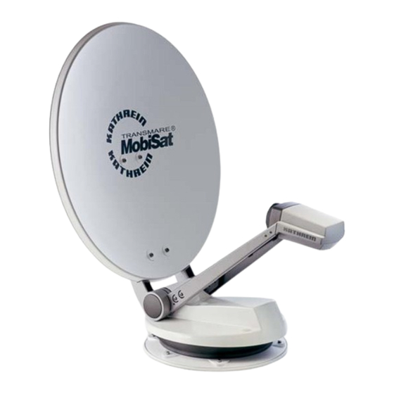
PRODUCT PACKAGE The MobiSet 4 digital CAP 900 consists of: • Turntable complete with control electronics (and GPS receiver), pre-assembled satellite dish and twin LNB •... -
Page 5: Proper Use
PROPER USE (USE FOR THE INTENDED PURPOSE) The MobiSet 4 digital CAP 900 is designed to receive digital TV and radio programs via satellite. The automatic positioner is intended to be used as a turntable for the Kathrein satellite dish. -
Page 6: Safety Instructions - Important Notes
SAFETY INSTRUCTIONS - IMPORTANT NOTES Safety during installation work When carrying out installation work in locations where there is a risk of falling, take appropriate safety precautions, e.g. use of a working platform. Make sure that the vehicle roof is suffi ciently strong and stable to carry out the installation work (risk of damage or collapse of roof). - Page 7 SAFETY INSTRUCTIONS - IMPORTANT NOTES Road Traffi c Licensing Regulations (StVZO) The applicable regulations of the StVZO must be observed in respect of fi xed installation of the turntable on a vehicle which is driven on public highways. In particular, this applies to §§ 19/2; 30 C; 32 (2) and the EC directive 74/483 EEC. Briefl...
- Page 8 SAFETY INSTRUCTIONS - IMPORTANT NOTES Checks before commencing a journey • Before commencing a journey, the antenna must always be lowered into horizontal position (park position). If the antenna collides with a fi xed or moving object, you must check that it is still securely attached.
-
Page 9: Installation And Connection
INSTALLATION AND CONNECTION REQUIRED TOOLS AND EQUIPMENT • Circular cutter, Ø 38 mm • Flat-bladed screwdriver for M5 screws • Drilling machine • Galvanised raised head screws, depending on roof structure (Ø: 5 mm, sheet metal screws D 7981, depending on roof panel structure) or raised head screws D 7985 with shims and nuts •... - Page 10 INSTALLATION AND CONNECTION • When selecting the installation position, take into account the range of movement of the turntable (see the grey shaded area in the graphics). Within this grey area there must be no structures on the roof that would obstruct this movement (risk of collision).
-
Page 11: Installation Of Cable Gland And Mounting Plate
INSTALLATION OF CABLE GLAND AND MOUNTING PLATE Note: If you have previously used a Kathrein HDM140/141 fl exible satellite mast or another mast with a diameter of 34 mm, you can continue using the existing gland hole in the roof (if space allows). - Page 12 INSTALLATION AND CONNECTION • For very thin roof panel materials and insuffi cient purchase in the insulating material, through holes (Ø: 5.5 mm) into the interior of the vehicle are necessary; galvanised M5 raised head screws of suffi cient length should then be used. Make sure that you use a suffi...
-
Page 13: Installation Of Turntable
INSTALLATION AND CONNECTION • Before starting adhesive work, note that the optimum processing temperature of materials to be glued and the adhesive sealant is between +15 °C und +25 °C. Prepare all necessary fastening elements and tools. • Prepare the tube of adhesive sealant in accordance with the instructions enclosed with the tube. •... - Page 14 INSTALLATION AND CONNECTION Figure: E1 Master coaxial cable (marked red) Figure: E2 Gasket • Lift up the turntable and place it carefully on the mounting plate facing in the direction of travel (see illustrations Fig. E) (do not step on the plug connector and do not kink/crush the cables!) The through holes on the turntable must be perfectly aligned with the threaded holes on the mounting plate.
- Page 15 INSTALLATION AND CONNECTION • To prevent water vapour from inside the vehicle reaching the turntable through the roof gland, thread the three cables through the sealing gasket supplied (see Fig. E2) and insert this into the roof gland until it reaches the stop.
-
Page 16: Installation Of The Ufs 740Sw Receiver
INSTALLATION AND CONNECTION 11 AF spanner. Do not try to pull the cables from the unit. This could damage the cables or loosen the cable connections. • Apply a little adhesive sealant to the six threaded holes in the mounting plate and screw the fastening screws into the thread. - Page 17 INSTALLATION AND CONNECTION SUSPENDED INSTALLATION Remove the wood screws supplied from their transport attachment on the underside of the respective mounting piece (2 pieces). Vertically insert each mounting piece into the fi fth slot from the edge, as shown in Fig. 1. Then push each mounting piece downwards and outwards (see Fig.
-
Page 18: Laying Cables And Connecting The Turntable
INSTALLATION AND CONNECTION LAYING CABLES AND CONNECTING THE TURNTABLE • Lay the master coaxial cable (marked red) to the UFS 740sw and the second coaxial cable to the second receiver. If you are not using a second receiver, we recommend that you lay the second coaxial cable in any case, so that it is available should you ever need it. -
Page 19: Functional Instructions For Connection To The On-Board Power Supply
INSTALLATION AND CONNECTION Only for connection in a motor home, not in a caravan! • The third, green connecting cable, marked “IGNITION” allows you the option of connection to a circuit in the vehicle that is activated when the ignition key is turned and then carries a continuous 12 V supply. This type of connection ensures that when the engine is started the antenna is automatically lowered into the park position (the receiver does not need to be turned on). -
Page 20: Connection Example For 12 V Battery Connection
INSTALLATION AND CONNECTION CONNECTION EXAMPLE FOR 12 V BATTERY CONNECTION Figure: G Important: For operation with two batteries, it must be ensured that the ignition signal earth has the same potential as the power supply battery earth for the turntable. Non-compliance means that the Important: automatic lowering function will not... -
Page 21: Reception Range / Footprint
RECEPTION RANGE / FOOTPRINT The footprint is the reception area on the earth that a satellite covers with its transmission beam (spot), within which satellite reception is possible. The transmission power is at its greatest in the centre of this spot –... -
Page 22: Dismantling For Servicing
Before exchanging the UFS 740sw, fi rst move the turntable to the park position. ADDRESS OF THE SERVICE CENTRE Electronic Service Chiemgau GmbH Bahnhofstraße 108 83224 Grassau, Germany Phone: +49 8641 9545-0 Fax: +49 8641 9545-35 and -36 Internet: http://www.esc-kathrein.de e-mail: service@esc-kathrein.de... -
Page 23: Manual Lowering To Park Position
MANUAL LOWERING TO PARK POSITION If a defect arises in the electronic controls, after some disassembly work the satellite dish can be returned to the park position (horizontal position) manually. Following this however recalibration by an authorised workshop is always necessary. Driving to the nearest workshop with the antenna extended at a moderate speed and taking into account the increase (+ 77cm) in the vehicle height is an option and is preferable to manual lowering! -
Page 24: Manual Lowering
MANUAL LOWERING TO PARK POSITION MANUAL LOWERING In the centre of the antenna (arrowed) there are two plastic caps, one to the left and one to the right. Lever them off with a narrow fl at-bladed screwdriver. Behind each cap is an M8 hexagon head screw. Unscrew these using a 13 mm socket wrench. -
Page 25: Technical Data
TECHNICAL DATA Direction of travel Type CAP 900 Order no. 20310012 2 outputs switchable: V/H (14/18 V), low/high (0/22 kHz) LNB supply voltage vert.: 11.5-14, horiz.: 16-19 Input frequency 10.70-12.75 Output frequency 950-1950/1100-2150 Oscillator frequency (L.O.) 9.75/10.60 System quality (G/T) 11.3/12.5 GHz dB/K 16.9/17.9 Supply voltage (vehicle battery) -
Page 26: Sikaflex 291 Data Sheet
SIKAFLEX ® 291 DATA SHEET... -
Page 27: Sikaflex 291 Technical Datasheet
® SIKAFLEX 291 TECHNICAL DATASHEET... -
Page 28: Cap 900 Operating Manual
CAP 900 OPERATING MANUAL The operating manual for the CAP 900 starts on this page If, despite studying this operating manual, you still have questions about getting started with the unit or using it correctly, or if unexpected problems occur, please contact your specialist dealer. -
Page 29: Important Information For Cap 900 Before Setup
IMPORTANT INFORMATION FOR CAP 900 BEFORE SETUP This section of the UFS 170 operating manual for the turntable assumes that the UFS 170 and the turntable have been properly installed and connected, as described in the installation and operating manuals! If you have not yet done so, read the safety instructions at the beginning of the UFS 740sw operating manual and follow them when handling the UFS 740sw and the turntable! -
Page 30: First Installation
FIRST INSTALLATION Before using your unit for the fi rst time, read the “Safety Instructions – Important Information” and “Installation and Connection” sections. In the “Installation and Connection” section you will fi nd a sample confi guration (one for a motor home and one for a caravan). Do not connect the unit to the power supply until all installation work has been properly carried out. - Page 31 FIRST INSTALLATION The following display appears: Use the buttons here to select the settings for your TV set. When doing this, refer to the operating instructions for your TV set! TV format Select the TV‘s picture format. Either 4:3 or 16:9 Screen display Here you select the type of screen display, depending on the setting of your TV format:...
- Page 32 FIRST INSTALLATION The following display appears: System Use the buttons at “System” to select “CAP 900”. Then press the (green) button (channel scan “item 4/5” is skipped). The following display appears: Set Local Time Use the buttons to set the time zone variation from UTC (formerly GMT) (e.g. for Germany +1 hour).
-
Page 33: Alignment (Satellite Search)
ALIGNMENT (SATELLITE SEARCH) The antenna is aligned automatically. After the UFS 740 has been switched on, the turntable automatically moves to the last channel received and the associated satellite position (e.g. ARD/ASTRA). This works because every satellite broadcasts its own identifi cation signal, which is automatically identifi ed by the turntable. -
Page 34: Manual Correction
ALIGNMENT (SATELLITE SEARCH) MANUAL CORRECTION At the margins of the footprints of a satellite (e.g. after a slight change of position), it may be necessary for you to manually correct the setting (not normally required). It is also possible to manually correct the fi ne tuning. -
Page 35: Channel (Satellite) Selection
CHANNEL (SATELLITE) SELECTION By pressing the buttons all channels can be selected in the sequence that they appear in the current channel list and its sorting. Press the (blue) button to switch between TV and radio channels. CHANNEL SELECTION FROM THE CHANNEL LIST Providing you are not in a menu, pressing the button calls up the channel list. -
Page 36: Change Of Location / Timer Programming
CHANGE OF LOCATION / TIMER PROGRAMMING After a change of location, the antenna moves to the last position selected. After initialisation, you will therefore see the following display (example, as it depends on the last selected position): For slight changes of location, the antenna can fi... -
Page 37: Reset/Parking
RESET/PARKING RESETTING THE MOTORISED ANTENNA Press the button to switch to the main menu. The buttons and button allow you to call up the submenus (“Settings”, “Antenna Confi guration”). Use the buttons to navigate to the sub-item “Reset turntable antenna” and now press the button. -
Page 38: Parking The Turntable
RESET/PARKING PARKING THE TURNTABLE You have three options for “parking” the antenna. The antenna can be moved to park position by pressing the button twice. Press the button to switch to the main menu. The buttons and button allow you to call up the submenus (“Settings”, “Antenna Confi... -
Page 39: Special Messages From The Turntable
SPECIAL MESSAGES FROM THE TURNTABLE SYSTEM PROTECTION MESSAGES The following messages are shown on the screen to protect your reception system and the on-board power supply: The power supply to the turntable is insuffi cient (battery voltage below minimum value). The turntable can still be moved, but communication errors can occur between the UFS 740sw and the turntable (e.g. - Page 40 SPECIAL MESSAGES FROM THE TURNTABLE The turntable motor temperature is in the critical range. The controls can move the turntable only to a known satellite position or to the park position. In addition you receive the message “Last Move done” (to allow the turntable motor the opportunity to cool down, no movements of the turntable are permitted for a few minutes).
-
Page 41: Messages Arising From Software Problems
SPECIAL MESSAGES FROM THE TURNTABLE The motorised antenna has reached the mechanical stop or is jammed! Check whether the turntable is obstructed (e.g. by a branch). MESSAGES ARISING FROM SOFTWARE PROBLEMS A serious software error has occurred. Reset the turntable in the CAP menu, or contact our service centre. The motorised antenna software is defective. -
Page 42: Further Messages
SPECIAL MESSAGES FROM THE TURNTABLE FURTHER MESSAGES The receiver has lost communication with the turntable. Check the connection between the UFS 740sw and the turntable. The two components must be connected to each other using the master cable (marked red). The connection to the turntable is defective. -
Page 43: Declaration Of Conformity
DECLARATION OF CONFORMITY... - Page 44 Internet: http://www.kathrein.de KATHREIN-Werke KG • Anton-Kathrein-Straße 1 - 3 P.O. Box 100 444 • 83004 Rosenheim GERMANY...
Need help?
Do you have a question about the MobiSet 4 digital CAP 900 and is the answer not in the manual?
Questions and answers