
Related Manuals for Ravel RE-2504


Summary of Contents for Ravel RE-2504
- Page 1 RE – 2504 RE – 2508 Automatic Fire Alarm Control Panel (Protective premises Unit) Installation, Commissioning & Operating User Manual...
- Page 2 Fire Alarm System Limitations An automatic fire alarm system–typically made up of smoke detectors, heat detectors, manual Call Points, audible warning devices, and a fire alarm control with remote notification capability–can provide early warning of a developing fire. Such a system, however, does not assure protection against property damage or loss of life resulting from a fire.
- Page 3 The amount of "smoke" present may be insufficient to alarm smoke detectors. Smoke detectors are designed to alarm at various levels of smoke density. If such density levels are not created by a developing fire at the location of detectors, the detectors will not go into alarm. Smoke detectors, even when working properly, have sensing limitations.
- Page 4 Please note that: • Strobes can, under certain circumstances, cause seizures in people with conditions such as epilepsy. • Studies have shown that certain people, even when they hear a fire alarm signal, do not respond or comprehend the meaning of the signal.
- Page 5 NOTES: RE / DD / UM / 2508 V1.2- 01...
- Page 6 RE / DD / UM / 2508 V1.2- 01...
- Page 7 It is imperative that the installer understands the requirements of the Authority Having Jurisdiction (AHJ) and be familiar with the standards set forth by the following regulatory agencies: • Underwriters Laboratories Standards • NFPA 72 National Fire Alarm Code NFPA Standards This Fire Alarm Control Panel complies with the following NFPA Standards: NFPA 72 National Fire Alarm Code for Local Fire Alarm Systems.
-
Page 8: Table Of Contents
Table of Contents CHAPTER 1: Introduction ………….......……......9 1.1: System Design & Planning..........9 1.2: General .………..............9 1.3: Fire Alarm Procedure …..........10 1.4: User Responsibility…............10 1.5: Routine test....…........………….11 CHAPTER 2: Product Description ......……....12 2.1: Product Features ............13 2.2: Specifications ............…..15 2.3: Controls and Indicators ..........16 2.3.1: Controls..………........…………...16 2.3.2: Indication …………………….…..….…………………..17 2.3.2.1 LED Indication………………………………………….17... - Page 9 CHAPTER 5: Operating Instructions...….....……………..…..51 5.1: Switch Functions ……………………......51 5.2: Indications ........…......…53 5.3: Operation..............….55 5.3.1: Normal Monitoring Mode……………………………….55 5.3.2: Fire Alarm Condition..........….. 55 5.3.3: Supervisory………..…………………………....57 5.3.4: Fault………………………….……………………………58 5.3.5. Disable / W.T……………………………………………..59 5.3.6: Alarm Verification ………………………………………..61 CHAPTER 6: Servicing……………………………..…………………….62 6.1: Installation / Replacement of PCB……………………..…62 6.2: Lamp Test…………………………………………………...64 6.3: Walk test…………………………………………………….64 6.4: System Power / Size …………………………………..….65...
-
Page 10: Chapter 1: Introduction
Chapter 1: Introduction This manual is intended as a complete guide to the 4/8 Zone Conventional Fire Alarm Control Panels. This manual provides complete information on installation, commissioning, Operating Instructions, programming guide, service, and maintenance procedures with full technical details. 1.1 System Design and Planning It is assumed that the system, of which this control panel is a part, has been designed by a competent fire alarm system designer in... -
Page 11: Fire Alarm Procedure
1.3 Fire Alarm Procedures In accordance with NFPA – 72, written procedures should be laid down for dealing with alarms of fire, fault warnings, and the isolation of any part of the system. The responsible person should ensure that users of the system are instructed in its proper use and are familiar with the procedures. -
Page 12: Routine Test
1.5 Routine Testing In order to ensure that the system is fully operational, and to comply with the requirements of UL864 Standard & NFPA – 72, the following routine attention is recommended: Daily - Check the panel to ascertain that it indicates normal operation. If any fault is indicated check that it has been recorded and the appropriate actions have been taken e.g. -
Page 13: Chapter 2: Product Description
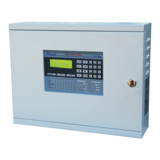
Chapter 2: Product Description The RE – 2504 & RE – 2508 is a 4 & 8zone microprocessor based conventional Fire Alarm Control Panel. The Panel accepts water flow devices, conventional input devices like 2 wire and 4 wire smoke detectors, Manual Call Points and other normally open contact devices. -
Page 14: Product Features
Product Feature 4/8 Class B initiating device circuit (IDC). All zones accept smoke detectors and any normally open contact device. Any Zone can be configured as Alarm or supervisory Zone. 2 Class B Notification Appliance Circuits (NAC). Fully complies with UL -864 and NFPA-72. Rugged CRCA sheet with powder coated finish. - Page 15 Figure – 1 RE / DD / UM / 2508 V1.2- 01...
-
Page 16: Specifications
Specification Primary Power – CN1 (RE-SMPS-4A-R1) 220VAC ± 10%, 50 Hz, 2.5Amps. Standby Power – CN10 24v D.C (2 Nos of 12v, 12Ah Sealed Lead acid battery). Operating Condition Operating Temperature – 15 - 25° C/60-77° F. Relative Humidity – 93 ± 2% RH (non-condensing) at 25 ±2° C/77 ±3° F. Charging Circuit Charging Voltage –... -
Page 17: Controls And Indicators
Common Three Form – C Relays – CN2, CN3, CN4 Relay Contact Rating: 2Amps @ 30 VDC, 2Amps @ 30VAC. Power Factor: 0.6 Control and Indication Figure – 2 2.3.1. Controls: ACK. Key: To mute local buzzer in alarm condition. To mute local buzzer in Supervisory or fault condition. -
Page 18: 2: Indication
EVACUATE: To activate External NACs Manually. User or Admin password protected. CURSOR KEYS To move the curse point in the LCD as required. ENTER Key: To accept the programmed or edited menu, mode or value in the LCD. MENU Key: To enter into the Main Menu in the LCD. -
Page 19: 2.: Lcd Indication
2.3.2.2 LCD Indication The LCD is mainly used for the programming of the panel. It also indicates all events along with the LED indications except system on and system fault. Programmed zone wise location details can be viewed. 2.3.2.3 Local Buzzer A piezo buzzer provides separate and distinct sounds for alarm, trouble and supervisory conditions: Alarm –... -
Page 20: Internal Arrangement
Figure – 4 Internal Arrangement Figure – 5 RE / DD / UM / 2508 V1.2- 01... -
Page 21: Components
Components Master Board (RE – 25XX – ZB – R1) Figure – 6 The Zone board contains the primary components and wiring interface connectors. Display Board (RE – 25XX – DISP – R1) The Display Board contains the system CPU, LED Display, LCD unit and Control keys. - Page 22 Power Supply Board (RE – SMPS – 4A – R1) Figure – 8 This Power supply Board gives the 30V DC output for the Zone Board. This board is SMPS type, it gives the output for 2.5Amps Max (4Amp During Initial condition). Cabinet The Cabinet measures 440mm width X 340mm Height X 120mm Depth and space is provided for 2 x 12 Volt 7Ah Batteries,...
-
Page 23: Chapter 3: Installation
Chapter 3: Installation Installation Precaution Installation Precautions WARNING - Several different sources of power can be connected to the fire alarm control panel. Disconnect all sources of power before servicing. Control unit and associated equipment may be damaged by removing and/or inserting cards, modules, or interconnecting cables while the unit is energized. - Page 24 Verify that wire sizes are adequate for all IDC’s loops. Most devices cannot tolerate more than a 10% I.R. drop from the specified device voltage. Adherence to the following will aid in problem-free installation with long-term reliability: Like all solid-state electronic devices, this system may operate erratically or can be damaged when subjected to lightning- induced transients.
-
Page 25: Mounting Details
Mounting Details Figure – 9 Remove all the Boards before placing the panel in its mounting position. Place the panel in its mounting position and fix the panel to the wall using the slots of the four screws. Ensure the enclosure and the inner parts of the panel are given sufficient protection during installation. -
Page 26: Panel Wiring
Panel Wiring Warning: Several different sources of power can be connected to this panel. Disconnect all sources of power before servicing. The panel and associated equipment may be damaged by removing and / or inserting cards, modules or inter connecting while this unit is energized. - Page 27 RE – 2508 Power Supply Circuit Board (RE – SMPS – 4A – R1) Figure - 10 RE – 2508 Power Supply Monitor Circuit Board (RE –Monitor) Figure - 11 RE / DD / UM / 2508 V1.2- 01...
- Page 28 RE – 2508 Main Circuit Board (RE – 25XX – ZB – R1) Figure – 12 RE / DD / UM / 2508 V1.2- 01...
- Page 29 Field Wiring Diagram Figure – 13 RE / DD / UM / 2508 V1.2- 01...
- Page 30 Mounting OF RE - Monitor Figure - 14 Figure - 15 RE / DD / UM / 2508 V1.2- 01...
-
Page 31: Initiating Device Circuits
Initiating Device Circuit No. of Initiating circuit: 4 Zone for RE – 2504 8 Zone for RE – 2508 Type Class B Style B / C Programmable Wire Size 1.5 sq. mm Max. Operating Voltage 14 - 21 VDC Nominal (Max.) Terminal Loop Resistance 100 Ω... -
Page 32: Output Circuits
Figure – 16 Output Circuits 3.5.1 Notification Appliance Circuits No. of NAC 2 Ckts. Type Class B Style Current 0.6A (Each) Terminals CN5, CN6 Monitoring Device 3K9 (EOL) Wire Size 1.5 sq. mm Max. Compatible Device : Refer Chapter 9. NOTE: For Synchronized ANSI Pattern Output External Synchronizing Module to be used. -
Page 33: 2: Resttable Power
Figure – 17 3.5.2 Resettable Power (300mA) Output Voltage 24VDC Nominal Current 0.3A Max. Output Terminal Wire Size 1.5 sq. mm Max Monitoring Device RE – MONITOR (Refer Chapter 9) Monitoring Terminal : CN9 Link 3K9 Max. (Refer Chapter 9) NOTE: The Link should be disconnected after connecting monitoring device. -
Page 34: Standard Relay Output
Standard Relay Output Circuits No. of Relay Output 3 (Fire, Fault, Supervisory) Contact Voltage 30 VDC Nominal Current Rating Type of Relay Form – C Figure – 19 Figure – 20 RE / DD / UM / 2508 V1.2- 01... -
Page 35: Chapter 4: Programming Instructions
CHAPTER 4: Programming Instructions Menu Key Flow Diagram: MENU KEY - FLOW DIAGRAM MENU ACC ESS LEVEL 2 (USE PASSWOR D) SUPPRESED PROGRAM ABOUT HISTORY EVENTS SUPERVISORY FAULT ZONE MODE SETTINGS FEATURES Zno.: 1 2 3 4 5 6 7 8 Zone Wirin g Mde: F F F F F F F F Class- B Style-C... -
Page 36: Programming
Programming: The MENU key is used to enter into the programming mode for changing the zone details and other settings. The various steps involved in this menu are shown as flow chart 4.1. After entering into the menu, screen will be as below, 1. - Page 37 X = Zone Number Y = F / S / A / W / D mode. F – Fire, S – Supervisory, A – Alarm Verification, W – Walk test, D - Disable The zone is selected by using the right / left arrow keys, the mode can change using the ‘#’...
- Page 38 Walk test: In this mode the selected zone is used to check all the loop devices manually one by one. The signal from the Initiating device will cause the panel in the alarm mode. The panel automatically get silenced and reset after a specific period without activating the fire relay.
-
Page 39: Zone Wiring
Alarm Verification: this mode, detectors connected in the selected zone are used to check and confirm that smoke detector activates the verification alarm. The smoke detectors should be connected to the zone which going to select as for alarm verification. Note: Use only the alarm verification facility to zone loop in which the smoke detectors are used. -
Page 40: Auto Silence
Table 4.2.1. Feature Programming: Permitted Options Features in UL? [Y/N] Alarm Zone Style – C Style – B Supervisory Mode Resettable Latching Walk Test Audible Silenced Auto silence Disabled Enabled: 1 - 999Secs Silence Inhibit Disabled Enabled: 1 – 999Secs AC Loss Delay Enabled: 1 –... - Page 41 4.2.1.2.1 Alarm Zone: The zones circuit is designed for the class-B wiring. The style of wiring can be changed using this option. The Style of class-B can be changed as Style- B or Style-C by pressing ‘#’ key from the panel key pad.
- Page 42 Auto Silence Enabled: XXX Secs. <Prev Next> xxx – represents silence time; yy – represents feature number 4.2.1.2.5 Silence Inhibit: Silence Inhibit feature prevents silencing of Notification Appliance Circuits, using the Silence switch or Reset switch, for the amount of time corresponding to the selected option, after the NAC’s are activated.
- Page 43 When you enter into this mode the screen will be as below. AC Loss Delay Enabled: XXX Mins <Prev Next> xxx – represents silence time; yy – represents feature number 4.2.1.2.7 Trouble Reminder: The Trouble Reminder feature provides an audible reminder that a fire/supervisory/Fault still exists on the panel after the control panel has been silenced.
- Page 44 When you enter into this mode the screen will be as below. Title: Ravel Electronics 4.2.1.3.2. Location Program: By selecting the number 2 from the Settings screen, system enters into the Location Program change mode. This mode is used to enter the name of the zone location of the particular zone.
- Page 45 Initially the system shows all zones as ‘Loc. not Entered’. The zone number can be selected using the arrow keys, which has to be changed or entered, press the ‘enter’ key. Then it goes to edit mode, after entering or changed the location press ‘Enter’...
- Page 46 4.2.1.3.3.1. User Password: By selecting the number 1 from the Password screen, system enters into the user Password change mode. The display screen of this mode showed as below. The Default Password is”1234”. The Password should be four digit. Old Password? Old Password? XXXX New Password? Old Password? XXXX...
- Page 47 4.2.1.3.3.2. Admin Password: By selecting the number 2 from the password screen, system enters into the Admin Password change mode. The display screen of this mode showed as below. The Default Password is”56789”. The Password should be five digit. Old Password? Old Password? XXXXX New Password? Old Password? XXXXX...
- Page 48 4.2.1.3.4. Date & Time: By selecting the number 4 in the keypad from setting menu, it enters into the date & Time change Mode screen. In this mode, the date and time of RTC (Real Time Clock) is set by using the keypad. The display will show as below.
-
Page 49: Suppressed Events
XX – Hour; YY – Minute. When entered into this mode cursor blinks on the Time, you can change the time by using alphanumeric key pad. After entering the details press enter key to accept the changes and update. The display shown above is for 24 hours format and 12 hours format is shown as below. - Page 50 Note: Through suppressed events feature you can view the fault occurred currently during alarm condition. 4.2.2.1 Supervisory The suppressed supervisory events are viewed by selecting the number 1 from the suppressed events screen. The display screen as shown below. Supervisory [ x/y ] Zone X If there is more than one supervisory events the screen shown as below.
-
Page 51: History
4.2.3 History By selecting the number 3 from the menu screen, system enters into the history mode. The lost 10 events of the panel are shown in the history. In this mode the events (alarm, silence and reset) occurred in the panel can be viewed in the history log events. -
Page 52: Chapter 5: Operating Instructions
Chapter 5: Operating Instruction Figure – 23 Switch Functions The Keys, which are non-masked, are used for the general operation of the Fire Alarm Panel. The Non-masked keys are Silence, Reset, Ack., Evacuate and Enter keys. SILENCE Key: When the silence key is pressed, after entering the user or admin password the following will occur: The silenceable Notification Appliance Circuits will be turned OFF The Silence LED will be turned ON... - Page 53 RESET Key: When the Reset key is pressed, after entering user or admin password, the control panel will: Clear the status LED’s. Bring back the LCD display to the healthy condition. Turn off the Notification Appliance Circuits. Reset fire zones by temporarily removing power. Restore all system relays to normal.
-
Page 54: Indications
This is the only LED glowing in the normal monitoring condition. The LCD Display as shown below. 12/07/08 10:10 Ravel Electronics System Healthy MAINS FAIL: Whenever the Main Supply (220v A.C) fails, the Mains fail LED will be illuminated and it also indicated in LCD with toggle Buzzer tone. - Page 55 SILENCED: This LED will glow when the silence key is pressed in fire condition only. NAC FAULT: Whenever there is any fault in Notification Appliances Circuits like NAC loop Open / Short / Earth fault, it will be identified by COMMON NAC FAULT LED.
-
Page 56: Operation
Circuits will be off, all relays are in their normal state and the onboard buzzer will be off. When the system is in normal condition the LCD screen will be as below. DD/MM/YY HH:MM Ravel Electronics System Healthy 5.3.2. Fire Alarm Condition: When the control panel detects Fire via the Detector / MCP, the panel will cause the following: The corresponding ZONE FIRE red LED will blink. - Page 57 Turn off the zone fire LED. Turn off the Fire relay. Store the reset operation in the history. The LCD screen will be as below. DD/MM/YY HH:MM Ravel Electronics System Healthy RE / DD / UM / 2508 V1.2- 01...
-
Page 58: 3: Supervisory
5.3.3. Supervisory: When the control panel detects supervisory signal via the any normally open contact devices, the panel will cause the following: The corresponding zone supervisory LED will blink. The common supervisory LED will glow. Turn on the panel buzzer with intermittent buzzer tone (pulse 0.25sec ON and 0.25sec OFF). -
Page 59: 4: Fault
Turn off the zone supervisory LED. Turn off the supervisory relay. The LCD screen will be as below. DD/MM/YY HH:MM Ravel Electronics System Healthy Note: If the supervisory mode is selected as resettable, the resetting the zone is not required. The zone is retrieved automatically after clearing the supervisory condition. -
Page 60: Disable/W.t
Turn off the zone fault LED/ NAC fault / power fault LED. Turns off the buzzer tone. Deactivate the fault relay. The LCD screen will be as below. DD/MM/YY HH:MM Ravel Electronics System Healthy Note: The Fault occurred will not affect the other normal functions of the panel 5.3.5. Disable/W.T: Disable: The any Zone can be Disabled / Enabled in zone mode through the programming section 4.2.1.1 Page 34. - Page 61 Walk Test: Disable/W.T LED Blinking identifies the corresponding Zone, which is under walktest. If this LED is illuminates continuously then it identifies that particular zone is disabled. The walk test mode helps the user to test each device in that particular zone by a single person.
-
Page 62: 6: Alarm Verification
5.3.6. Alarm Verification: This Alarm verification feature is applicable only to the IDC’s in the zone in which only smoke detectors are used. If the alarm verification is selected IDC, the smoke detector activation will cause the FAP to reset the detector by removing the power for 3.5 Seconds. -
Page 63: Chapter 6: Servicing
Chapter 6: Servicing: Installation/Replacement of PCB: Remove the screws of PCB, which has to be change and remove the PCB from the mounting position and place the new PCB in that same position as shown below. Mounting position for Main Circuit board (RE – 25XX – ZB – R1): Figure –... - Page 64 Mounting position for Display board (RE – 25XX – DISP – R1): Figure – 26 Mounting position for Power supply unit (RE – SMPS – 4A – R1): Figure – 27 RE / DD / UM / 2508 V1.2- 01...
-
Page 65: Lamp Test
Lamp Test: The lamp test function done by pressing ‘0’ key in system (Panel) is normal condition. In this mode, all the LED’s are checked for good condition by glowing all LED’s. Walk Test Mode: The RE – 2508 provides the capability to perform a walktest of the system without triggering the Fire Relay, alarm output (NAC) relay. -
Page 66: System Power / Size
• Display all zone troubles as they occur • Display all system troubles as they occur Note: 1. If any one zone is in walktest, then other zones will operate normal condition. 2. The actual alarm zone cannot be selected for walktest mode. -
Page 67: Trouble Shooting
Trouble Shooting: Condition Root Cause Remedy There is no No power to the Check Primary (AC) indication on Panel power and Standby the panel power. During Mains fail May be battery low Check the Battery condition Battery (<21.6V) or the voltage and charge the fault LED is battery reaches the... -
Page 68: Chapter 7: Calculation Of Battery Size
Chapter 7: Battey Calculation Use Table 7.4 to calculate the total standby and alarm load in ampere hours (AH). This total load determines the battery size (in AH), required to support the control panel under the fail of the AC Power Supply. -
Page 69: Chapter 8: Wire Requirement
Chapter 8: Wire Requirements Connecting external system accessories to the RE - 2508 main circuits must be carefully considered to ensure proper operation. It is important to use the correct type of wire, wire gauge and wire run length per each RE - 2508 circuit. Reference the chart below to specify wire requirements and limitations for each RE - 2508. -
Page 70: Chapter 9: Compatible Devices
Chapter 9: Compatible Devices (ID: CD 01) The compatible devices which are connected with this panel are given below: Compatible IDC’s: Apollo 65A Series – Model: 55000-226 - 16 Nos / Zone. System Sensor 100 Series – Model: 2151 - 16 Nos / Zone. System Sensor Beam Smoke Detector –... -
Page 71: Chapter 10: Abbreviation
Chapter 10: Abbreviation The short forms, which are given in this manual, are abbreviated below, Ravel Electronics Pvt Ltd., NFPA National Fire Protection Association Alternating Current Direct Current CRCA Cold Rolled Carbon Alloy Light Emitting Diode Output millimeter no(s). number(s) - Page 72 Ravel Electronics Pvt Ltd., 150A, Electronic Industrial Estate, Perungudi, Chennai – 600096, India. Web: www.ravelfirepanels.com Email: marketing@ravelfirepanels.com RE / DD / UM / 2508 V1.2- 01...
Need help?
Do you have a question about the RE-2504 and is the answer not in the manual?
Questions and answers