Advertisement
Quick Links
Advertisement

Related Manuals for Star Trac Inspiration Strength IP-S4306


Summary of Contents for Star Trac Inspiration Strength IP-S4306
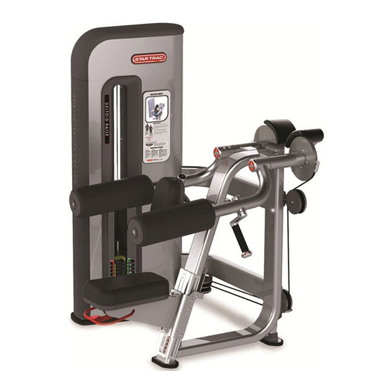
- Page 1 DELTOID RAISE IP-S4306 INSTALLATION INSTRUCTIONS...
- Page 2 Copyright 2009. Star Trac by Unisen, Inc. All rights reserved, including those to reproduce this book or parts thereof in any form without first obtaining written permission from Star Trac. Every effort has been made to keep this information current; however, periodically, changes are made to the information herein, and these changes will be incorporated into new editions of this publication.
-
Page 3: Installation Instructions
• All Star Trac Strength equipment MUST be secured to the floor using either 10mm or 3/8in. (grade 5 minimum) bolts. To accommodate this there are four mounting points inside the weight stack and one in either of the small feet. - Page 4 REMOVE THE SHROUDS: Using a 4MM hex key remove the (M6,30MM,Button Head Bolt) from the rear of the weight stack. Save this bolt as you will need it to re-install later. After the bolt has been removed rotate the black TOP BUMPER towards the front of the weight stack then lift it off and set aside.
- Page 5 INSTALLING THE CAM / COUNTER BALANCE Spacer Install a spacer (26mm ID x 1.5mm thick) onto the shaft of the CAM / COUNTER BALANCE assembly. Weight Frame Side Insert the CAM / COUNTER BALANCE assembly into the bearing tube. Note cable mount position and orientation as shown on picture for proper placement.
- Page 6 ATTACHING THE PULLEYS: Unwrap the UPPER and LOWER PULLEY Assy with cables routed as Upper Inserts (4x) shown. Align the UPPER PULLEY BRACKET Lower with the upper inserts of the main Inserts (6x) vertical tube. Secure with four (M8, 25MM, Socket Head Bolts) and four (M8, Washers) Repeat Step 2 with the LOWER PULLEY BRACKET and secure with six...
- Page 7 GUIDE ROD LUBRICATION: Use a general purpose LUBRICANT that does not contain Teflon or solvent (such as 3-in-ONE® oil.) Apply the LUBRICANT to a cotton cloth, then run the cotton cloth up and down the guide rods as needed to apply a thin coat. Also apply oil to the incremental weight guide tracks.
- Page 8 INSTALLING THE SHROUDS: Insert the SHROUDS from the top sliding downward. The SHROUDS have seven hooks for mounting. Before the shroud can be slide down into place the SHROUD hooks need to be aligned with the corresponding mounting slots found on the weight frame of the equipment.
- Page 9 MACHINE CLEARANCE AND SPACING For the safe operation of Inspiration Strength™ Star Trac recommends that a clearance of 24 inches (60.96cm) be maintained between and behind machines including moving arms and levers. To insure safe entry and exit to each unit a walkway of at least 36 inches (91.44cm) inches is recommended front of, or on the entry side of each machine.
- Page 10 Page 10...
- Page 11 Page 11...
- Page 12 STAR TRAC 14410 Myford Road Irvine, California 92606 Telephone: (800) 228-6635, (714) 669-1660 Fax: (714) 508-3303 www.startrac.com Part No. 620-7935, Rev B., 21 Aug 09...
Need help?
Do you have a question about the Inspiration Strength IP-S4306 and is the answer not in the manual?
Questions and answers