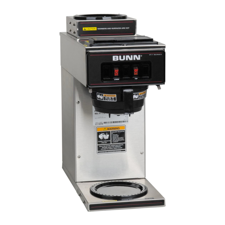
Bunn VP17 Operating & Service Manual
Hide thumbs
Also See for VP17:
- Installation manual ,
- Illustrated parts catalog (26 pages) ,
- Operating & service manual (19 pages)
Advertisement
BUNN
N
N
ER
ER
NT
NT
U T
U T
IO
IO
CA
CA
D DE
D DE
C A
C A
AR
AR
DI SC
DI SC
!
IF :
IF :
D
D
KE
KE
HE
HE
D
D
PT
PT
Y
Y
. CR
. CR
AC
AC
TC
TC
Y
Y
N EM
EM
E
E
RA
RA
D
D DR
W HE
DR
W HE
N
AM
AM
IC
IC
. SC
. SC
ILE
ILE
GH
FL
FL
TR
TR
. BO
. BO
ED
ED
HI
HI GH
D EL
EL
EC
EC
. HE
. HE
AT
AT
ON
ON
D
ED
ED
PO
PO
SE
SE
. US
. US
EX
EX
TS
TS
RY
RY
. OR
. OR
EN
EN
JU
JU
TS
TS
EL
EL
EM
EM
S IN
S IN
AT
AT
ION
ION
EN
EN
SK
SK
OR
OR
NT
NT
Y RI
Y RI
CO
CO
RP
RP
CO
CO
T
T
M PL
M PL
TIC
TIC
EL
EL
E HO
E HO
-O-
-O-
MA
MA
NN
NN
CO
CO
5 BU
5 BU
NN
NN
FU
FU
AR
AR
E TO
E TO
198
198
IL UR
IL UR
FA
FA
: 658
: 658
PN
PN
OPERATING & SERVICE MANUAL
BUNN-O-MATIC CORPORATION OF
10860.7000A 7/00 ©1996 Bunn-O-Matic Corporation
D
A N
R S
M E
A R
W
N
IO
U T
C A
!
FU
FU
PN
PN
W ER
LO
CANADA LTD
280 INDUSTRIAL PARKWAY SOUTH
AURORA, ONTARIO. L4G 3T9
PHONE: (905) 841-2866 FAX: (905) 841-2775
®
H O
T
E
A R
S
C E
R FA
S U
N
N
ER
ER
NT
NT
U T
U T
IO
IO
CA
CA
D DE
D DE
C A
C A
TO
P
AR
AR
DI SC
DI SC
!
IF :
IF :
D
D
AC
AC
KE
KE
HE
HE
D
D
PT
PT
Y
Y
. CR
. CR
TC
TC
Y
Y
N EM
N EM
E
E
RA
RA
D DR
D DR
W HE
W HE
AM
AM
IC
IC
. SC
. SC
ILE
ILE
HI GH
HI GH
FL
FL
TR
TR
. BO
. BO
ED
ED
D EL
D EL
EC
EC
W ER
. HE
. HE
AT
AT
ON
ON
ED
ED
PO
PO
SE
SE
LO
. US
. US
EX
EX
TS
TS
RY
RY
. OR
. OR
EN
EN
JU
JU
TS
TS
EL
EL
EM
EM
S IN
S IN
AT
AT
ION
ION
EN
EN
SK
SK
OR
OR
NT
NT
Y RI
Y RI
CO
CO
RP
RP
CO
CO
T
T
M PL
M PL
TIC
TIC
EL
EL
E HO
E HO
-O-
-O-
MA
MA
NN
NN
CO
CO
5 BU
5 BU
NN
NN
AR
AR
E TO
E TO
198
198
IL UR
IL UR
FA
FA
: 658
: 658
N
N
ER
ER
NT
NT
U T
U T
IO
IO
CA
CA
D DE
D DE
C A
C A
AR
AR
DI SC
DI SC
!
IF :
IF :
D
D
AC
AC
KE
KE
HE
HE
D
D
PT
PT
Y
Y
. CR
. CR
TC
TC
Y
Y
N EM
EM
E
E
RA
RA
D
D DR
W HE
DR
W HE
N
AM
AM
IC
IC
. SC
. SC
ILE
ILE
HI GH
GH
FL
FL
TR
TR
. BO
. BO
ED
ED
HI
D EL
EL
EC
EC
W ER
. HE
. HE
AT
AT
ON
ON
D
LO
ED
ED
PO
PO
SE
SE
. US
. US
EX
EX
TS
TS
RY
RY
. OR
. OR
EN
EN
JU
JU
TS
TS
EL
EL
EM
EM
S IN
S IN
AT
AT
ION
ION
EN
EN
SK
SK
OR
OR
NT
NT
Y RI
Y RI
CO
CO
RP
RP
CO
CO
T
T
M PL
M PL
TIC
TIC
EL
EL
E HO
E HO
-O-
-O-
MA
MA
NN
NN
CO
CO
5 BU
5 BU
NN
NN
FU
FU
AR
AR
E TO
E TO
198
198
IL UR
IL UR
FA
FA
: 658
: 658
PN
PN
V P 1 7
V P 1 7
N
N
IO
IO
U T
U T
D DE
D DE
C A
C A
AR
AR
DI SC
DI SC
!
IF :
IF :
KE
KE
D
D
D
D
AC
AC
HE
HE
. CR
. CR
RA
RA
TC
TC
D DR
DR
Y
Y
. SC
. SC
D
W HE
W HE
ILE
ILE
ED
ED
HI GH
GH
. BO
. BO
AT
AT
HI
D EL
D
. HE
. HE
ED
ED
ON
ON
SE
SE
. US
. US
PO
PO
EX
EX
EN
EN
TS
TS
. OR
. OR
EM
EM
S IN
S IN
TS
TS
EL
EL
EN
EN
SK
SK
NT
NT
Y RI
Y RI
CO
CO
T
T
M PL
M PL
MA
MA
TIC
TIC
EL
EL
E HO
E HO
NN
NN
-O-
-O-
FU
FU
NN
NN
CO
CO
5 BU
5 BU
AR
AR
E TO
E TO
198
198
IL UR
IL UR
FA
FA
PN
PN
: 658
: 658
R
-R
EA
DE
T- SI
ON
FR
.
T
H O
A R
E
C E
S
R FA
S U
D
A N
R S
M E
A R
W
N
IO
U T
C A
!
ER
ER
NT
NT
CA
CA
P
TO
Y
Y
PT
PT
N
N EM
EM
AM
AM
E
E
FL
FL
TR
TR
IC
IC
EC
EC
EL
W ER
LO
RY
RY
JU
JU
ION
ION
AT
AT
RP
RP
OR
OR
CO
CO
Advertisement

Subscribe to Our Youtube Channel
Related Manuals for Bunn VP17


Summary of Contents for Bunn VP17
- Page 1 E TO E TO IL UR IL UR : 658 : 658 OPERATING & SERVICE MANUAL BUNN-O-MATIC CORPORATION OF CANADA LTD 280 INDUSTRIAL PARKWAY SOUTH AURORA, ONTARIO. L4G 3T9 PHONE: (905) 841-2866 FAX: (905) 841-2775 10860.7000A 7/00 ©1996 Bunn-O-Matic Corporation...
- Page 2 Bunn shall repair the equipment with no charge for parts during the one year warranty period and no charge for labor by a Bunn Authorized Service Representative during the one year warranty period. If Bunn determines that repair is not feasible, Bunn shall, at its sole option, replace the equipment or refund the purchase price for the equipment.
- Page 3 FAILURE TO COMPLY RISKS EQUIPMENT DAMAGE, FIRE, OR SHOCK HAZARD READ THE ENTIRE OPERATING MANUAL BEFORE BUYING OR USING THIS PRODUCT THIS APPLIANCE IS HEATED WHENEVER CONNECTED TO A POWER SOURCE 00831.0000F 3/98 © 1988 BUNN-O-MATIC CORPORATION # 00658.7999 Page 3...
-
Page 4: Coffee Brewing
C L E A N I N G The use of a damp cloth rinsed in any mild, non-abrasive, liquid detergent is recommended for cleaning all surfaces on Bunn-O-Matic equipment. Check and clean the sprayhead. The sprayhead holes must always remain open. - Page 5 A troubleshooting guide is provided to suggest probable causes and remedies for the most likely problems encountered. If the problem remains after exhausting the troubleshooting steps, contact the Bunn-O-Matic Technical Service Department. • Inspection, testing, and repair of electrical equipment should be performed only by qualified service personnel.
- Page 6 TROUBLESHOOTING (cont.) P R O B L E M PROBABLE CAUSE REMEDY Inconsistent beverage level 1. Syphon System The brewer must be level or in dispenser slightly lower in front to syphon properly. 2. Lime Build-up Inspect the tank assembly for CAUTION - Tank and tank excessive lime deposits.
- Page 7 3. Sprayhead A six-hole stainless steel spray- head must be used for proper extraction. 4. Funnel Loading The BUNN® paper filter must be centered in the funnel and the bed of ground leveled by gentle shak- ing. 5. Water Temperature Place an empty funnel on an empty dispenser beneath the sprayhead.
-
Page 8: Table Of Contents
SERVICE Contents This section provides procedures for testing and Control Thermostat ........... 8 replacing various major components used in this Limit Thermostat ..........1 0 brewer should service become necessary. Refer to ON/OFF Switch ..........1 0 Troubleshooting for assistance in determining the Tank Heater ............ -
Page 9: Control Thermostat
SERVICE (cont.) and evenly so that the groove in the grom- met fits into the tank lid. CONTROL THERMOSTAT (cont.) Carefully bend the capillary tube so that the tube Test Procedures: and bulb inside the tank are in the vertical posi- Disconnect the brewer from the power source. -
Page 10: Limit Thermostat
ON/OFF WARMER SWITCH SERVICE (cont.) LIMIT THERMOSTAT ® D IS D IS IF : IF : W ER ONE LOWER WARMER W ER P1161 Location: The limit thermostat is located inside the rear of the hood on the tank lid. ®... - Page 11 SERVICE (cont.) ON/OFF WARMER SWITCH (cont.) WHI to Lower Warmer If voltage is present as described, reconnect the white or red wire and proceed to #5. BLK to Tank Heater Switch If voltage is not present as described, refer to the Wiring Diagrams and check the brewer wiring WHI/RED to Lower Warmer harness.
-
Page 12: Tank Heater
SERVICE (cont.) NOTE- If the tank heater remains unable to heat, TANK HEATER remove and inspect heater for cracks in the sheath. Removal and Replacement: Remove the tank inlet fitting securing the fill basin to the tank lid, remove fill basin and tank inlet gasket. - Page 13 #12440 syphon assembly available for this pur- pose. Location: Gently reinstall the thermostat sensor and grom- On VP17 the tank heater switch is met in the tank lid. located on the rear of the brewer on the upper Remove the two #8-32 screws securing the tank assembly to the hood.
-
Page 14: Tank Heater Switch
WARMER ELEMENT(S) SERVICE (cont.) TANK HEATER SWITCH (cont.) 11. Insert new tank heater switch through the hole in the upper left rear of the trunk and secure with switch indicator/guard bracket, hex facenut and N LY plastic facenut. 12. Reconnect the two black wires the tank heater switch terminals. -
Page 15: Warmer Elements
SERVICE (cont.) WARMER ELEMENT(S) If continuity is present as described, reconnect the white and white/red, white or red and brown/ black or the white or red and violet wires on the warmer element. If continuity is not present as described, replace the warmer element. -
Page 16: Schematic Wiring Diagram
FRONT WARMER ON/OFF SWITCH 100W V I O V I O REAR WARMER ON/OFF SWITCH AUXILIARY OUTLET (NOT AVAILABLE ON VP17-3) 120 VOLTS AC 2 Wire 120 VOLTS AC 2 WIRE SINGLE PHASE SINGLE PHASE 200 WATT MAXIMUM 10862.0000A 2/95 ©1995 BUNN-O-MATIC CORPORATION...
Need help?
Do you have a question about the VP17 and is the answer not in the manual?
Questions and answers
How much is a pitcher of water to fill up tank?