Bunn VPR Operating & Service Manual
Hide thumbs
Also See for VPR:
- Illustrated parts catalog (26 pages) ,
- Installation & operating manual (5 pages) ,
- Operating & service manual (17 pages)
Advertisement
Quick Links
S6161-L6-FSE-010
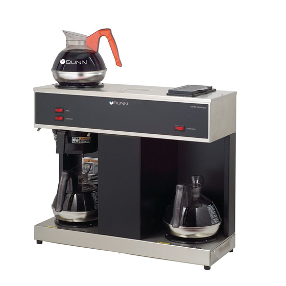
COFFEE MAKER, BUNN MODELS VPR & VPS
SUPERSEDURE NOTICE: THIS MANUAL SUPERSEDES S6161-FSE-010
REVISION 1, DATED 30 SEPTEMBER 2002, AND ALL CHANGES THERETO.
DISTRIBUTION STATEMENT A: APPROVED FOR PUBLIC RELEASE; DISTRIBUTION IS UNLIMITED.
PUBLISHED BY DIRECTION OF COMMANDER, NAVAL SEA SYSTEMS COMMAND
*0910LP9841762*
TECHNICAL MANUAL
OPERATING AND SERVICE MANUAL
FOR
REVISION 2
01 DEC 2013
Advertisement

Related Manuals for Bunn VPR


Summary of Contents for Bunn VPR
- Page 1 S6161-L6-FSE-010 REVISION 2 TECHNICAL MANUAL COFFEE MAKER, BUNN MODELS VPR & VPS OPERATING AND SERVICE MANUAL SUPERSEDURE NOTICE: THIS MANUAL SUPERSEDES S6161-FSE-010 REVISION 1, DATED 30 SEPTEMBER 2002, AND ALL CHANGES THERETO. DISTRIBUTION STATEMENT A: APPROVED FOR PUBLIC RELEASE; DISTRIBUTION IS UNLIMITED.
- Page 3 Requisition No.: N/A Equipment: Coffee Maker, Bunn Models VPR & VPS National Stock Number: 0910-LP-984-1762 Title: Coffee Maker, Bunn Models VPR & VPS; Operating and Service Manual Additional Identification: N/A Date: 12/01/2013 1. ADDITIONAL COPIES: Additional copies are available from the Naval Logistics Library (NLL).
- Page 7 This technical manual provides installation and parts list information for the Coffee Maker, Models VPR & VPS, manufactured by Bunn O Matic Corporation. This manual is intended for guidance of and use by personnel operating and maintaining the equipment described herein.
- Page 9 S6161-L6-FSE-010 SAFETY SUMMARY GENERAL SAFETY NOTICES The following general safety notices supplement the specific warnings and cautions appearing elsewhere in this manual. They are recommended precautions that must be understood and applied during operation and maintenance of the equipment covered herein. Should situations arise that are not covered in the general or specific safety precautions, the commanding officer or other authority will issue orders as deemed necessary to cover the situation.
- Page 10 S6161-L6-FSE-010 RESUSCITATION Personnel working with or near high voltage shall be familiar with approved methods of resuscitation. Should someone be injured and stop breathing, begin resuscitation immediately. A delay could cost the victim’s life. Resuscitation procedures shall be posted in all electrically hazardous areas. GENERAL PRECAUTIONS The following general precautions are to be observed at all times.
- Page 11 S6161-L6-FSE-010 n. Ensure that area is well-ventilated when using cleaning compound or solvent. Avoid prolonged breathing of fumes and compound or solvent contact with skin or eyes.
-
Page 13: Serial Numbers
PART I SERIAL NUMBERS 10053.0000G & 10784.0000G... - Page 15 PART I / SECTION I SECTION I OPERATING & SERVICE MANUAL...
- Page 17 PART I / SECTION I...
- Page 18 PART I / SECTION I TABLE OF CONTENTS PAGE Table of Contents Introduction User Notices Electrical Requirements, Initial Set-Up, and Cleaning Troubleshooting Service Schematic Wiring Diagrams (VPR & VPS) Schematic Wiring Diagrams (VPRA & VPSA) Page 1...
- Page 19 PART I / SECTION I...
- Page 21 PART I / SECTION I...
- Page 22 PART I / SECTION I...
- Page 23 PART I / SECTION I...
- Page 24 PART I / SECTION I...
-
Page 35: Illustrated Parts Catalog
PART I / SECTION II SECTION II ILLUSTRATED PARTS CATALOG... - Page 37 PART I / SECTION I...
- Page 38 S6161-L6-FSE-010 PART I / SECTION II...
- Page 40 S6161-L6-FSE-010 PART I / SECTION II...
- Page 42 S6161-L6-FSE-010 PART I / SECTION II...
- Page 44 S6161-L6-FSE-010 PART I / SECTION II...
- Page 46 S6161-L6-FSE-010 PART I / SECTION II...
- Page 48 S6161-L6-FSE-010 PART I / SECTION II...
- Page 50 S6161-L6-FSE-010 PART I / SECTION II...
- Page 52 S6161-L6-FSE-010 PART I / SECTION II...
- Page 54 S6161-L6-FSE-010 PART I / SECTION II...
- Page 56 S6161-L6-FSE-010 PART I / SECTION II...
- Page 58 S6161-L6-FSE-010 PART I / SECTION II...
- Page 60 S6161-L6-FSE-010 PART I / SECTION II...
- Page 65 PART II SERIAL NUMBERS 10053.001A, 41667.0000A, AND 40667.0000D...
- Page 67 PART II / SECTION I SECTION I INSTALLATION & OPERATING GUIDE...
- Page 70 SOLE OPTION AS SPECIFIED HEREIN, TO REPAIR, REPLACEMENT OR REFUND. In no event shall BUNN be liable for any other damage or loss, including, but not limited to, lost profits, lost sales, loss of use of equipment, claims of Buyer’s customers, cost of capital, cost of down time, cost of substitute equipment, facilities or services, or any other special, incidental or consequential damages.
- Page 71 PART II / SECTION I S6161-L6-FSE-010 TABLE OF CONTENTS PAGE Warranty Information Table of Contents User Notices Electrical Requirements and Initial Set-Up Cleaning Page 2...
- Page 76 PART II / SECTION II SECTION II SERVICE & REPAIR MANUAL...
- Page 79 SOLE OPTION AS SPECIFIED HEREIN, TO REPAIR, REPLACEMENT OR REFUND. In no event shall BUNN be liable for any other damage or loss, including, but not limited to, lost profits, lost sales, loss of use of equipment, claims of Buyer’s customers, cost of capital, cost of down time, cost of substitute equipment, facilities or services, or any other special, incidental or consequential damages.
- Page 80 Contents ......................3 Troubleshooting ....................4 Component Access ..................7 Control Thermostat ..................8 Limit Thermostat (VPR - VPS) ..............10 ON/OFF Switch (Warmers) ................11 Tank Heater ....................12 Thermal Cut-Off (VPRA - VPSA) ..............13 Warmer Elements..................14 Wiring Diagrams ...................
-
Page 81: Troubleshooting
PART II / SECTION II TROUBLESHOOTING A troubleshooting guide is provided to suggest probable causes and remedies for the most likely problems encountered. If the problem remains after exhausting the troubleshooting steps, contact the Bunn-O-Matic Technical Service Department. • Inspection, testing, and repair of electrical equipment should be performed only by qualified service person- nel. - Page 82 2. Coffee Grind for proper extraction. A six-hole stainless steel spray- 3. Sprayhead head must be used for proper extraction. The BUNN paper filter must be ® 4. Funnel Loading centered in the funnel and the bed of grounds leveled by gentle shaking.
- Page 83 PART II / SECTION II TROUBLESHOOTING (cont.) PROBLEM PROBABLE CAUSE REMEDY Dry coffee grounds remain in 1. Funnel Loading The BUNN paper filter must be ® the funnel centered in the funnel and the bed of grounds leveled by gently shaking.
- Page 86 PART II / SECTION II SERVICE (cont.) Slide the grommet to the line 4.5" above the bulb on the new capillary tube. CONTROL THERMOSTAT (cont.) Insert the capillary bulb through the hole in the tank lid and press the grommet firmly and evenly so that the groove in the grommet fits into the Removal and Replacement: tank lid.
- Page 96 PART II / SECTION III SECTION III ILLUSTRATED PARTS CATALOG...
- Page 99 SOLE OPTION AS SPECIFIED HEREIN, TO REPAIR, REPLACEMENT OR REFUND. In no event shall BUNN be liable for any other damage or loss, including, but not limited to, lost profi ts, lost sales, loss of use of equipment, claims of Buyer’s customers, cost of capital, cost of down time, cost of substitute equipment, facilities or services, or any other special, incidental or consequential damages.
-
Page 102: Trunk, Base And Panels
33211.1005 Housing W/Decal, Trunk (Includes # 2) (TC Models) 33211.1003 Housing W/Decal, Trunk (Includes # 2) (APS Models) 33767.0000 Housing W/Decal, Trunk (Includes item 11) (VPR w/Warmers) 00658.0000 Decal, Caution - Decanter/Funnel 01592.0000 Bushing, Snap - 1.0" Dia (Late Models) 01663.0000... - Page 104 S6161-L6-FSE-010 PART II / SECTION III HOOD AND TOP COVER ITEM PART NO. QTY. DESCRIPTION 38498.1000 Flip Lid Assy (Includes items 2 and 3) 37881.0000 Decal, Warning No Serviceable Parts 12981.0001 Lid/Chain Kit 37985.1003 Cover Assembly, Top (TC/APS) (Includes # 1,2,6) 33797.0000 Cover Assembly, Top (Warmer Model) (Includes # 1,2,6, 10) 01303.0000...
-
Page 106: Fill Basin
S6161-L6-FSE-010 PART II / SECTION III FILL BASIN ITEM PART NO. QTY. DESCRIPTION 01200.0000 Fitting, Tank Inlet .562˝ Opening 01212.0000 Fitting, Tank Inlet .382˝ Opening 06220.0000 Fill Basin (SST) 01201.0000 Gasket, Tank Inlet 11424.0000 Plate, Splash Guard 40667 011711... - Page 108 S6161-L6-FSE-010 PART II / SECTION III TANK AND COMPONENTS - EARLY MODELS ITEM PART NO. QTY. DESCRIPTION 05697.0006 Tank Assembly, 1320W 120V (Includes items 1 thru 17 & 20 thru 23) 01315.0000 Screw, Truss Head (SST) 8-32 x .38” 04309.0000 Terminal Block 01390.0000 Screw, Round Head (SST) 8-32 x .62”...
-
Page 110: Tab Tank And Components
S6161-L6-FSE-010 PART II / SECTION III 3 TAB TANK AND COMPONENTS ITEM PART NO. QTY. DESCRIPTION 39598.0001 Tank 05555.0001 Kit, Sprayhead Tube (Includes Grommet) 37376.0004 Grommet, Sprayhead Tube 01075.0000 Nut, Hex .438”-20 01082.0000 Sprayhead, 6-Hole 29329.1000 Thermostat, Limit 07073.1000 Grommet, Thermostat 20264.0000 Blanket Warmer, 55W 120V 39294.1002... -
Page 112: Funnels, Pitcher And Filter Basket
S6161-L6-FSE-010 PART II / SECTION III FUNNELS, PITCHER AND FILTER BASKET ITEM PART NO. QTY. DESCRIPTION 20583.0003 Funnel W/Decals, Plastic - Blk Includes items 7, 8 & 9 20583.0006 Funnel W/Decals, Plastic - Orn 20216.0000 Funnel, SST W/Black Handle (7.125" Dia.) (Includes Items 3 thru 8) 20216.0001 Funnel, SST W/Orange Handle (7.125"... -
Page 114: Warmers And Galley Kit
S6161-L6-FSE-010 PART II / SECTION III WARMERS AND GALLEY KIT ITEM PART NO. QTY. DESCRIPTION 24783.0000 Galley Kit (Includes # 2 - 6) 24730.0000 Galley Rail, SST 01303.0000 Screw, Pan Head (SST) 4-40 x .50” 02776.0000 Leg, Extension - 3.50HT 02324.0000 Nut, Acorn (SST) 8-32 02332.0002... - Page 115 S6161-L6-FSE-010 PART II / SECTION III NUMERICAL INDEX PART NO. PAGE NO. PART NO. PAGE NO. PART NO. PAGE NO. PART NO. PAGE NO. 00603.0000......7 05545.0000......11 37985.1003......7 00658.0000......5 05555.0001......13 38498.1000......7 00720.0000..... 7,11 05555.0002......11 39002.0002......
- Page 117 Ref: NAVSEAINST 4160.3 NAVSEA S0005-AA-GYD-030/TMMP NAVSEA/SPAWAR TECHNICAL MANUAL DEFICIENCY/EVALUATION REPORT (TMDER) INSTRUCTIONS: Continue on 8 ½” x 11” on page if additional space is needed. 1. Use this report to indicate deficiencies, problems and recommendations relating to publications. 2. For CLASSIFIED TMDERs see OPNAVINST 5510H for mailing requirements. 3.
- Page 118 FOLD HERE AND TAPE SECURELY PLEASE DO NOT STAPLE INCLUDE COMPLETE ADDRESS PROPER POSTAGE FOR OFFICIAL USE ONLY COMMANDER CODE 310 TMDERs NAVSURFWARCENDIV NSDSA 4363 MISSILE WAY BLDG 1389 PORT HUENEME CA 93043-4307 FOLD HERE AND TAPE SECURELY PLEASE DO NOT STAPLE...
- Page 120 S6161-L6-FSE-010...
Need help?
Do you have a question about the VPR and is the answer not in the manual?
Questions and answers