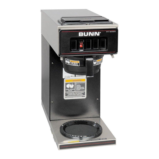
Bunn VP17 series Service & Repair Manual
Hide thumbs
Also See for VP17 series:
- Installation manual ,
- Illustrated parts catalog (26 pages) ,
- Operating & service manual (19 pages)
Summary of Contents for Bunn VP17 series
- Page 1 VP17 Series SERVICE & REPAIR MANUAL BUNN-O-MATIC CORPORATION POST OFFICE BOX 3227 SPRINGFIELD, ILLINOIS 62708-3227 PHONE: (217) 529-6601 FAX: (217) 529-6644 46721.0000A 05/12 ©2012 Bunn-O-Matic Corporation...
- Page 2 AS SPECIFIED HEREIN, TO REPAIR, REPLACEMENT OR REFUND. In no event shall BUNN be liable for any other damage or loss, including, but not limited to, lost profits, lost sales, loss of use of equipment, claims of Buyer’s customers, cost of capital, cost of down time, cost of substitute equipment, facilities or services, or any other special, incidental or consequential damages.
-
Page 3: Table Of Contents
SERVICE Contents This manual provides procedures for testing and Control Thermostat ..........4 replacing various major components used in this Limit Thermostat ..........5 brewer should service become necessary. Refer to ON/OFF Switch ............. 6 Troubleshooting for assistance in determining the Tank Heater ............ -
Page 4: Control Thermostat
SERVICE (cont.) 7. Disconnect the brewer from the power source. CONTROL THERMOSTAT If voltage is present as described, reinstall the capillary tube into the tank to the line 4.5" above the bulb, the control thermostat is operating properly. If voltage is not present as described, replace the thermostat. -
Page 5: Limit Thermostat
SERVICE (cont.) Removal and Replacement: LIMIT THERMOSTAT 1. Remove all wires from limit thermostat termi- nals. 2. Carefully slide the limit thermostat out from under the retaining clip and remove limit thermostat. 3. Carefully slide the new limit thermostat into the retaining clip. -
Page 6: On/Off Switch
SERVICE (cont.) If voltage is not present as described, refer to the Wiring ON/OFF WARMER SWITCH Diagrams and check the brewer wiring harness. 5. With the black wire removed, remove the wire from the lower terminal. 6. Check for continuity across the center and lower terminal with the switch in the "ON"... -
Page 7: Tank Heater
SERVICE (cont.) 2. Disconnect the black wire on the limit thermostat from the tank heater switch and disconnect the TANK HEATER blue wire from the limit thermostat to the control thermostat. 3. Disconnect the black wire and the white wire from the tank heater terminals. -
Page 8: Tank Heater Switch
SERVICE (cont.) If voltage is present as described, proceed to #5. TANK HEATER SWITCH (VP17B and early model If voltage is not present as described, refer to the Wiring VP17) Diagrams and check the brewer wiring harness. 5. Check for continuity between the black wire re- moved from the limit thermostat and the black insert on the terminal block, with the tank heater switch in the "ON"... - Page 9 SERVICE (cont.) TANK HEATER SWITCH (cont.) 13. Set tank assembly inside the hood on mounting brackets and secure with two #8-32 screws. 14. Reconnect the wires to the limit thermostat, tank heater and the control thermostat. Refer to Limit Thermostat, Tank Heater and Control Thermo- stat sections in this manual when reconnecting BLK to Limit Ther- wires.
-
Page 10: Warmer Elements
SERVICE (cont.) WARMER ELEMENT(S) If continuity is not present as described, replace the warmer element. Removal and Replacement: 1. Remove the three #4-40 screws securing the warmer assembly to the brewer. 2. Lift the warmer assembly from the brewer. 3. Disconnect the two wires from the warmer element terminals. -
Page 11: Wiring Diagrams
VP17-3 2 SIDE WARMERS NOT USED ON LATE MODELS WITH SIDE WARMERS BRN/BLK BRN/BLK FRONT WARMER ON/OFF SWITCH REAR WARMER ON/OFF SWITCH 120 VOLTS AC 2 WIRE + GND SINGLE PHASE 10862.0003H 09/06 ©1997 BUNN-O-MATIC CORPORATION Page 11 46721 052512... -
Page 12: Schematic Wiring Diagram
2 TOP or SIDE WARMERS BRN/BLK BRN/BLK FRONT WARMER ON/OFF SWITCH REAR WARMER ON/OFF SWITCH AUXILIARY OUTLET (NOT AVAILABLE ON VP17-3) 120 VOLTS AC 2 WIRE SINGLE PHASE 200 WATT MAXIMUM 10862.0000B 9/00 ©1995 BUNN-O-MATIC CORPORATION Page 12 46721 052512... - Page 13 BRN/BLK BRN/BLK FRONT WARMER ON/OFF SWITCH REAR WARMER ON/OFF SWITCH AUXILIARY OUTLET (NOT AVAILABLE ON VP17-3) 100 VOLTS AC 2 WIRE + GND 200 WATT MAXIMUM SINGLE PHASE (EARLY MODELS ONLY) 10862.0002G 09/06 ©1997 BUNN-O-MATIC CORPORATION Page 13 46721 052512...
- Page 14 MAIN ON/OFF SWITCH (Late Models only) 2 TOP or SIDE WARMERS NOT USED ON LATE MODELS WITH SIDE WARMERS 220-240 VOLTS AC 2 WIRE + GND SINGLE PHASE 10862.0001L 01/07 ©1995 BUNN-O-MATIC CORPORATION Page 14 46721 052512...
- Page 15 Page 15 46721 052512...
- Page 16 Page 16 46721 052512...


Need help?
Do you have a question about the VP17 series and is the answer not in the manual?
Questions and answers