Table of Contents
Advertisement
Quick Links
Advertisement
Table of Contents

Related Manuals for Lightspeed DELTA PA

Summary of Contents for Lightspeed DELTA PA
- Page 1 DELTA PA Portable Amplification System U s e r M a n u a l...
-
Page 3: Table Of Contents
Installing or Replacing Receiver Module SECTION 2: Step 1. Connecting the DELTA PA Receiver to a Power Supply Set-up & Use Step 2A. Setting up one DELTA PA Receiver Step 2B. Using More Than One DELTA PA Receiver Handheld Transmitter Step 3. Channel Selection Step 4. -
Page 4: Safety Instructions
IMPORTANT SAFETY INSTRUCTIONS Read these instructions. 11. Only use attachments/ accessories specified by the Keep these instructions. manufacturer. Heed all warnings. 12. Use only with a cart, stand, Follow all instructions. tripod, bracket or table specified by the manufacturer, Do not use the apparatus near or sold with the apparatus. -
Page 5: Overview
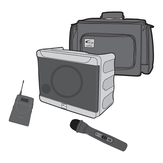
SECTION 1: OVERVIEW SYSTEM COMPONENTS AND UNPACKING The standard configuration of the DELTA PA will contain: DELTA PA Public Address System and Power Supply TX-HM016 Transmitter DELTA PA Carry Case... -
Page 6: Optional Components
OPTIONAL COMPONENTS Optional equipment which may be part of your DELTA PA system: TX-BP016 Transmitter and Charger MC-TK270S Noise- Cancelling Headset Microphone MC-831S Audio -Technica 831 Lapel Mic Individual Components RX-DPA016R 16 Channel UHF Receiver Module TX-HM016 16 Channel UHF Handheld Transmitter... - Page 7 TOP PANEL: WIRELESS RECEIVER CONTROLS RECVR 2 RECVR 2 POWER/ RECVR 1 POWER RED: LOW BATT GREEN: ON CHARGE RED: CHARGING GREEN: FULL RECVR 1 1. WIRELESS RECEIVER 1: One or 5. TRANSMITTER LOW BATTERY two wireless receiver modules are INDICATOR: This LED will light located at the top panel.
- Page 8 TOP PANEL CONTROLS AND CONNECTIONS RECVR 2 RECVR 2 POWER/ RECVR 1 POWER RED: LOW BATT GREEN: ON CHARGE RED: CHARGING GREEN: FULL RECVR 1 1. BASS: Controls the level of low 3. AUX IN/MIC IN: Controls the frequency sound output for the volume of a wired microphone system.
- Page 9 [NOTE: replacement is a 3.15A SB signal, while fully clockwise 250V slow blow fuse.] represents a line level signal. 8. DC POWER: This jack provides 5. AUX OUT: This ¼” jack provides a connection for the DELTA PA power supply.
- Page 10 INSTALLING OR REPLACING A RECEIVER MODULE NOTE: Make sure the DELTA PA is turned off. 1. Remove the two screws securing the module panel using a small phillips head screwdriver. 2. Remove the module from the enclosure by carefully inserting...
-
Page 11: Set-Up & Use
SECTION 2: SET-UP & USE 1. CONNECTING THE DELTA PA RECEIVER TO A POWER SUPPLY Note: When the DELTA PA is received, plug in the power supply and let charge overnight before using. 1. Locate the power supply. 2. Insert the DC connector into the “POWER INPUT”... - Page 12 RECVR 2 2A. SETTING UP ONE DELTA PA RECEIVER RECVR 2 1. Turn the DELTA PA ON by rotating RECVR 2 POWER/ RECVR 1 the POWER/RCVR 1 knob POWER clockwise. The GREEN LED will RECVR 2 RED: LOW BATT GREEN: ON...
- Page 13 2B. USING MORE THAN ONE DELTA PA RECEIVER If you have a second DELTA PA: A) Verify that RECVR 1 transmitter and receiver 1 are ON and set to the same clear channel. B) Make sure the transmitter for RECVR 2 is turned OFF.
- Page 14 3. CHANNEL SELECTION: HANDHELD TRANSMITTER Once a channel has been selected on the receiver, you now need to select that same channel on the handheld transmitter. If you have a belt-pack transmitter, go to page 19 for channel selection instructions. Same Channel 1.
- Page 15 Use only AA NiMH batteries when recharging. NOTE: Do not mix battery types. WARNING: Do not use NiCad batteries! They will not charge properly and may cause damage to the transmitter. Lightspeed recommends Panasonic or Energizer batteries. Duracell may not work.
- Page 16 3. Note the polarity in the battery compartment. IMPORTANT: Replace batteries with the same type, (alkaline or NiMH), that were installed in your Handheld Microphone. Lightspeed recommends Panasonic or Energizer batteries. Duracell may not work properly.
- Page 17 A full charge will be attained in 8-10 hours. Fully charged Lightspeed microphones will last over 7 hours. WARNING: Do not attempt to charge alkaline batteries. They can overheat and expand, creating a significant hazard and damaging the transmitter.
- Page 18 To remove, press the black button on the microphone connector and pull out. Microphone Options Lightspeed offers various types of microphones that can be used with this system. The BP016 Transmitter can be used with either a lapel style microphone or a headset microphone.
- Page 19 8. CHANNEL SELECTION: BELT-PACK TRANSMITTER Channel Selection: Once a channel has been selected on the receiver, you now need to select that same channel on the Belt- pack transmitter. 1. Turn the transmitter power ON by sliding the PWR button to ON. 2.
- Page 20 NOTE: If you are using a high impedance source, such as a guitar, it will be necessary to adjust the GT dial. Using a high impedance source requires a special cable. Contact Lightspeed Customer Service at 800- 732-8999 for more information.
- Page 21 AA NiMH batteries when recharging. NOTE: Do not mix battery types. WARNING: Do not use NiCad batteries! They will not charge properly and may cause damage to the transmitter. Lightspeed recommends Panasonic or Energizer batteries. Duracell may not work.
- Page 22 AA sized batteries. 3. Note the polarity in the battery compartment. IMPORTANT: Replace batteries with the same type, (alkaline or NiMH), that were installed in your Handheld Microphone. Lightspeed recommends Panasonic or Energizer batteries. Duracell may not work properly.
- Page 23 Make sure there are NiMH recharge- able batteries in the transmitter before plugging in the charger. Typical battery life is about 8 hours. Fully charged Lightspeed transmitters will last over 7 hours. A full charge will be attained in 8-10 hours.
-
Page 24: Daily Use Instructions
GREEN: FULL CHARGE RED: CHARGING GREEN: FULL NOTE: Do not stand directly in front of the DELTA PA speaker with the RECVR 1 microphone on. This will result in feedback or ‘squealing.’ It is best to RECVR 1 stand behind or to the side of the unit when setting volume level. -
Page 25: Optional Accessories
SECTION 3: OPTIONAL ACCESSORIES HANDHELD MICROPHONE TRANSMITTER 1. RED LED: Lights up briefly when power is switched on, flashes continuously when audio is muted. 2. POWER ON/OFF: Turns the audio ON and OFF. The RED LED will flash when power is turned 3. - Page 26 BELT-PACK TRANSMITTER 1. ON/OFF BUTTON compartment door. 2. RED LED: Lights up briefly when 7. GT (TRANSMITTER GAIN): power is switched ON, flashes Provides adjustment for differing continuously when audio signal is voice levels and microphone muted. sensitivities. 3. MICROPHONE JACK: 8.
-
Page 27: Troubleshooting
If the letters are different, find a If you review these instructions and still have questions, write down the serial number and model number of your system and call Lightspeed Technical Services at 800.732.8999, 5 a.m. – 5 p.m., PST. -
Page 28: Specifications
Products will be replaced or repaired at Lightspeed Technologies’ option during the warranty period. For warranty service, please contact Lightspeed Customer Service Department to obtain return authorization approval and an RA number. Our Service Department (800.732.8999, 5 a.m. – 5 p.m., PST) -
Page 29: Safety Warnings
(Example - use only shielded interface cables when connecting to computer or peripheral devices). DELTA PA & BP016 & HM016 IC ID Caution This device complies with Industry Canada licence-exempt RSS-123 standard. -
Page 30: System Specifications
SYSTEM SPECIFICATIONS OVERALL SPECIFICATIONS Nominal SPL [1W/1M] 89 dB Maximum SPL 102 dB 30 W at 2 Ω System Power [RMS] 40 W at 2 Ω Music Power [RMS] Amplifier Type Analog Class AB Frequency Response of amplifier 90 Hz - 18 kHz Full-Range 6.5”/4 Ω... - Page 31 SYSTEM SPECIFICATIONS CONT’D RECEIVER SPECIFICATIONS Carrier System Microprocessor Controlled PLL Synthesized Macro Frequency Range 620 to 679.75 MHz [3 Macro-Groups] Micro Frequency Range 25 MHz each Macro-Group Selectable Frequencies Deviation ± 40 KHz Nominal Sensitivity -100 dBm at S/N ratio of >80 dB Tone-code Frequency 32.768 KHz Image Rejection...
- Page 32 LI GHTSPEE D TE CHNOLOGIES 11509 S W HERM AN ROA D / T UA LATIN, OR 97062 TOLL FREE: 8 00. 732 .89 99 / P HONE: 503.684. 5538 / FAX : 503.684.319 7 LIGHTSPEED-TEK .COM MN0374US01-3...
Need help?
Do you have a question about the DELTA PA and is the answer not in the manual?
Questions and answers