Table of Contents
Advertisement
Quick Links
Download this manual
See also:
Service Manual
Advertisement
Table of Contents

Related Manuals for Vxl Itona TC63yy


Summary of Contents for Vxl Itona TC63yy
- Page 1 Itona TC63yy Hardware User Guide...
- Page 2 Copyright © 2004-2013 VXL Instruments Limited. All Rights Reserved Information in this document is subject to change without notice and does not represent a commitment on the part of the manufacturer. No part of this guide may be reproduced or transmitted in any form or means, electronic or mechanical, including photocopying and recording, for any purpose, without the express written permission of the manufacturer.
- Page 3 Federal Communication Commission (FCC) Statement This equipment has been tested and found to comply with the limits for a Class B digital device, pursuant to Part 15 of the FCC Rules. These limits are designed to provide reasonable protection against harmful interference in a residential installation. This equipment generates uses and can radiate radio frequency energy and, if not installed and used in accordance with the instructions, may cause harmful interference to radio communications.
-
Page 4: Regulatory Certifications
Regulatory Certifications... -
Page 5: Table Of Contents
Table of Contents Federal Communication Commission (FCC) Statement Regulatory Certifications Introduction About the User Guide Abbreviations and Acronyms Chapters in the Manual Installation Unpacking the Unit Preparing to Connect Connecting the Accessories and Power Supply Connecting to the Server Specifications Hardware Mechanical Environmental Operating... -
Page 6: Introduction
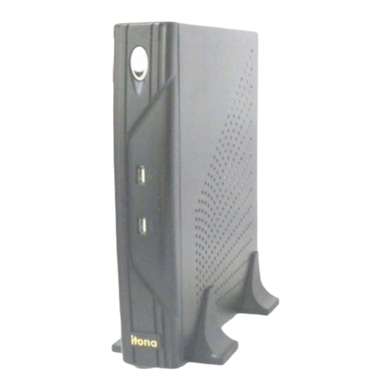
1. Power Button. 2. USB Ports. Figure 1: ItonaTC63yy Itona TC63yy deliver smart and robust solutions for Thin Client computing. They are aesthetically and ergonomically designed compact desktop. Itona series thin clients offer fanless CPU solution to enhance reliability. About the User Guide This User Guide provides step by step instructions to install Itona D series hardware. -
Page 7: Abbreviations And Acronyms
Abbreviations and Acronyms Abbreviation Expansion Alternating Current Direct Current Local Area Network Light Emitting Diode TCP/IP Transmission Control Protocol/Internet Protocol Universal Serial Bus VESA Video Electronics Standards Association Video Graphics Array Table 1: Abbreviations and Acronyms Chapters in the Manual Chapter No Chapter Name Description... - Page 8 This equipment must be earthed to prevent accidental electric shocks, connect a three pin connector to ensure adequate earthing. As a precaution, the AC socket outlet should be near the equipment and should be easily accessible. Sound Power Level is less than 60dB (A), when measured according to ISO 7779. Caution ...
-
Page 9: Installation
Installation You have to install the client before you can use it. Installation involves setting up the hardware and connecting the peripherals required for normal use. To install the Itona TC 63yy hardware, perform the following steps: 1. Unpack the unit. 2. -
Page 10: Connecting The Accessories And Power Supply
1. Audio Line Out 2. 2x Ethernet Ports. 3. LPT Port 4. PS/2 Mouse Port 5. MIC 6.4xUSB 7. COM Port 8. SVGA Port 9. PS/2 Keyboard Port 10. AC Power Out Ac Power IN Figure 2: Itona TC63yy Series Rear View Installation... - Page 11 Connectors Connector Symbol Video port USB port Audio output (LINE OUT) port Microphone input port PS/2 Keyboard port PS/2 Mouse port COM port Parallel/LPR port RJ45 Ethernet port Table 3: Connector Symbols Note: Before connecting any cables, ensure that the power cable is unplugged from the unit. To connect various accessories and power supply: 1.
-
Page 12: Connecting To The Server
Connecting to the Server The Thin Client can be physically connected to the server/network by connecting to LAN through TCP/IP. To connect client to LAN through TCP/IP: 1. Connect one end of a 10/100/1000 cable to the Ethernet LAN port of the client. 2. -
Page 13: Specifications
Specifications Hardware Processor Intel Atom N270 1.6 GHz VGA Memory Shared Video Memory 64MB min, 128MB max. Flash IDE 44 Pin 128MB ~ 2GB DDRII 533/667 Networking1 10/100Mbps Networking 2 10/100/1000Mbps Power Supply Internal Power Supply Display Resolution 16/32 Bits 1920x1200 @60Hz max Mechanical Product Dimension Height... -
Page 14: Electrical - External Power Adapter
Electrical – External Power Adapter Line Voltage 100V to 240V AC (+6, -10%) Line Frequency 50 / 60 Hz Power Inlet 1.2A, 3-pin power plug (IEC 320) Power Oulett 3-pin power socket (IEC 320 ) For devices upto 0.30A max., 100VAC~50/60Hz. -
Page 15: Troubleshooting
Troubleshooting This chapter contains solutions for problems you may encounter while using the product. Problem Solution The power-LED on front panel Ensure that the power cord is plugged into an AC outlet. does not glow when the client Check the fuse in the power-plug, if available. is switched on. -
Page 16: Appendix
Appendix Side Wall Mounting Bracket To install single side wall mounting bracket for TC63yy: Drill four holes on the wall and insert four M7x33 wall plugs.. 2. Place Single Side Wall Mounting Bracket 3. Fix the four M4x24 self taped screws. 4. - Page 17 Connectors The following section provides pin details for various connectors on the rear panel of the client. COM Port 9-pin D-type male connector, RS232C compatible, operating at 115.2K baud maximum. Signal Description Data Carrier Detect Receive Data Transmit Data Data Terminal Ready Signal Ground Data Set Ready...
- Page 18 ACKNOWLEDGE BUSY PAPER END SLCT ERROR 18-25 GROUND 10/100/1000 Ethernet LAN Port RJ-45 modular 8-pin jack. 10/100/1000 Mbps. Signal TxD+ TxD- RxD+ RxD- Video Port 15-pin D-type female connector. Signal Signal Signal Red return GND No Connection Appendix...
- Page 19 Green Green return GND No Connection Blue Blue return GND Horizontal Sync No Connection No Connection Vertical Sync No Connection No Connection Mouse/keyboard Port PS/2 Mouse / Keyboard connector. Signal Signal Mouse/Keyboa rd data Mouse/Keyboard clock Audio / Microphone Port Standard audio jacks.
- Page 20 Cables 10/100/1000 LAN Cable Cross Connection-(Without Hub) RJ45 RJ45 TXD+ 1 3 RXD+ TXD- 2 6 RXD- 1 TXD+ RXD+ 3 RXD- 6 2 TXD- Straight Connection-(With Hub) RJ45 RJ45 TXD+ 1 1 TXD+ TXD- 2 2 TXD- 3 RXD+ RXD+ 3 RXD- 6 6 RXD-...
- Page 21 9-pin to 25-pin Straight Connection Printer Cable The following table shows the pin connections of the Standard Centronics parallel cable. Some manufacturers change pin functions or polarity on their printers. For such printers, custom cables may be necessary. Refer to your printer manual for cabling information in such cases. Note: Use certified shielded cables only.
Need help?
Do you have a question about the Itona TC63yy and is the answer not in the manual?
Questions and answers