Table of Contents
Advertisement
Quick Links
Advertisement
Table of Contents

Related Manuals for Briteq LED Blaster 108


Summary of Contents for Briteq LED Blaster 108
- Page 1 U S E R M A N U A L V e r 1,0 WWW.BRITEQ-LIGHTING.COM...
-
Page 3: Product (General)
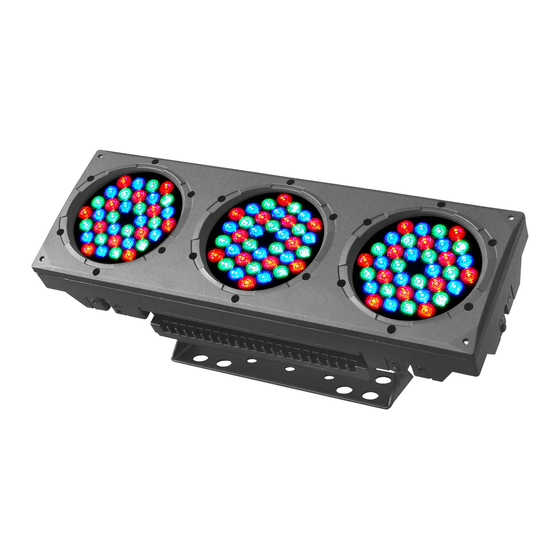
PRODUCT (GENERAL) PRODUCT INTRODUCTION This product is designed for indoor or outdoor use. Suitable applications include wash or effect lighting for architectural, stage or nightclub applications. This product can also be installed for use in signage and advertising using the dynamic functions available with DMX512 control. -
Page 4: Technical Specifications
TECHNICAL SPECIFICATIONS LED MODULE LED MODULE: Voltage 100~240V...50/60Hz Rated Power 150W IP65 protection rating 108pcs (36 x RED / 36 x GREEN / 36 x BLUE) LED/Unit Output/LED Cooling Direct air convection Dimensions 570 x 220 x 190mm Weight 13Kg 2008.8.13 1 PRODUCT(GENERAL) -
Page 5: Photometric Data
PHOTOMETRIC DATA PHOTOMETRIC DATA RGB 100% 9100 2910 1370 643 LUX 2(0.9x0.5) 4(1.4x1.0) 6(2.0x1.6) 8(2.5x2.1) 10(3.0x2.6Area(m)) Diameter(m) WHITE 8100 2570 1160 575 LUX 2(0.9x0.5) 4(1.4x1.0) 6(2.0x1.6) 8(2.5x2.1) 10(3.0x2.6Area(m)) Diameter(m) 2900 197 LUX 2(0.9x0.5) 4(1.4x1.0) 6(2.0x1.6) 8(2.5x2.1) 10(3.0x2.6Area(m)) Diameter(m) GREEN 1752 396 LUX 5565 2(0.9x0.5) -
Page 6: Safety Warning
SAFETY WARNING IMPORTANT ALWAYS READ THE USER MANUAL BEFORE OPERATION. PLEASE CONFIRM THAT THE POWER SUPPLY STATED ON THE PRODUCT IS THE SAME AS THE MAINS POWER SUPPLY IN YOUR AREA. This product must be installed by a qualified professional. Always operate the equipment as described in the user manual. -
Page 7: Installation
INSTALLATION MOUNTING HANGING The LED MODULE can be mounted in a hanging position using the support frame. It is possible to use any bolt of the correct size and s t r e n g t h t o m o u n t t h e f i x t u r e . I t i s recommended to use at least 2 mounting points per fixture. -
Page 8: Interlocking Multiple Fixtures
INTERLOCKING MULTIPLE FIXTURES The diagram above shows how multiple units can be interlocked together to create a 'panel' or 'blinder' arrangement. The 'male' and 'female' connections enable the fixtures to be interlocked together in the way shown in the diagram. Please note that when multiple units are mounted together it is not necessary to attach every single unit to the truss, wall or weight supporting system. -
Page 9: Dmx512 Addressing Without Id Addressing
SETTING UP WITH A DMX512 CONTROLLER 2.4-1 DMX512 ADDRESSING WITHOUT ID ADDRESSING (STAGE 1 MODE) Connect the DMX512 controller to the units in series. Each unit has 12 DMX channels so the DMX Addresses should increase by increments of 12 (e.g. 1,13,25,37...) The ID address has not been set so therefore when using the controller CH10 must be inactive ( CH10=0 ). - Page 10 Example: DMX Addr.1 DMX Addr.1 DMX Addr.1 DMX Addr.13 DMX Addr.13 DMX Addr.13 ID Addr.1 ID Addr.2 ID Addr.3 ID Addr.1 ID Addr.2 ID Addr.3 ... . The figure above shows a simple DMX layout which has used three units at each DMX address.
-
Page 11: Display Panel Operation
DISPLAY PANEL OPERATION BASIC The LED fixture is mounted with a LCD display and 4 control buttons. DOWN EXIT enter the currently selected menu or confirm the current function value scroll 'UP' through the menu list or increase the value of the current function scroll 'DOWN' through the menu list or decrease the value of the current function exit from the current menu or function 2008.8.13... - Page 12 MENU MENU Static color Dimmer Dimmer Green Green Blue Blue Color macros Color macros Strobe Strobe Address Address 1 DMX512 Personality STAGE 1 STAGE 2 PIXEL ARC 1 ARC 1+D Run mode Auto program Auto 1 Auto 2 Auto 3 Auto 4 Auto 5 Auto 6...
-
Page 13: Creating A Static Color
CREATING A STATIC COLOR MENU Static color Dimmer Dimmer Green Green Blue Blue Color macros Color macros Strobe Strobe Static colour Combine RED, GREEN and BLUE to create an infinite range of colors (0-255) Enter Color macros allow to choose 18 color macros Set value of dimmer (0-255) Set the value of the strobe (0-20Hz) DMX512 SETTINGS... -
Page 14: Activating An Auto Program
ACTIVATING AN AUTO PROGRAM MENU Auto program Auto 1 Auto 2 Auto 3 Auto 4 Auto 5 Auto 6 Auto 7 Auto 8 Auto Program Select the target Auto mode and press to display CHANGING THE SETTINGS MENU Settings ID address ID address 06 6 ID ON/OFF... -
Page 15: A Ctivate The Password
A CTIVATE THE PASSWORD MENU Password ON/OFF Password ON/OFF Set Password Password Enter the Password mode to set password YES/NO When password is activated, display will demand password each time the fixture is powered on. Enter the Set password menu to change password. Set new password using the &... -
Page 16: Channel Assignment
USING A DMX512 CONTROLLER BASIC ADDRESSING Connect all of the units in series using standard DMX512 signal cable or the IP65 rated cable provided. Set the DMX512 address in the 'DMX512 Address' menu. It is possible to have the same DMX address or independent addresses for each fixture. CHANNEL ASSIGNMENT Note: This product has four DMX512 channel configurations (STAGE 1 , STAGE 2 ,PIXEL,... - Page 17 STAGE 1(DMX MODE 1) CHANNEL VALUE FUNCTION No function 0-100% GREEN No function 0-100% BLUE No function 0-100% YELLOW No function 0-100% CYAN No function 0-100% PURPLE No function 0-100% WHITE No function 0-100% STROBE No function Strobe (slow to fast) MODE SELECTION No function Color-Cycle Mode 1...
- Page 18 CHANNEL VALUE FUNCTION ID ADDRESS SELECTION (also see pg. 26) Select all ID addresses ID address #1 ID address #2 ID address #3 ID address #20 ID address #21 ID address #22 ID address #23 ID address #66 MODULE SELECTION #1 ON #2 ON #3 ON #1 ON #2 ON...
- Page 19 STAGE 1(DMX MODE 2) CHANNEL VALUE FUNCTION MODULE #1 No function GREEN BLUE YELLOW PURPLE CYAN PINK-WHITE MODULE #2 No function GREEN BLUE YELLOW PURPLE CYAN PINK-WHITE MODULE #3 No function GREEN BLUE YELLOW PURPLE CYAN PINK-WHITE NO FUNCTION NO FUNCTION NO FUNCTION NO FUNCTION STROBE...
- Page 20 CHANNEL VALUE FUNCTION ID ADDRESS SELECTION (also see pg. 26) Select all ID addresses ID address #1 ID address #2 ID address #3 ID address #20 ID address #21 ID address #22 ID address #23 ID address #66 NO FUNCTION NO FUNCTION 2008.8.13 USING A DMX512 CONTROLLER...
- Page 21 STAGE 2(DMX MODE 1) CHANNEL VALUE FUNCTION DIMMER No function 0-100% No function 0-100% GREEN No function 0-100% BLUE No function 0-100% COLOR MACROS No function (100%) RED+GREEN (R85%+G15%) RED+GREEN (R60%+G40%) YELLOW (100%) RED+GREEN (R15%+G85%) RED+GREEN (R40%+G60%) GREEN (100%) GREEN+BLUE (G85%+B15%) GREEN+BLUE (G60%+B40%)
- Page 22 CHANNEL VALUE FUNCTION MODE SELECTION No function Color-Cycle Mode 1 Color-Cycle Mode 2 Color-Cycle Mode 3 Color-Cycle Mode 4 (speed can be adjusted using Channel 11) Color-Cycle Mode 5 Color-Cycle Mode 6 Color-Cycle Mode 7 Color-Cycle Mode 8 DMX MODE 2 ID ADDRESS SELECTION (also see pg.
- Page 23 STAGE 2(DMX MODE 2) CHANNEL VALUE FUNCTION MODULE #1 No function GREEN BLUE YELLOW PURPLE CYAN PINK-WHITE MODULE #2 No function GREEN BLUE YELLOW PURPLE CYAN PINK-WHITE MODULE #3 No function GREEN BLUE YELLOW PURPLE CYAN PINK-WHITE NO FUNCTION NO FUNCTION STROBE No function Strobe (slow to fast)
- Page 24 CHANNEL VALUE FUNCTION ID ADDRESS SELECTION (also see pg. 26) Select all ID addresses ID address #1 ID address #2 ID address #3 ID address #20 ID address #21 ID address #22 ID address #23 ID address #66 NO FUNCTION NO FUNCTION PIXEL CHANNEL...
-
Page 25: Operation
BASIC INSTRUCTIONS FOR DMX512 OPERATION STAGE 1 DMX MODE 1 RED, GREEN & BLUE COLOR SELECTION CH1, CH2 & CH3 control the intensity ratio of each of the RED, GREEN & BLUE LEDs. When the slider is at the highest position (255) the intensity of the color is the maximum. - Page 26 STAGE 1 DMX MODE 2 MODULE #1, MODULE #2 & MODULE #3 SELECTION CH1, CH2 & CH3 allow quick-and-simple control of the three LED MODULEs Control of the LED MODULEs can be used in conjunction with all other channels in DMX MODE 2 STROBE CH8 is the strobe channel and controls the strobe effects of CH1, CH2 &...
- Page 27 STAGE 2 DMX MODE 2 MODULE #1, MODULE #2 & MODULE #3 SELECTION CH1, CH2 & CH3 allow quick-and-simple control of the three LED MODULEs Control of the LED MODULEs can be used in conjunction with all other channels in DMX MODE 2 STROBE CH6 is the strobe channel and controls the strobe effects of CH1, CH2 &...
- Page 28 PROGRAMMING WITH A DMX512 CONTROLLER: EXAMPLES(STAGE 1) EXAMPLE 1 Before any operation is performed on the DMX512 controller, confirm that all DMX channels are set to zero. NOTE When programming a step / scene that involves operating CH10 to select an ID address, this channels operation should be performed first to select RED for MODULE #1 (ID Add.
- Page 29 EXAMPLE 2 Before any operation is performed on the DMX512 controller, confirm that all DMX channels are set to zero. to select RED for all MODULES (ID Add. 1) to select NO GREEN for all MODULES (ID Add.1) ID Addr.1 ID Addr.2 to select NO BLUE for all MODULES Step 1...
- Page 30 to set OFF for MODULE #1 (ID Add. 1) to select OFF for MODULE 2 (ID Add.1) ID Addr.1 ID Addr.2 Step 7 to select OFF for MODULE 3 (ID Add.1) to select DMX mode 1 to select ID Add. 1 CH10 to select RED for all MODULES (ID Add.
- Page 31 EXAMPLE 3 Before any operation is performed on the DMX512 controller, confirm that all DMX channels are set to zero. to select RED for all MODULES (ID Add. 1) to select NO GREEN for all MODULES (ID Add. 1) Step 1 to select NO BLUE for all MODULES (ID Add.1) to select DMX mode 1 to select ID Add.
-
Page 32: Troubleshooting
APPENDIX TROUBLE SHOOTING LED MODULE SITUATION CAUSE ACTION PART ORDER NUMBER 1) Power connection error 1) Check all power connections No display 2) Main PCB fuse overheated 2) Replace fuse 16-03-0020-03 3) Main PCB damaged 3) Replace main PCB 26-2A-LED301MD4-00 LED MODULE on, Display board damaged Replace display board...
Need help?
Do you have a question about the LED Blaster 108 and is the answer not in the manual?
Questions and answers