Table of Contents
Advertisement
Quick Links
Advertisement
Table of Contents

Related Manuals for Briteq BT-54L3


Summary of Contents for Briteq BT-54L3
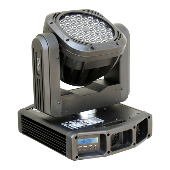
- Page 1 LED MOVING WASH USER MANUAL Ver 1,0...
-
Page 2: Table Of Contents
ABLE OF CONTENTS PART 1 PRODUCT (GENERAL)..............1. 1.1--PRODUCT INTRODUCTION................1. 1.2--PRODUCT FEATURES................1. 1.3--TECHNICAL SPECIFICATIONS..............2. 1.4--PHOTOMETRIC DATA.................3. 1.5--SAFETY WARNING..................4. PART 2 INSTALLATION ................5. 2.1-- MOUNTING ....................5. FUSE REPLACEMENT 2.2-- ................6. 2.3-- SETTING UP (STAND ALONE) ..............6. 2.4-- SETTING UP (MASTER/SLAVE) ..............7. 2.5-- SETTING UP (DMX512 CONTROLLER) ............ -
Page 3: Part 1 Product (General)
PRODUCT (GENERAL) PRODUCT INTRODUCTION This product is designed for indoor use only. Suitable applications include wash or effect lighting for architectural, stage or nightclub applications. Direct input of DMX512 signal allows the fixtures to be controlled from any DMX512 controller. The fixture is fully programmable with one custom program available and is supplied with two automatic programs (all accessible from DMX512 controller). -
Page 4: Technical Specifications
TECHNICAL SPECIFICATIONS Voltage 100~240V...50/60Hz Rated Power 280W LED/Unit 54pcs (14 X 2W RED / 14 X 3W GREEN / 14 X 3W BLUE/12 X 3W WHITE) Cooling Forced air convection Dimensions 390 x 320 x 385mm Weight 16Kg 1 PRODUCT(GENERAL) 2008.7.31... -
Page 5: Photometric Data
PHOTOMETRIC DATA WHITE 1550 277 LUX 6300 10Distance(m) 5140 1373 238 LUX 10Distance(m) GREEN 2320 1055 398 LUX 9360 10Distance(m) BLUE 1710 73 LUX 10Distance(m) 16050 3920 1765 1010 670 LUX 10Distance(m) RGB+WHITE 20200 5400 2430 1400 950 LUX 10Distance(m) 1 PRODUCT(GENERAL) 2008.7.31... -
Page 6: Safety Warning
SAFETY WARNING IMPORTANT ALWAYS READ THE USER MANUAL BEFORE OPERATION. PLEASE CONFIRM THAT THE POWER SUPPLY STATED ON THE PRODUCT IS THE SAME AS THE MAINS POWER SUPPLY IN YOUR AREA. This product must be installed by a qualified professional. Always operate the equipment as described in the user manual. -
Page 7: Part 2 Installation
INSTALLATION MOUNTING The LED fixture can be operated in any position at any angle. When mounted on a flat surface, the surface must be strong enough to support 10 times the weight of the fixture and stable so that the will be no damage caused to the fixture or surrounding people or objects because of movements of the fixture on the surface. -
Page 8: Fuse Replacement
FUSE REPLACEMENT Remove the safety cap by a screwdriver. etch the old fuse from safety cap. nstall a new fuse. nstall the safety cap. Safety Cap Fuse SETTING UP (STAND ALONE) The LED fixture can be used as a stand alone unit. The stand alone functions AUTO 1, AUTO 2, CUSTOM can be activated without the need to connect to any controller or connecting to any other equipment. -
Page 9: Setting Up (Master/Slave)
SETTING UP (MASTER/SLAVE) When units are connected in series using DMX512 signal cable connect the units as shown in the diagram below Connect the (male) 3 pin connector side of the DMX cable to the output (female) 3 pin connector of the first (MASTER) fixture. Connect the end of the cable coming from the MASTER fixture which will have a (female) 3 pin connector to the input connector of the next fixture consisting of a (male) 3 pin connector. -
Page 10: Part 3 Display Panel Operation
DISPLAY PANEL OPERATION BASIC The LED fixture is mounted with a LCD display and 4 control buttons. MENU ENTER DOWN MENU Scroll through the main menu or exit from the current sub-menu ENTER Enter the currently selected menu or confirm the current function value DOWN Scroll 'DOWN' through the menu list or decrease the value of the current function Scroll 'UP' through the menu list or increase the value of the current function MENU... - Page 11 (000~255) 3 Range 3.1P/start (000~255) 3.2P/Finish (000~255) 3.3T/start (000~255) 3.4T/Finish 3.5 Use 4.1 BlackDelay 4 Special 4.2Reset System Normal 4.3 Dimmer Special 4.4 RGB 4.5 Fan System (001~255) 5.1STEP 5 EDIT 5.2pan (000~255) 5.3tilt (000~255) 5.4speed (000~255) 5.5 red (000~255) 5.6 green (000~255) 5.7 blue...
-
Page 12: Intro
(000~255) 7.7 W7:6500K 7.7 RED (000~255) 7.7 GREEN (000~255) 7.7 BLUE (000~255) 7.8 W8:7200K 7.8 RED (000~255) 7.8 GREEN (000~255) 7.8 BLUE (000~255) 7.9 W9:8000K 7.9 RED (000~255) 7.9 GREEN (000~255) 7.9 BLUE (000~255) 7.10 W10:8500K 7.10 RED (000~255) 7.10 GREEN (000~255) 7.10 BLUE 7.11 W11:10000K... -
Page 13: Invert
1.1 Address Enter 1.1 Address to set the DMX Address, which is from (001-512) 1.2 Reset In order to rest custom modest to default, select 1.2 Reset 1.3 Fans Enter 1.3 Fans to select the working mode of fan: High is for fast;... -
Page 14: 3.5 Range
3.5 RANGE MENU (000~255) 3 Range 3.1P/start (000~255) 3.2P/Finish (000~255) 3.3T/start (000~255) 3.4T/Finish 3.5 Use 3.1P/start Set pan start value 000~255 3.2P/Finish Set pan finish value 000~255 3.3T/start Set Tilt start value 000~255 3.4T/Finish Set Tilt finish value 000~255 3.5 Use Enter 3.5 Use and select... -
Page 15: Edit
EDIT MENU (001~255) 5 EDIT 5.1STEP 5.2pan (000~255) 5.3tilt (000~255) 5.4speed (000~255) 5.5 red (000~255) 5.6 green (000~255) 5.7 blue (000~255) 5.8 white (000~255) (000~255) 5.9 strobe 5.10 dim-speed (000~255) 5.11 time (000~255) 5.12 Use 5 EDIT Enter the 5 EDIT mode to edit the custom programs by adjusting the value of 5.1STEP , 5.2pan , 5.3tilt , 5.4speed , 5.5 red , 5.6 green , 5.7 blue , 5.8 white , 5.9 strobe , 5.10 dim-speed , 5.11 time... -
Page 16: Calib
CALIB MENU 7.1 W1:3200K (000~255) 7 Calib 7.1 RED (000~255) 7.1 GREEN (000~255) 7.1 BLUE (000~255) 7.2 W2:3400K 7.2 RED (000~255) 7.2 GREEN (000~255) 7.2 BLUE (000~255) 7.3 W3:4200K 7.3 RED (000~255) 7.3 GREEN (000~255) 7.3 BLUE (000~255) 7.4 W4:4900K 7.4 RED (000~255) 7.4 GREEN... -
Page 17: Codechange
3.10 CODECHANGE MENU 8.1 User-key 8 CodeChange **** 8.2password **** 8 CodeChange elect 8.1 User-key to set the password elect 8.2 Password to set the password. Note: 8.2 Password will not appear only when 6.2 password is activated. 3.11 DEFAULT MENU 9 Default 9.1 Default... -
Page 18: Part 4 Using A Dmx512 Controller
USING A DMX512 CONTROLLER BASIC ADDRESSING Connect all of the units in series using standard DMX512 signal cable . Set the DMX512 address in the DMX menu. It is possible to have the same DMX address or independent addresses for each fixture. CHANNEL ASSIGNMENT Note: This product have two DMX512 channel configuration: ADVANCED... - Page 19 CHANNEL VALUE FUNCTION COLOR/WHITE MACRO NO FUNCTION RED UP/GREEN 0%/BLUE 100% RED 100%/GREEN UP/BLUE DOWN RED DOWN/GREEN 100%/BLUE 0% RED 0%/GREEN DOWN/BLUE UP RED UP/GREEN 0%/BLUE DOWN RED DOWN /GREEN UP/BLUE 0% RED UP / GREEN 100% / BLUE 0% RED DOWN / GREEN DOWN/ BLUE UP NO FUNCTION NO FUNCTION...
- Page 20 BASIC CHANNEL VALUE FUNCTION Clockwise rotate 0~ TILT Anti-clockwise rotate 0~270 GREEN BLUE WHITE COLOR/WHITE MACRO NO FUNCTION RED UP/GREEN 0%/BLUE 100% RED 100%/GREEN UP/BLUE DOWN RED DOWN/GREEN 100%/BLUE 0% RED 0%/GREEN DOWN/BLUE UP RED UP/GREEN 0%/BLUE DOWN RED DOWN /GREEN UP/BLUE 0% RED UP / GREEN 100% / BLUE 0% RED DOWN / GREEN DOWN/ BLUE UP NO FUNCTION...
- Page 21 FUNCTION EXPLANATION CH1 adjusts the PAN from 0 to 540 PAN FINE CH2 adjusts the PAN from 0 to 3 TILT CH3 adjusts the TILT from 0 to 270 TILT FINE CH4 adjusts the TILT from 0 to 3 PAN/TILT SPEED CH5 adjusts the speed of the PAN and TILT faders RED, GREEN , BLUE &...
-
Page 22: Part 5 Appendix
APPENDIX TROUBLE SHOOTING SITUATION CAUSE ACTION PART ORDER NUMBER Power connection error Check all power connections No display Power switch damaged Replace power switch 16-03-0042-00 Display board damaged Replace display board 26-2A-2107CDI4-00 LED MODULE on, but no control Display board damaged Replace display board 26-2A-2107CDI4-00 from display... -
Page 23: Maintenance
MAINTENANCE ITEM ITEM Plastic front cover Base upper cover 1 Lens upper cover DMX board Lens Side coverB Handle Lens base cover Power socket LED board Fuse LED board supporting base Heat-transfer plate Switch Base bottom cover Plastic head cover Power supply Back cover for head Base upper cover 2...
Need help?
Do you have a question about the BT-54L3 and is the answer not in the manual?
Questions and answers