Table of Contents
Advertisement
Quick Links
M
odel
Compact Digital
MultiMeter
Instruction Manual
1. Introduction
The Triplett Model 1401 multimeter is a 6000 count, handheld digital
multimeter with auto-ranging capability, AC RMS measurement, automatic
power off and a backlit LCD display. Using a Large Scale Integration (LSI)
integrated circuit, the multimeter is designed for stability and accuracy. The
resilient outer molded cover provides additional protection from the occa-
sional fall, and the threaded probe tips and screw on insulated clips provide
for secure, hands-off measurements. The meter can measure AC and DC
voltage, AC and DC current, resistance, capacitance, frequency/duty cycle,
temperature, and forward diode voltage drop. It can also perform an audible
continuity test, non-contact AC voltage detection, and test both 1.5V and 9V
batteries.
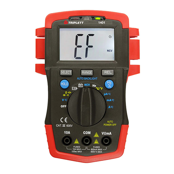
2. Product Features
1) Test lead holder.
2) CDS sensor for automatic backlight brightness control.
3) NCV Detection area (top of DMM case).
4) NCV Detection voltage detected indicator (red LED).
5) NCV Detection mode activated indicator (green LED)
6) LCD display with
(Low Battery), NCV, DH (Hold) and measurement
unit annunciators.
7) SELECT button: With the rotary switch on the "
this button to select resistance, diode, continuity or capacitance tests.
With the switch on either voltage or current selections, this switches
between DC and AC settings. If the temperature °C/°F is selected, it
switches between Centigrade or Fahrenheit. If the SELECT button is
held down while the meter is turned on, the "Auto Power Off " function will
be disabled.
8) RANGE button: Press and release the "RANGE" button to enter manual
range mode. Additional presses cause the unit to change the
measurement range of the measurement function selected. Press and
holding the button for more than 2 seconds causes the meter to toggle
back to auto-ranging mode.
9) DISPLAY HOLD Button: Press the "HOLD" key to lock the present value
on the display. The "DH" sign will appear on the display while the hold
function is active. Press it again to exit and resume normal display
updating.
10) REL button: Press this button for the meter to enter relative
measurement mode. "REL" is displayed on the LCD and the present
reading becomes the reference value. In this mode, the displayed value
is the difference between any subsequent measurement and the
reference value: Relative measurement = measurement
value-Reference value.
11) Hz/% button: On "ACV/ACA" or "Hz" range, pressing the "Hz/%" key,
switches between Frequency or Duty Cycle measurements.
12) Rotary Switch: Use this switch to select test functions and ranges.
13) COM: COM and Temperature "-" Input Jack.
14) 10A: 10A Input Jack, fused at 10A., 500V
15) VΩmA: V/mA/BATT/
800mA, 500V
16) Meter case
17) Protective molded cover
1401
" range, press
and Temperature "+" Input Jack, fused at
3. Safety Information
3-1 The meter is designed according to IEC-1010 concerning electronic
measuring instruments with an over-voltage category level of 600V
(CAT III) and pollution level 2. DO NOT USE THIS METER FOR CAT
IV APPLICATIONS.
3-2 Follow all safety and operating instructions to ensure that the meter is
used safely and is kept in good operating condition.
3-3 Safety symbols:
Important safety information, refer to the operating manual.
Dangerous voltage may be present.
Double insulation (protection Class II)
4. Cautions and Warnings
4-1 To maintain product safety, use the provided test leads. Damaged test
leads should be replaced with the same model or test leads with the
same electrical specifications.
4-2 Do not use with the battery cover removed.
4-3 Always set the rotary switch to the correct position for measurement.
4-4 Do not exceed the input limits.
4-5 Do not change the rotary switch setting when the leads are connected to
an energized circuit.
4-6 Use caution when measuring voltages higher than 60V DC or 30V AC.
4-7 Replace fuse with fuse of the same rating.
4-8 To conserve battery life, always turn the meter off when measurements
are completed.
5. General Characteristics
5-1 Max Voltage between input terminal and Earth Ground: CAT III 600V
5-2 Over-range Indication: display "1" or "-1" for the most significant digit
5-3 Low Battery Indication:
5-4 Maximum LCD Display: 5999 (3 ½ digits)
5-5 Auto and manual range selection
5-6 Auto Power Off: The meter will switch to standby mode when it has
been on for approximately 20 minutes.
5-7 Fuse protection: Fast acting 800mA/500V and 10A/500V fuses.
5-8 Power supply: 2 x 1.5V AA batties (R6, or LR6)
5-9 Operating Temperature: 0°C to 40°C (relative humidity <85%)
5-10 Storage Temperature: -10°C to 50°C (relative humidity <85%)
5-11 Dimension: 150x106x36mm
5-12 Weight: approx. 250g (including battery)
6. Measurement Specifications
Accuracy is specified from 18°C to 28°C (64°F to 82°F) with relative
humidity below 70%.
Range
Resolution
600.0mV
0.1mV
6.000V
1mV
60.00V
10mV
600.0V
100V
600V
1V
Impedance: 10MΩ, >100MΩ on 600mV range
Overload protection: 600V DC or AC
AC Voltage (True RMS)
Range
Resolution
6.000V
1mV
60.00V
10mV
600.0V
100mV
600V
1V
Impedance: 10MΩ - Overload protection: 600V DC or AC rms
Frequency Range: 40 to 400Hz
Range
Resolution
600µA
0.1µA
6000µA
1µA
60mA
10µA
600mA
100µA
6A
1mA
10A
10mA
-- Overload protection: 800mA/500V Fast Fuse
10A/500V Fast Fuse, 10A up to 10 seconds
is displayed
DC Voltage
Accuracy
±(0.5% of rdg + 2 digits)
±(0.8% of rdg + 2 digits)
Accuracy
±(1.0% of rdg + 3 digits)
±(1.5% of rdg + 3 digits)
DC Current
Accuracy
±(1.2% of rdg + 2 digits)
±(2.0% of rdg + 3 digits)
Advertisement
Table of Contents

Related Manuals for Triplett 1401


Summary of Contents for Triplett 1401
-
Page 1: Instruction Manual
1. Introduction 4-2 Do not use with the battery cover removed. The Triplett Model 1401 multimeter is a 6000 count, handheld digital 4-3 Always set the rotary switch to the correct position for measurement. multimeter with auto-ranging capability, AC RMS measurement, automatic 4-4 Do not exceed the input limits. -
Page 2: Operating Instructions
AC Current Diode test Range Resolution Accuracy Range Description Resolution 600µA 0.1µA Forward voltage drop of diode 6000µA 1µA Overload protection: 500V AC / DC ±(1.5% of rdg + 3 digits) 60mA 10µA Test Current: Approximately 1.5mA Open Circuit Voltage: Approximately 3.2V 600mA 100µA Continuity test... - Page 3 7-5 Measuring AC Current 7-10-3 Connect the test leads to the two points of the circuit under test. Press the SELECT button once the continuity symbol appears 7-5-1 Connect the black test lead to COM jack and red lead to VΩmA jack on the top of the LCD and the “Ω”...
- Page 4 Some states (USA ONLY) do not allow the exclusion or limitation of inci- dental or consequential damages, so the above limitation or exclusion may not apply to you No representative of Triplett / Byte Brothers or any other person is authorized to extend the liability of Triplett in connection with the sale of its products beyond the terms hereof.
Need help?
Do you have a question about the 1401 and is the answer not in the manual?
Questions and answers