Table of Contents
Advertisement
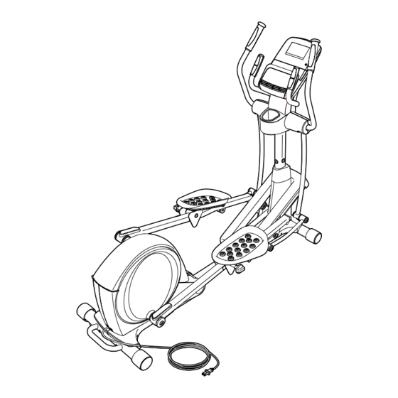
USER'S MANUAL
Model No. SFEL16011.1
Serial No.
Write the serial number in the space
above for reference.
Serial Number
Decal
QUESTIONS?
If you have questions, or if parts
are damaged or missing, DO NOT
CONTACT THE STORE; please
contact Customer Care.
IMPORTANT: Please register this
product (see the limited warranty
on the back cover of this manual)
before contacting Customer Care.
CALL TOLL-FREE:
1-866-362-4490
Mon.–Fri., 6 a.m.–6 p.m. MT
Sat. 8 a.m.–4 p.m. MT
CAUTION
Read all precautions and instruc-
tions in this manual before using
this equipment. Keep this manual
for future reference.
Advertisement
Table of Contents

Related Manuals for Freemotion 510 Rear Drive


Summary of Contents for Freemotion 510 Rear Drive
- Page 1 USER’S MANUAL Model No. SFEL16011.1 Serial No. Write the serial number in the space above for reference. Serial Number Decal QUESTIONS? If you have questions, or if parts are damaged or missing, DO NOT CONTACT THE STORE; please contact Customer Care. IMPORTANT: Please register this product (see the limited warranty on the back cover of this manual)
-
Page 2: Table Of Contents
Apply the decal in the location shown. Note: The decal(s) may not be shown at actual size. 218557 259345 166909 218556 258865 FREEMOTION is a registered trademark of ICON IP, Inc. -
Page 3: Important Precautions
IMPORTANT PRECAUTIONS WARNING: To reduce the risk of serious injury, read all important precautions and instructions in this manual and all warnings on your elliptical before using your elliptical. ICON assumes no responsibility for personal injury or property damage sustained by or through the use of this product. -
Page 4: Before You Begin
Thank you for selecting the revolutionary reading this manual, please see the front cover of this FREEMOTION 510 REAR DRIVE elliptical. The 510 manual. To help us assist you, note the product model ® REAR DRIVE elliptical provides an impressive selec- number and serial number before contacting us. -
Page 5: Part Identification Chart
PART IDENTIFICATION CHART Use the drawings below to identify the small parts needed for assembly. The number in parentheses below each drawing is the key number of the part, from the PART LIST near the end of this manual. The number following the key number is the quantity needed for assembly. -
Page 6: Assembly
ASSEMBLY • To hire an authorized service technician to • Place all parts in a cleared area and remove the assemble the elliptical, call 1-800-445-2480. packing materials. Do not dispose of the packing materials until you complete all assembly steps. • To watch an assembly video, go to www.freemotionfitness.com/assembly or use • To identify small parts, see page 5. - Page 7 2. Orient the Front Stabilizer (3) so that the indi- cated hole is facing the pin on the Main Frame (1). While a second person lifts the front of the Main Frame (1), attach the Front Stabilizer (3) with two M10 x 95mm Screws (100). Hole 3.
- Page 8 4. Tip: Avoid pinching the Main Wire (60). Insert the Upright (5) into the Main Frame (1). Attach the Upright (5) with four M8 x 16mm Screws (102) and four M8 Split Washers (103); Avoid pinching the do not tighten the Screws yet. You will Main Wire (60) tighten the Screws at the end of step 11.
- Page 9 6. Identify the Right Pedal (14), the Right Pedal Insert (117), and the Right Pedal Arm (12), which are marked with “Right” stickers, and orient them as shown. Attach the Right Pedal (14) and the Right Pedal Insert (117) to the Right Pedal Plate (80) with four M6 x 12mm Screws (146).
- Page 10 8. See drawing 8a. Locate the Pedal Arm Roller (32) on the Right Pedal Arm (12). Set the Pedal Arm Roller (32) on the right side of the Ramp (130). See drawing 8b. Pull upward on the Latch (50) on the Right Pedal Arm (12). Press the Right Pedal Arm (12) onto the right Pedal Arm Sleeve (46).
- Page 11 9. Orient the Ramp Cover (131) around the Upright (5) as shown. Press the Mounts (not shown) on the underside of the Ramp Cover (131) into the Ramp (130). 10. Apply grease to a Link Arm Axle (114). Insert the Link Arm Axle (114) into the Right Upper Body Leg (6) and the Right Link Arm (43) from the side shown.
- Page 12 11. Identify the Right Upper Body Arm (8), which is marked with a “Right” sticker, and orient it as shown. Have a second person hold the Right Upper Body Arm (8) near the Right Upper Body Leg (6). Attach the Right Upper Body Arm (8) to the Right Upper Body Leg (6) with three M8 x 16mm Screws (102) and three M8 Split Washers (103).
- Page 13 13. Note: If you purchase the optional chest heart rate monitor (see page 24), see step 17 on page 14 to install the receiver included with the heart rate monitor. Orient the Rear Upright Cover (25) as shown. Attach the Rear Upright Cover (25) to the Upright (5) with four M4 x 19mm Screws (125).
- Page 14 15. Orient the Front Upright Cover (24) as shown. Attach the Front Upright Cover (24) around the Upright (5) by pressing the tabs on the Front Upright Cover into the Rear Upright Cover (25). 16. Make sure that all parts are properly tightened before you use the elliptical. Note: After assembly is com- pleted, some extra parts may be left over.
-
Page 15: How To Use The Elliptical
HOW TO USE THE ELLIPTICAL HOW TO PLUG IN THE POWER CORD A temporary adapter may 2-pole Receptacle This product must be grounded. If it should malfunc- be used to tion or break down, grounding provides a path of least connect the Adapter resistance for electric current to reduce the risk of elec-... - Page 16 HOW TO MOVE THE ELLIPTICAL Next, raise the pedal arms until the magnets on the pedal arms touch the handlebars; the magnets will hold the pedal arms in place. Then, hold the handle and lift To move the elliptical, first fold it as described on page the frame until it locks in a vertical position.
- Page 17 HOW TO LEVEL THE ELLIPTICAL HOW TO EXERCISE ON THE ELLIPTICAL If the elliptical To mount the elliptical, hold the upper body arms or the rocks slightly on handlebars and step onto the pedal that is in the lowest your floor during position.
- Page 18 CONSOLE DIAGRAM FEATURES OF THE CONSOLE The console also features revolutionary iFit Live technology that enables the console to communicate The advanced console offers an array of features with your wireless network through an optional iFit Live designed to make your workouts more effective and module.
- Page 19 HOW TO TURN ON THE POWER HOW TO USE THE MANUAL MODE IMPORTANT: If the elliptical has been exposed to 1. Begin pedaling or press any button on the cold temperatures, allow it to warm to room tem- console to turn on the console. perature before turning on the power.
- Page 20 4. Follow your progress with the display. Stride—This display mode will show the total num- ber of strides you have pedaled. The display can show the following workout Time—When the manual mode is selected, this information: display mode will show the elapsed time. When a workout is selected, this display mode will show the time remaining in the workout.
- Page 21 When a wireless iFit When your pulse is detected, a heart symbol will Live module is con- flash in the display each time your heart beats, nected, the wireless one or two dashes will appear, and then your heart rate will be shown. For the most accurate heart symbol at the top rate reading, hold the contacts for at least 15 of the display will...
- Page 22 HOW TO USE AN ONBOARD WORKOUT At the end of each segment of the workout, a series of tones will sound and the next segment of 1. Begin pedaling or press any button on the the profile will begin to flash. If a different resis- console to turn on the console.
- Page 23 HOW TO USE AN IFIT LIVE WORKOUT 5. Select an iFit Live workout. You must have an iFit Live module to use an iFit Live To select an iFit Live workout, press one of the workout. iFit Live buttons. Note: Before some workouts will download, you must go to www.iFit.com and add To purchase an iFit Live module at any time, go to them to your schedule.
- Page 24 7. Follow your progress with the display. HOW TO USE THE SOUND SYSTEM See step 4 on page 20. To play music or audio books through the console sound system while you exercise, plug the included The My Trail tab will show a map of the trail you are audio cable into the jack on the console and into a jack walking or running or it will show a track and the on your MP3 player or CD player;...
- Page 25 HOW TO CHANGE CONSOLE SETTINGS If no module is connected, the display will show the words NO IFIT MODULE. If no module is con- The console features a user mode that allows you to nected, go to step 10. view usage information, select a unit of measurement, 6.
-
Page 26: Fcc Information
FCC INFORMATION This equipment has been tested and found to comply with the limits for a Class B digital device, pursuant to part 15 of the FCC Rules. These limits are designed to provide reasonable protection against harmful interference in a residential installation. This equipment generates, uses, and can radiate radio frequency energy and, if not installed and used in accordance with the instructions, may cause harmful interference to radio communications. -
Page 27: Maintenance And Troubleshooting
MAINTENANCE AND TROUBLESHOOTING Inspect and tighten all parts of the elliptical regularly. Next, look into the access opening and locate the Reed Replace any worn parts immediately. Switch (69). Rotate the Large Pulley (74) until a Pulley Magnet (75) is aligned with the Reed Switch. To clean the elliptical, use a damp cloth and a small amount of mild soap. - Page 28 HOW TO ADJUST THE DRIVE BELT Loosen the Pivot Screw (97). Tighten the Belt Adjustment Screw (85) until the Drive Belt (38) is tight. If you can feel the pedals slip while you are pedaling, When the Drive Belt is tight, tighten the Pivot Screw. even when the resistance is adjusted to the highest level, the drive belt may need to be adjusted.
-
Page 29: Exercise Guidelines
EXERCISE GUIDELINES Burning Fat—To burn fat effectively, you must exer- WARNING: cise at a low intensity level for a sustained period of Before beginning this time. During the first few minutes of exercise, your or any exercise program, consult your physi- body uses carbohydrate calories for energy. - Page 30 SUGGESTED STRETCHES The correct form for several basic stretches is shown at the right. Move slowly as you stretch —never bounce. 1. Toe Touch Stretch Stand with your knees bent slightly and slowly bend forward from your hips. Allow your back and shoulders to relax as you reach down toward your toes as far as possible.
-
Page 31: Part List
PART LIST Model No. SFEL16011.1 R0112B Key No. Qty. Description Key No. Qty. Description Main Frame Large Latch Spring Folding Frame Latch Insert Front Stabilizer Long Latch Spring Rear Stabilizer Arm/Leg Bushing Upright M4 x 16mm Flat Head Screw Right Upper Body Leg Small Axle Cover Left Upper Body Leg Upright Bushing... - Page 32 Key No. Qty. Description Key No. Qty. Description Small Pedal Arm Snap Ring Ramp Cover M8 x 16mm Screw Ramp Bushing M8 Split Washer Ramp Axle Lift Arm Snap Ring Lift Motor Pulse Wire Lift Motor Wire M4 x 16mm Screw Ramp Roller M10 x 20mm Screw Long Motor Axle...
-
Page 33: Exploded Drawing
EXPLODED DRAWING A Model No. SFEL16011.1 R0112B... - Page 34 EXPLODED DRAWING B Model No. SFEL16011.1 R0112B...
- Page 35 EXPLODED DRAWING C Model No. SFEL16011.1 R0112B...
-
Page 36: Ordering Replacement Parts
ORDERING REPLACEMENT PARTS To order replacement parts, please see the front cover of this manual. To help us assist you, be prepared to provide the following information when contacting us: • the model number and serial number of the product (see the front cover of this manual) • the name of the product (see the front cover of this manual) • t he key number and description of the replacement part(s) (see the PART LIST and the EXPLODED DRAWING near the end of this manual) LIMITED WARRANTY IMPORTANT: You must register this product within 30 days of the purchase date to avoid added fees for service needed under warranty.
Need help?
Do you have a question about the 510 Rear Drive and is the answer not in the manual?
Questions and answers